Numerous attempts have been made in the past to develop reliable sources of orthodontic anchorage. Recently, skeletal anchorage systems such as dental restorative implants, miniscrew or microscrew implants, and miniplates have been effectively used to obtain anchorage. However, because of their bulky size, the waiting period for osseointegration, and their high cost, dental implants have not been widely used. The extensive surgical procedure and high cost overshadow the use of plate-type anchorage, despite a high success rate. In the past decade, miniscrew or microscrew implants have gained wider acceptance because they are both easy and convenient to use. The application of skeletal anchorage has lead to a paradigm shift in orthodontic treatment from single-tooth movement to group-teeth movement.
This chapter addresses the development of microimplants, the surgical procedure involved in their placement, and the management of associated complications.
DEVELOPMENT OF MICROIMPLANTS
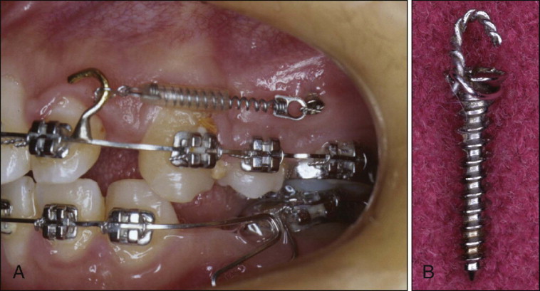
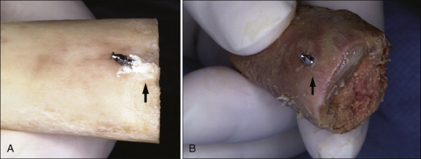
During the initial stages of development of microimplants, the author used a surgical microscrew for orthodontic anchorage, specifically the screws from Leibinger (now Stryker Osteosynthesis, a division of Stryker, Freiburg, Germany) and Osteomed (Addison, Texas) ( Fig. 23-1 ). These screws were 1.2 mm in diameter and 5 to 10 mm in length. The success rate of these surgical screws varied from 80% to 90 %, depending on the site of placement. One of the chief drawbacks of these surgical screws was a lack of any “superstructure” on the head for attaching elastics. To circumvent this problem, ligature wire was tied on the neck (under head of screw) and then bent up to make a hook. This hook caused persistent inflammation around microscrew implants.
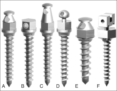
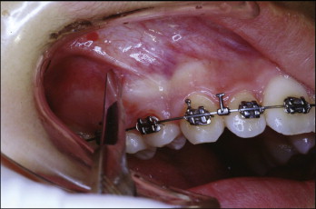
Current microimplants have a hook, button, or bracket on the head for attaching elastic materials, which minimizes inflammation. The tapered shape of trunk over head pushes the elastic material away from the soft tissue and prevents soft tissue impingement, especially around the canine eminence ( Fig. 23-2 ). To simplify the placement of implants, self-drilling microimplants have also been developed.
Size of Microimplants
Microimplants ranging from 1.2 to 1.6 mm in diameter are small enough to be placed at most anatomical locations in the mouth, including the palate, chin, retromolar area, and interradicular spaces between teeth roots. After placement, at least 6 mm of the total length of the microimplant should be embedded into the bone in the maxilla and 4 mm in the mandible. The author typically prefers to use microimplants 7 to 8 mm long in the maxillary buccal alveolar bone and 5 to 6 mm long in the mandibular buccal side. In the maxillary palatal alveolar bone, 10- to 12-mm-long microimplants need to be placed to compensate for the thick palatal soft tissue and to keep 6 mm of microimplants embedded in the bone. The most common diameter of the microimplants is 1.3 mm in the maxilla and 1.4 mm in the mandible and 1.5 or 1.6 mm in the midpalatal area where there are no teeth.
SURGICAL PROCEDURES FOR IMPLANT PLACEMENT
Anesthesia
Local anesthesia
Local anesthesia includes one-quarter ampoule for injection or application of anesthetic patch or topical anesthesia. Mild surface anesthesia of the oral mucosa maintains the sensitivity of nerve fiber in the periodontal ligament so that the patient is alert enough to know whether the pilot drill has impinged on the periodontal ligament. However, it is not always true that the pilot drill has impinged on the periodontal ligament, especially in the lower posterior teeth area. Occasionally there is pain despite no microimplant-root contact.
Topical anesthesia
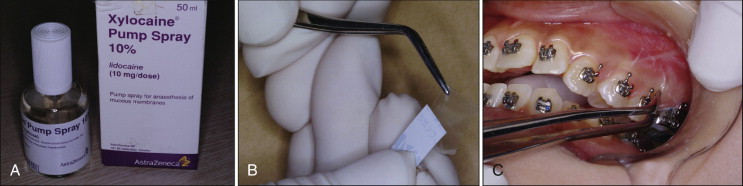
Topical anesthesia can also be used for this procedure. After drying the overlying soft tissue, topical anesthetic solution or patch can be applied ( Fig. 23-3 ). Ten minutes of waiting time is required to obtain proper anesthesia.
Infiltration anesthesia
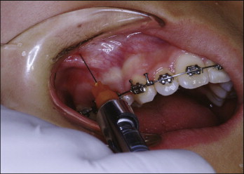
A one-third or one-quarter ampoule of anesthetic solution can be injected into mucosa ( Fig. 23-4 ). Again, by depositing comparatively small amounts of anesthetic solution, clinicians can keep the nerve fibers in the periodontal ligament sensitive. If the microimplants touch the roots, the patient might show pain. At that moment the drill needs to be redirected in a different direction. Occasionally the patient might have pain even though the microimplant does not touch the root, especially in the lower jaw. Assessment of the position of microimplants relative to the roots is essential. The best was to assess this is by taking periapical radiographs.
Incision
Placing microimplants through the oral mucosa requires a 3-mm-long stab incision ( Fig. 23-5 ). This incision can be omitted with placement in attached gingiva. The incision prevents the soft tissue from rolling up around the drill bit. Because of the small incision size, no sutures are required.
Drilling Method
There are two different methods to place microimplants: self-tapping and self-drilling. The self-tapping method requires a hole be predrilled before placing the microimplant. For placing microimplants in the mandibular posterior teeth area and maxillary palatal area (for all age groups) and in the maxillary buccal alveolar bone (for adult patients), the self-tapping method is a better option than the self-drilling method. The self-drilling method can be used to place microimplants into the buccal alveolar bone in the maxillary jaw of young patients and the maxillary and mandibular anterior teeth area in all age groups.
Self-tapping method
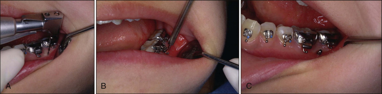
After administering local anesthesia, a pilot drill is used to make a hole in the cortical bone, and the microimplant is introduced through this hole and screwed in with a hand driver ( Fig. 23-6 ). When placing the microimplant into attached gingiva, the incision can be omitted, but when placing it in oral mucosa, a small, vertical incision is needed (see Fig. 23-4 ). Entrapping soft tissue in the hole when placing the microimplant without an incision is always a possibility and may compromise stability of the microimplant. An incision may also produce more postoperative pain and swelling.
The diameter of the pilot drill should be slightly smaller than the inner (or core) diameter of the microimplant because it provides good purchase of bone. During drilling, clinicians should abundantly irrigate with coolants to reduce heat generation. The drill speed preferred is about 600 rpm. To minimize heat generation, clinicians need to move the drill in and out from the pilot hole when drilling into dense cortical bone. The heat generated is proportionate to the pressure applied; therefore clinicians should not apply too much pressure while drilling. The drill hole should be made all the way through the cortical bone. Careful attention should be paid to keeping the axis of the drill stable so as not to enlarge the opening inadvertently.
Self-drilling method
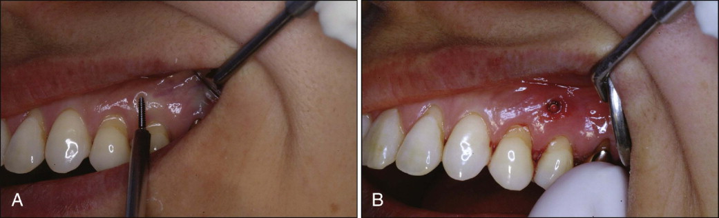
Self-drilling is a simpler method for placing the microimplant than self-tapping. The microimplant is placed in the bone through the attached gingiva without drilling ( Fig. 23-7 ). The microimplant is introduced at an angle of 90 degrees to the bone surface and screwed in with the hand driver. Placement at a certain angle requires a small indentation to be made to prevent slippage of the microimplant. The angular placement of microimplants with the self-drilling method can damage the cortical bone where it is dense and thick. If the microimplant is to be placed at an angle into dense cortical bone, the self-tapping method is always a better option.
After placement, it is important for the operator to check the three-dimensional relationship of the microimplant to the roots. Root contact can be noticeable or felt during the placement procedure because there is another strong resistance when the implant meets the root. The microimplants should be checked for firmness immediately after placement. If any mobility is detected, the implant needs to be removed and replaced by a larger-diameter implant to obtain tighter purchase.
Placement Angle
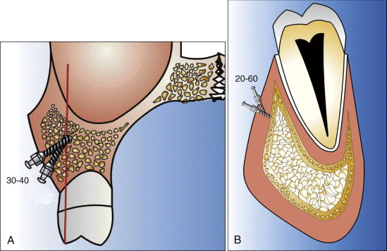
Relative to the long axis of the teeth, microimplants can be placed at an angle of 30 to 40 degrees for the upper jaw ( Fig. 23-8, A ) and 20 to 60 degrees for the lower jaw ( Fig. 23-8, B ). This angular placement reduces the possibility of root contact by positioning the apex of the microimplants toward the apical portion of the roots, where there is relatively more space. The advantages of angulating the microimplant during insertion are increased surface area of cortical bone contact with the microimplant and less chance of root contact or possible root damage (if any damage at all) if the implant hits root. Angulation also provides the operator with the option of placing longer microimplants, which may further enhance their stability. Perpendicular placement can also be done, but only after careful examination of the space between roots.
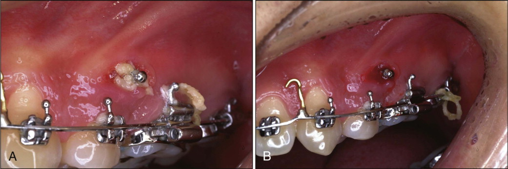
The angular placement into dense cortical bone with the self-drilling method may produce more bone fracture of the cortical bone than perpendicular placement ( Fig. 23-9 ). Again, it is better to place microimplants with the self-tapping method in dense cortical bone.
Head Exposure
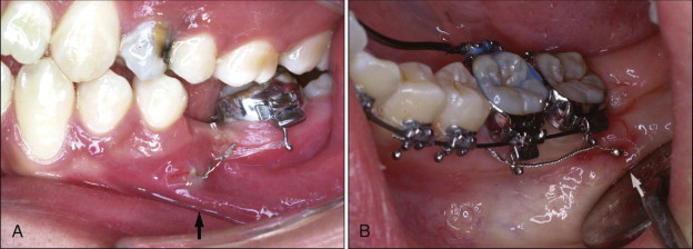
The heads of the microimplants can be exposed when placing them into attached gingiva, and the elastics or nickel-titanium (Ni-Ti) coil springs can be attached directly to the heads ( Fig. 23-10 ). The head of the microimplants, when placed deep in the vestibule or retromolar area, may get embedded by the overgrowth of the surrounding soft tissue. The no-head (NH) type of microimplant is most suitable for this situation. To apply force, ligature wire extension tied around the neck of the microimplant can be used ( Fig. 23-11 ). The Absoanchor microimplants (Dentos, Daegu, South Korea) have a small hole at the neck that can provide an attachment for engaging ligature wires.
Postoperative Management
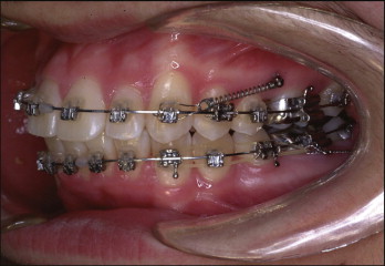
Most patients experience no noticeable discomfort or infection after the placement and removal of microimplants. Antibiotics and antiinflammatory agents need to be prescribed to minimize postoperative discomfort. Patients need to be instructed to practice good oral hygiene by spraying water with a Water Pik ( Fig. 23-12 ). Intentional or accidental application of heavy force on the microimplants during mastication should be avoided.
Timing of Loading (Application of Force)
Miyawaki et al. found no significant difference between loading at 1 to 2 months or at 3 months after placement. Melsen and Costa found no significant difference between immediate loading and delayed loading in histological sections. The author prefers to load the microimplants immediately after placement and keep the force minimal (<70 g) until 2 months after placement. After 2 months the force can be increased up to 150 to 200 g. In young, growing patients the maximum force that can be used is 200 g for retraction of all the anterior teeth or the entire arch. In adults the force for retraction of anterior teeth need not exceed 200 g. For retraction of the entire arch, force can be increased to a maximum of 400 g.
Removal of Microimplants
Stay updated, free dental videos. Join our Telegram channel
VIDEdental - Online dental courses


