Traumatic Dental Injuries
Introduction
The World Health Organisation (WHO) created a classification system for the varying types of traumatic dental injuries (TDIs) in 1992 (WHO, 1992). Two years later, this classification was modified by Andreasen and Andreasen (1994) in order to define and categorise trauma entities not presented in the original WHO classification (Tables 9-1 to 9-4).
Reports on the prevalence of TDI vary considerably due to the lack of homogeneity between studies examining this epidemiological measure. A national survey carried out in the USA, with a cohort of 154 million people between the ages of 6 and 50, revealed that almost one in three 6 to 20-year-olds and one in four 20 to 50-year-olds had suffered TDI (Kaste et al, 1996).
The accurate diagnosis of TDI is reliant on the acquisition of a thorough history, coupled with a systematic examination of the patient. This examination includes special clinical diagnostic tests and an appropriate radiographic assessment of the injured area(s) of the dentition, supporting tissues and, when indicated, adjacent soft tissues. The radiographic assessment is, and can only be, an adjunct to, and a component part of, the diagnostic process.
TDIs are often associated with the development of post-injury complications, such as pulp canal obliteration (Andreasen et al, 1987), pulp necrosis (Andreasen and Pedersen, 1985), the development of apical periodontitis (AP), root resorption (Andreasen and Pedersen, 1985), and marginal periodontal breakdown (Andreasen and Pedersen, 1985; Oikarinen et al, 1987). Any of these undesirable sequelae may occur in isolation or in combination with one or more of the others, and may result in tooth loss. As such, it is important that traumatically injured teeth are followed up clinically and radiographically in a systematic manner and according to the International Association of Dental Traumatology (IADT) guidelines, to ensure the earliest possible detection and management of these complications (IADT, 2012a). In many cases, radiographic signs of pulpal and/or periapical pathosis may be the first indication of the development of these types of complications.
Radiographic assessment of TDI
Background
Contemporary guidelines for the radiographic assessment and follow-up of traumatically injured permanent teeth advise that two periapical radiographs and an anterior occlusal radiograph be taken to assess the injured tooth (Flores et al, 2007a, b; IADT, 2012a, b). Further radiographs are specifically indicated to identify debris or tooth segments that have become embedded in soft tissues. The periapical radiographs should be taken with a beam aiming device, with the central X-ray beam centred on the tooth in question. The X-ray beam in the second periapical (parallax) radiograph should be laterally orientated to the tooth being imaged (Flores et al, 2007a, b; IADT, 2012a). However, due to the limitations of conventional radiography, the true nature of certain TDIs are extremely difficult to visualise using conventional radiographic examinations, and this is reflected in the number of radiographs recommended by the guidelines to assess the affected teeth.
Injuries occurring in the plane of the radiographic exposure (e.g. palatal luxation injuries, and fractures and comminution injuries to the labial cortical plate) and those obscured by overlying and adjacent anatomy (e.g. horizontal root fractures in which the X-ray beam is not orientated along the fracture line) may be very difficult to diagnose using conventional radiography (Andreasen, 1970; Bender and Freedland, 1983; Andreasen and Andreasen, 1985; Andreasen and Andreasen, 1988; Andreasen, 2007).
Table 9-1 Classification of injuries to the hard dental tissues and the pulp (Andreasen and Andreasen, 1994).
|
Type of injury |
Description |
|
Enamel infraction |
An incomplete fracture (crack) of the enamel without loss of tooth substance |
|
Enamel fracture |
A fracture with loss of tooth substance confined to enamel |
|
Enamel–dentine fracture (uncomplicated crown fracture) |
A fracture with loss of tooth substance confined to enamel and dentine, but not involving the pulp |
|
Complicated crown fracture |
A fracture involving enamel and dentine, exposing the pulp |
|
Uncomplicated crown–root fracture |
A fracture involving enamel, dentine and cementum, but not exposing the pulp |
|
Complicated crown–root fracture |
A fracture involving enamel, dentine and cementum, and exposing the pulp |
|
Root fracture |
A fracture involving dentine, cementum and the pulp. Root fractures can be further classified according to displacement of the coronal fragment |
Though not yet considered routine in the assessment of TDI, cone beam computed tomography (CBCT) has been shown to improve the visualisation and nature of dentoalveolar injuries (IADT, 2012a), and is indicated in situations where conventional radiographs yield limited information (Patel and Saunders, 2013; European Society of Endodontology CBCT position statement, 2014).
CBCT is indicated in current IADT guidelines as a tool that improves the monitoring of healing and assessment of complications following TDI (IADT, 2012a). Systematic conventional radiographic follow-up of traumatically injured teeth is advised and may be necessary for up to 5 years, depending on the nature of the injury (IADT, 2012a, b).
Radiographic assessment of specific TDI
a. Injuries to the hard tissues and dental pulp
Conventional radiography
Crown fracture. The extent and nature of crown fractures (enamel infraction, uncomplicated crown fracture, and complicated crown fracture; see Table 9-1) are generally diagnosed from the history provided and the clinical examination carried out. Radiographic assessment of crown fractures is nonetheless necessary in order to rule out more serious concomitant TDI not necessarily evident clinically. Furthermore, radiographs taken at the time of the injury provide information about the size of the pulp and the stage of root development of the affected tooth/teeth (Fig 9-1). These radiographs are a baseline record with which subsequent follow-up radiographs can be compared in order to assess the pulpal and periapical status of the tooth and the development of complications over time.
In the case of complicated crown fractures that have been treated using vital pulp therapy techniques, the baseline radiographs can also be used to evaluate the development of a hard tissue barrier over the pulpal exposure with time. Uncomplicated and complicated crown fractures should be assessed according to the IADT guidelines (IADT, 2012a).
Enamel infractions should be assessed with a single periapical radiograph only, unless signs or symptoms indicative of other problems are present. In the event of a crown fracture (of any type) occurring in isolation, the radiographic appearance of the affected tooth (apart from the loss of coronal tooth tissue) should appear normal. The tooth will have normal periapical architecture and the root form should be appropriate for the stage of development of the tooth.
Crown–root fracture. Crown–root fractures (Table 9-1) are most often clinically diagnosed based on the history provided, the symptoms the patient is experiencing, and visualisation of the fracture. Crown–root fractures in anterior teeth commonly have an oblique orientation and may be minimally displaced (Figs 9-2 and 9-3), as the fractured portion is retained in position by the fibres of the periodontal ligament (PDL). As such, they can be missed clinically, especially when occurring in posterior teeth, where the fracture orientation will be similar to that in anterior teeth but may involve the occlusal surface instead of extending onto the labial aspect of the tooth crown.
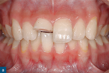
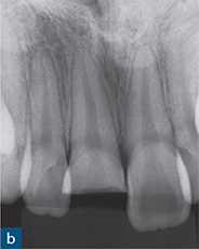
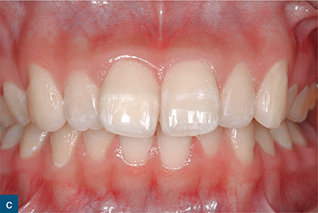
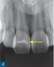
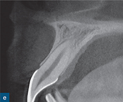
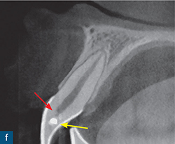
Fig 9-1 Crown fracture. (a) Clinical examination revealed a complicated crown fracture of the maxillary right central incisor (tooth 11). (b) A periapical radiograph showed that the periapical tissues appear normal. (c) Clinical view 1 year after treatment of the injury, which involved a coronal pulpotomy, a direct pulp capping procedure with CaOH and rebonding of the fractured coronal portion of the crown. (d) The 1-year review radiograph is unremarkable. The pulpal dressing is evident radiographically (yellow arrow), but there is no radiographic evidence of dentine bridge formation. (e) Sagittal CBCT view of tooth 21, which was uninjured, 1 year after the injury. The dental hard tissues and supporting periodontal tissues appear healthy. (f) Sagittal CBCT view of tooth 11, 1 year after the injury. The dental hard tissues and the periodontal tissues appear healthy. Of significance is the evidence of the formation of a hard tissue barrier (red arrow) just apical to the pulp dressing (yellow arrow).
Crown–root fractures should be assessed according to the IADT guidelines (IADT, 2012a). However, the apical extent of crown–root fractures with the common oblique orientation is very often difficult to visualise using conventional radiographic examinations, regardless of the number of parallax exposures. This is because the oblique fracture will tend to run almost perpendicular to the X-ray beam in each of the examinations, and the fractured subgingival fragment is generally well adapted to the root of the tooth. The limitations of conventional radiographic examination (see Chapter 1) means it tends not to add to the information obtained from the clinical examination (Andreasen et al, 2007b).
Crown–root fractures with a buccolingual orientation will be more readily evident on conventional radiographs, as the X-ray beam will pass through the fracture line. Crown–root fractures with a mesiodistal orientation will be more difficult to detect with conventional radiographic views, as the fracture orientation will be perpendicular to the plane of the X-ray source. The periapical anatomy of the injured tooth will appear normal on conventional radiographs immediately after the injury, as long as there is not a concomitant luxation injury.
Horizontal root fracture. The diagnosis of horizontal root fractures (HRFs) is reliant on the radiographic demonstration of the injury (Andreasen et al, 2007a). However, HRFs are generally only visible on conventional intraoral radiographs when the central X-ray beam is orientated either directly through the fracture line, or within a maximum range of 15- to 20-degrees of the orientation of the fracture line (Bender and Freedland, 1983; Andreasen and Andreasen, 1988). When the X-ray beam passes directly through the fracture line, it will be represented radiographically as a single transverse radiolucency across the root. As the X-ray beam deviates from the plane of the fracture line (within the 15 to 20 degree range), the fracture will take on a more ellipsoid appearance on the radiograph (Figs 9-4 and 9-5). With greater deviations of the X-ray beam from the fracture plane, the fracture line becomes undetectable (Andreasen and Hjørting-Hansen, 1967). These are the findings in the presence of a single transverse fracture line. Multiple root fractures will have an irregular appearance radiographically (Andreasen and Hjørting-Hansen, 1967).
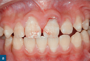
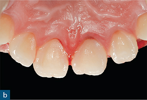
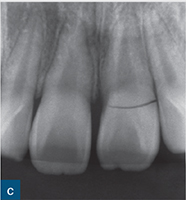
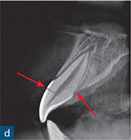
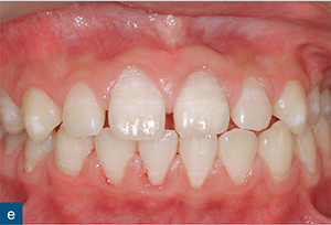
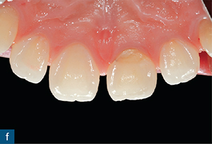
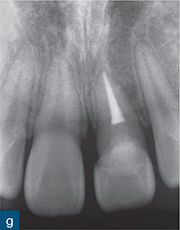
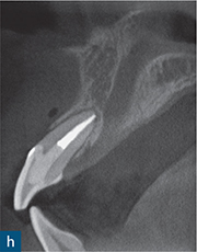
Fig 9-2 Crown–root fracture. (a and b) Labial and palatal images of the traumatically injured teeth of a 12-year-old boy, 1 hour after the injury. (c) A periapical radiograph revealed a well-defined fracture in the cervical region of the crown of the maxillary left central incisor tooth (21). (d) Sagittal CBCT view of tooth 21 reveals the course of an oblique crown–root fracture through the coronal pulp and on to the palatal surface of the root of the tooth at a subcrestal level (red arrows). As part of the treatment, the retained root was extracted, rotated 180 degrees and replanted, such that the fracture line was situated supragingivally on the labial and palatal surfaces of the tooth. The crown of the tooth was rebonded with composite 3 weeks after the surgery. (e and f) Clinical appearance at the 3-year review. (g and h) The periapical radiograph and sagittal CBCT image of tooth 21, 3 years after the injury, are unremarkable.
The course of HRFs can vary considerably, but is generally obliquely (more common in apical or mid-root fractures) or horizontally (more common in cervical third fractures) orientated. As such, periapical radiographs with a 90-degree horizontal angulation relative to the tooth under examination will be more useful at detecting horizontally orientated fractures, while occlusal views will be more useful at detecting oblique fractures. Multiple radiographic exposures are therefore necessary to assess teeth for HRFs (May et al, 2013; IADT, 2012a). However, even in situations where multiple exposures are utilised, HRFs may not always be detected in the immediate aftermath of the injury, especially if the fractured portions are still closely juxtaposed. Subsequent radiographs may then reveal a fracture. This may be due to separation of the fractured segments following subsequent haemorrhage, or granulation tissue build-up at the site of the fracture, or in the adjacent alveolar bone (Andreasen and Andreasen, 1988).
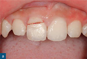
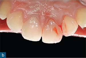
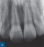
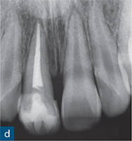
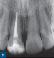
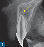
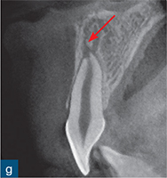
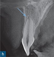
Fig 9-3 Crown–root fracture and subluxation injury. (a and b) The maxillary right central incisor tooth (11) has suffered a crown–root fracture, and the maxillary left central incisor tooth (21) has suffered a subluxation injury. The fracture associated with tooth 11 is clinically evident on the labial surface of the tooth in the cervical third of the crown, but is not evident palatally. The fracture line is located subgingivally on the palatal aspect of the tooth. (c) The periapical radiograph reveals an evident fracture line running through the middle portion of the crown of tooth 11 in a mesiodistal direction. (d) Tooth 11 was endodontically treated. (e) A 2-year review radiograph reveals signs of root canal sclerosis in the vital tooth 21. Sagittal CBCT view of tooth 21 (f) at the initial assessment reveals widening of the PDL space (not clearly evident on the radiograph) (yellow arrow). (g) At 3 months after the injury, there is evidence of transient apical breakdown on the sagittal CBCT view (red arrow). This is not evident on the periapical radiograph. (h) At 3 years after the injury, regeneration of the periapical tissues (blue arrow) is evident on the sagittal CBCT view.
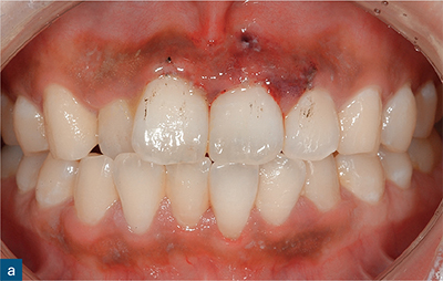
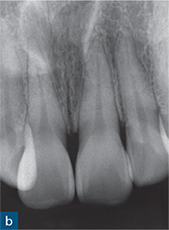
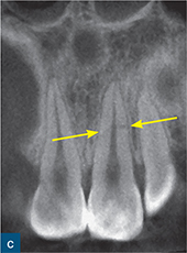
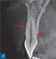
Fig 9-4 Horizontal root fracture. (a) Maxillary and mandibular anterior teeth of a 26-year-old female, 2 hours after tooth 21 was traumatically injured. (b) Periapical radiograph of the maxillary central and left lateral incisor teeth at the time of the initial assessment is unremarkable. (c) Coronal CBCT view of tooth 21 and the adjacent central and lateral incisor teeth at the assessment appointment. Tooth 21 has suffered a horizontal root fracture (HRF) at the mid-root level (yellow arrows). The adjacent teeth are uninjured and the periodontal and periapical tissues of all teeth appear healthy. (d) Sagittal CBCT view of tooth 21 at the assessment appointment reveals more information about the nature of the fracture; the HRF runs obliquely from the labial surface to the palatal surface of the root of tooth 21 in an apicocoronal direction (red arrows). Labially, the fracture line is at the mid-root level, while palatally the fracture line communicates with the PDL at a level just apical to the crestal bone.
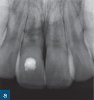
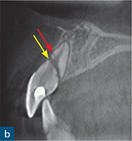
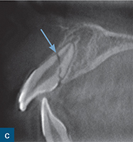
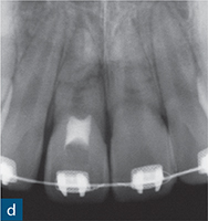
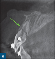
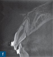
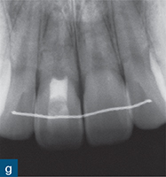
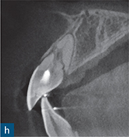
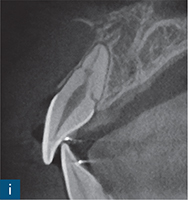
Fig 9-5 Horizontal root fracture. (a) Periapical radiograph of the maxillary central incisor teeth of a 13-year-old boy reveals HRFs associated with both central incisor teeth following a TDI 3 months earlier. It is unclear whether there are multiple fractures associated with the teeth, or whether the radiographic projection is producing an ellipsoid appearance of the fracture lines on the radiograph in one or both teeth. Endodontic treatment of the coronal portion of the root canal of the maxillary right central incisor tooth (11) was initiated 1 month earlier by the patient’s clinician following the development of a gingival abscess. (b) Sagittal CBCT of tooth 11 reveals a primary fracture running obliquely, in an apicocoronal direction, from the mid-root level of the labial root surface to the palatal surface of the root at the level of the crestal bone. The coronal fragment is significantly displaced in a coronal direction. A smaller fracture (red arrow) is evident on the labial aspect of the root, immediately apical to, and communicating with, the primary fracture. The labial alveolar bone overlying the fracture has resorbed. (c) Sagittal CBCT view of the maxillary left central incisor tooth (21) taken at the initial appointment. The root has suffered a single fracture (blue arrow). There is only minor separation of the fractured root segments. (d to f) At the 3-year review: (d) the periapical radiograph of the maxillary incisor teeth does not reveal the exact nature and degree of healing, while (e) the sagittal CBCT view of tooth 11 reveals that the labial cortical plate has regenerated and remodelled (green arrow). The apical root canal has sclerosed and there is deposition of mineralised tissue in the root canal coronal to the fracture line. The fracture line has further reduced and repaired with hard tissue deposition. The fracture has most likely repaired with connective tissue. (f) Sagittal CBCT view of tooth 21, 13 months after the injury. The fracture shows signs of repair, with interposition of some dental hard tissue in the fracture line on the palatal aspect of the root. (g) Periapical radiograph of the maxillary incisor teeth, 3 years after the injury. There appears to be continued healing of the fracture, but the exact nature and degree of healing is difficult to assess from the periapical radiograph. (h) Sagittal CBCT view of tooth 11 reveals that the labial cortical plate has healed further so that the integrity of the plate is intact. The apical root canal has sclerosed further and there is more deposition of mineralised tissue in the root canal coronal to the fracture line. The fracture line has further reduced and repaired with hard tissue deposition. (i) Sagittal CBCT view of tooth 21 reveals that the fracture has repaired completely with hard tissue, labially. There is continued repair of the palatal fracture with hard tissue. The fracture line at its junction with the PDL space, palatally, has not healed completely with hard tissue.
CBCT
Crown fracture. In cases of crown fracture, a CBCT examination might be prescribed to assess the affected tooth, or teeth, for more serious concomitant injuries. In the event that the injury is an isolated crown fracture, the CBCT data will provide a more diagnostically accurate and reliable assessment of the health of the periodontal tissues and the root of the affected tooth than that which can be provided by conventional intraoral radiography (Patel et al, 2009a; Durack et al, 2011) (Fig 9-1). In uncomplicated crown fractures, the thickness of the dentine wall at the base of the fracture and overlying the coronal pulp can be measured and compared with future scans to obtain a reliable qualitative and quantitative assessment of the degree of tertiary dentine formation following the injury. This provides some adjunctive information about the health of the pulp. In the same manner, in complicated crown fractures, review CBCT scans can be compared to the assessment scan taken at the time of the injury to objectively assess the presence and thickness (using measuring tools) of any dentine bridge formation over the exposed pulp. Conventional intraoral radiography can only offer a subjective assessment of dentinal bridge and tertiary dentine formation following crown fractures (Fig 9-1).
Table 9-2 Classification of injuries to the periodontal tissues (Andreasen and Andreasen, 1994).
|
Type of injury |
Description |
|
Concussion |
An injury to the tooth-supporting structures without abnormal loosening or displacement, but with marked reaction to percussion |
|
Subluxation |
An injury to the tooth-supporting structures with abnormal loosening, but without clinically or radiographically demonstrable displacement of the tooth |
|
Extrusive luxation |
Partial displacement of the tooth out of its socket |
|
Lateral luxation |
Displacement of the tooth in a direction other than axially. This is accompanied by comminution or fracture of the alveolar socket |
|
Intrusive luxation |
Displacement of the tooth into the alveolar bone. This injury is accompanied by comminution or fracture of the alveolar socket |
|
Avulsion |
Complete displacement of the tooth out of its socket |
< div class='tao-gold-member'>
Stay updated, free dental videos. Join our Telegram channel
VIDEdental - Online dental courses


