The aim of this article is to introduce a new concept of bracket positioning with special consideration to root axes. Cone-beam computed tomography imaging and computer-aided manufacturing were used to produce stereolithographic trays for indirect-direct bonding.
Highlights
- •
Cone-beam computed tomography imaging and 3D printing are applied in a new indirect-direct bonding technique.
- •
Bracket bases remain clean, free of resin or cast material, until they are bonded.
- •
Three-dimensional imaging allows careful control of root axes.
Since the evolution of the straight-wire appliance, attention has been directed to precise bracket placement as the key factor for ideal tooth positioning. Accurate bracket positioning enables the clinician to achieve the best treatment outcome in the shortest time and to minimize the need for further archwire bending and bracket repositioning. Various utilities have been developed for precise bracket placement along with techniques for indirect bonding.
The frequency of innovations in the design of bracket placement gauges to facilitate accurate bracket positioning is unprecedented. Although these gauges can minimize bracket positioning errors, they cannot negate them. Problems encountered during bracket positioning include inaccessibility, anatomic variations, and morphologic diversity of the clinical crowns, even for the same tooth. Above and beyond is the traditional use of the long axis of the clinical crown as a guide for bracket placement, as dictated by the straight-wire technique, which was reported to be different from the actual long axis of the tooth when the root was considered. The ability to align teeth considering both the crown and the root improves the treatment outcome and decreases the chances for posttreatment relapse.
Others have attempted to discover the best method for bracket placement. Unfortunately, none has succeeded in reporting a reproducible and reliable technique. Indirect bonding techniques were introduced to prevent the difficulties of inaccessibility and lengthy appointments while obtaining standard results, yet the human factor in bracket placement cannot be overlooked. Many factors might affect the clinician’s precision in bracket positioning. These include years of experience, sharpness of sight, and manual dexterity. The evolution of imaging techniques has opened new horizons for both diagnosis and treatment. Recent imaging techniques have allowed complete visualization of the tissues in 3 dimensions. Cone-beam computed tomography (CBCT) has proven to have great diagnostic value, with the ability to produce accurate images of the patient’s soft and hard tissues. Furthermore, computer-aided manufacturing of dental stents derived from cone-beam images has a satisfactory degree of accuracy, allowing the implementation of CBCT technology not only as a diagnostic tool but also as a treatment aid.
Material and methods
Three-dimensional (3D) images for separate brackets in a bracket kit (Roth 0.022 in; American Orthodontics, Sheboygan, Wis) were obtained from CBCT scanning. The images were first obtained in DICOM format and then converted to stereolithography format using Mimics software (Materialise, Leuven, Belgium). Stereolithography is a file format that is supported by many other software packages and is widely used for 3D printing and computer-aided manufacturing. Another CBCT image was obtained for the patient (CRANEX 3D; Soredex, Charlotte, NC) with the following parameters: resolution (voxel size), 0.3/0.3 mm; exposure time, 4860 msec; anode voltage, 89.8 kV; field of view, 8°-8 cm; anode current, 10 mA; and sensor, CCD detector. The image was saved in DICOM format and the placed into the Mimics image processing software.
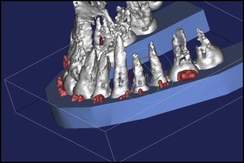
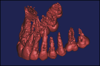
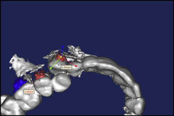
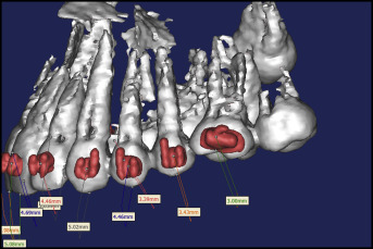
With the thresholding option, the images were enhanced, and the teeth were isolated to gain a clear view of their roots ( Fig 1 ). With both images in the Mimics image-processing software, each bracket was placed on its designated tooth and positioned accurately using the Mimics software tools. The ability to clearly visualize both the crown and the root of every tooth together with precise dimensional measurements allowed for accurate positioning of the brackets, with particular attention to the root axes, aiming for root parallelism at the end of the treatment ( Figs 2-4 ).
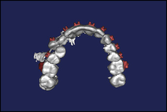
After the brackets were placed, a 3D image of a U-shaped stent was added to the project. Then the image of the stent was placed over the teeth and half of the brackets, leaving the other half of the brackets uncovered. In the Mimics software, the teeth and brackets were then subtracted from the image of the tray to have a negative replica. The subtracted image of the tray in stereolithography format was printed with a 3D printer (FORMIGA P110; EOS e-Manufacturing Solutions, Krailling, Germany) to obtain a 3D printed bracket positioning tray with indentations for bracket seating ( Figs 5-7 ). The printer uses additive manufacturing, laser sintering, and 3D printing. In additive manufacturing, components are built in layers by depositing materials guided by the digital 3D design. The material used to construct the stereolithographic tray was polyamide (PA 2200; EOS, Novi, Mich), which is characterized by high strength and stiffness, good chemical resistance, high detail resolution, and biocompatibility. The actual brackets were then conveyed to the printed trays, and the whole assembly was ready for direct bonding in the patient’s mouth ( Fig 8 ).