Introduction
Moment-to-force ratios (M:F) define the type of tooth movement. Typically, the relationship between M:F and tooth movement has been analyzed in a single plane. Here, to improve the 3-dimensional tooth movement theory, we tested the hypothesis that the mathematical relationships between M:F and tooth movement are distinct, depending on force system directions.
Methods
A finite element model of a maxillary first premolar, scaled to average tooth dimensions, was constructed based on a cone-beam computed tomography scan. We conducted finite element analyses of the M:F and tooth movement relationships, represented by the projected axis of rotation in each plane, for 510 different loads.
Results
We confirmed that a hyperbolic equation relates the distance and M:F; however, the constant of proportionality (“k”) varied nonlinearly with the force direction. With a force applied parallel to the tooth’s long axis, “k” was 12 times higher than with a force parallel to the mesiodistal direction and 7 times higher than with a force parallel to the buccolingual direction.
Conclusions
The M:F influence on tooth movement depends on load directions. It is an incomplete parameter to describe the quality of an orthodontic load system if it is not associated with force and moment directions.
Highlights
- •
Finite element simulations of load systems were performed on a maxillary premolar.
- •
The tooth’s center of rotation was calculated for each scenario.
- •
Tooth movement had a nonlinear dependency on the force system’s features.
Evaluating the effectiveness of the loads delivered by an orthodontic device onto the teeth is a challenging task. Complex load systems that act simultaneously in all 3 spatial planes are expected during orthodontic treatment. The initial analysis of relationships between 3-dimensional (3D) tooth movement and loads is possible by discrimination of moment-to-force ratios (M:F) in each planar projection. In 3 dimensions, each M:F is defined by combinations of the forces contained in the plane and the moments perpendicular to it. Unfortunately, even if all information is provided to an orthodontist about the 3D force system on a specific tooth, extremely limited 3D information is currently available on how the tooth will actually move. This occurs because studies on the relationship between M:F and the center (axis) of rotation (C.Rot) are typically limited to 1 plane and 1 force direction. Because of the morphologic asymmetry of teeth, it is reasonable to hypothesize that each 3D permutation of M:F in a different direction has a different mathematical relationship with the patterns of tooth movement.
The most common method to describe the type of tooth movement consists of measuring the distance from the tooth’s projected axis of rotation (C.Rot) to the virtual intersection of the axes of resistance (center of resistance [C.Res]). Previous authors have evaluated the influence of controlled M:F increments on the type of tooth movement in 1 plane. One study focused on applying a force perpendicular to a canine’s long axis with a parabola-shaped root, obtaining the so-called Burstone formula (M:F = 0.068* h 2 /D), where h is the distance from the alveolar crest to the apex, and D is the distance between the C.Res and the C.Rot. Authors of all previous finite element studies have analyzed the movement in a single plane, except for Viecilli et al, who analyzed loads in the 3 planes and how they affect the axes of resistance. One experiment studied the maxillary premolar and canine, evaluating the effects of different M:F under constant force and of different forces under constant M:F. The authors found that the force value influences the type tooth movement; ie, even with the same M:F, movement is different if the force increases. This happens because of the nonlinear behavior of the periodontal ligament (PDL), which becomes important after a certain strain threshold.
Here, we tested the hypothesis that the mathematical relationships between M:F and tooth movement are distinct, depending on the force direction. To do so, we built a comparative map of the effects of relevant M:F combinations on a maxillary first premolar that can also be useful to help plan tooth movement.
Material and methods
A model composed of tooth, ligaments, and alveolar bone structures was created by digital integration of a cone-beam computed tomography (CBCT) scan and a surface-structured light scan. An optical scanner was used to reconstruct the tooth crown by digitalization of the plaster casts. The 3D individual dental tissues obtained by the optical scanner and the CBCT sensor were fused to create a multibody orthodontic model with minimum user interaction. The fusion of the multimodal data sets allows the most accurate representation for each tissue: ie, tooth crown by optical scanning and tooth root and alveolar bone by CBCT imaging. The obtained geometries were auto-patched to create trimmed nonuniform rational basis spline (NURBS) surfaces, which were converted into vendor-neutral file format allowing the exchange of computer-aided design models “IGES” (Initial Graphics Exchange Specification). A linear elastic model was used for each structure to test the movements under the assumption of PDL strains less than 7.5%.
The PDL was created manually because it is not always readily discernible in a CBCT volume because of its low thickness. The tooth and bone were dilated uniformly by 0.2 mm, and the dilated parts were intersected to create the PDL as a uniform thick layer. The tooth dimensions were scaled to reflect an average premolar.
The dentoalveolar complex includes teeth, PDLs, gingival tissues, and alveolar bone. Here, the bone and the tooth were modeled as homogenous bodies without discerning between cortical and cancellous bone and enamel, pulp, and dentin because of their high stiffness compared with the PDL. Moreover, congruent with the rest of the literature, the gingival tissue was not accounted for in the finite element model since it does not affect the final result because of its extremely low stiffness compared with tooth and bone. This simplification, which was also made in previous studies, allowed us to save computational time without compromising the testing of our hypothesis under the specified load thresholds. Young’s moduli of 20000 MPa and 2000 MPa were assigned to the tooth and the bone, respectively. The Poisson ratio was 0.3 for both.
The geometries were imported in the finite element software, Workbench 16 (ANSYS, Canonsburg, Pa), where the 3 bodies were meshed with solid elements resulting in 140831 quadratic tetrahedral elements and 234955 nodes ( Fig 1 , A ).
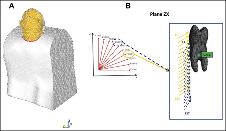
To find the references for tooth translation, 3 simulations were run, applying a moment of 1.5 N·mm parallel to each coordinate system axis to the tooth. The approximate 2-dimensional projections of the axes of resistance (C.Res) for the 3 simulations were recorded according to a methodology previously published. After iteratively refining the mesh in the region until reaching an edge size of 0.1 mm, the average position of the C.Res was recorded and used for further analysis.
The different M:F tested were applied at the C.Res because several appliances, such as orthodontic aligners, do not use brackets. It is possible to obtain the equivalent M:F at the bracket knowing the distance between the bracket and the C.Res. In the case of a maxillary first premolar, sized according to Table I , the bracket center was located 4.5 mm below the incisal edge. The distances from the C.Res were 10.3, 3.8, and 0 mm in the vertical, linguobuccal, and mesiodistal directions, respectively. The equivalent M:F at the bracket can be obtained with the following equations, which also account for the force direction (defined in Fig 1 , B ).
Plane ZX: M F Bracket = M F C .Res + 3.8 + 10.3 ⋅ tan ( Force Direction ) 1 + tan ( Force Direction ) 2
Plane YZ: M F Bracket = M F C .Res − 10.3 1 + tan ( Force Direction ) 2
Stay updated, free dental videos. Join our Telegram channel
VIDEdental - Online dental courses


