Introduction
In this study, we aimed to evaluate the effects of maxillary protraction using traditional labiolingual arches and implant-type protraction devices before orthopedic treatment of patients with skeletal Class III malocclusion.
Methods
A 3-dimensional finite element model of the maxillofacial bones with high biologic similarity and including the sutures was constructed. Through stress and displacement calculations, a biomechanical study was performed for the maxillofacial bones, mandible, and sutures.
Results
We quantified detailed changes in the sutures with 2 protraction methods to analyze their effects on the growth of the maxillofacial bones.
Conclusions
(1) The labiolingual arch is suitable for skeletal Class III patients with crossbite and deep overbite. The frontomaxillary and zygomaticomaxillary sutures played major roles in the forward displacement and counterclockwise rotation of the maxilla. The temporozygomatic and pterygopalatine sutures did not change significantly. (2) The implant type of protraction device is suitable for skeletal Class III patients with crossbite and open bite. Both the frontomaxillary and zygomaticomaxillary sutures played decisive roles in the forward displacement and clockwise rotation of maxilla. The temporozygomatic and pterygopalatine sutures showed small changes. (3) The labiolingual arch caused less stimulatory growth on the maxilla, whereas the implant caused greater stimulatory growth on the maxilla. Protraction with the labiolingual arch is more suitable for early skeletal Class III patients at a younger age; protraction with an implant is applicable to skeletal Class III patients in the late mixed dentition or early permanent dentition.
Highlights
- •
A 3-dimensional finite element model of the maxillofacial bones was constructed.
- •
Two protraction methods were simulated.
- •
Changes in the sutures were quantified to assess growth of the maxillofacial bones.
- •
This research supports orthopedic treatment of skeletal Class III malocclusions.
- •
It is important to properly evaluate a problem before orthopedic treatment.
Skeletal Class III malocclusion is a common dental abnormality. This problem, which is primarily caused by the insufficient development of the maxillary bone, tends to worsen with age. Applying maxillary protraction can effectively direct the maxillary bone to grow forward, and the effect of this procedure has been widely acknowledged. Among traditional protraction devices, the labiolingual arch has a superior effect. However, when this appliance guides the maxillary bone to grow forward, the maxillary anterior teeth also inevitably incline to the lip side: ie, the dental effects become stronger than or equal to the bone effects. The labiolingual arch is applied in the orthopedic treatment of crossbite accompanied by a deep overbite occlusion. For skeletal Class III malocclusion patients with an open-bite tendency, the maxillary bone should be rotated clockwise during orthodontic treatment; the bone effects should be stronger than the dental effects. This condition cannot be achieved using traditional protraction devices. Moreover, applying an implant type of protraction appliance can solve these problems. Based on the study of Smalley et al, the bone effects of maxillary protraction with implants should be significantly stronger than the dental effects.
To evaluate traditional maxillary protraction and implant-type protraction devices from the perspective of biomechanics, as well as to provide clinical treatment guidelines, in this study we first constructed a 3-dimensional (3D) finite element model of the maxillofacial bones with high biologic similarity and including the sutures. The model was designed to simulate labiolingual arch loading and implant-type maxillary protraction appliances. Second, stress and displacement values were obtained through calculations. Third, a biomechanical study was performed for the sutures, the maxillofacial bones, and the mandible. We quantified the detailed changes in the sutures with 2 protraction methods to analyze the effects of these methods on the growth of the maxillofacial bone, particularly on the 4 sutures that are closely related to the growth of these bones. Finally, an in-depth discussion is provided based on our results.
Material and methods
This study was approved by the medical ethics committee of the Hospital of Stomatology, Jilin University, in China.
First, we established a 3D finite element model of the maxillofacial bones with a physical model of the sutures. A 16-year-old Asian volunteer with normal occlusion, good periodontal health, and no temporomandibular joint (TMJ) disease was chosen to be the model.
The volunteer’s craniofacial complex was consecutively scanned in multislices in the normal way. In the process of scanning, the volunteer was required to lie on her back with her chin lifted, her head fixed, and her mouth open slightly, and bite a premade 2-mm-thick plastic piece to keep the teeth apart. Her bite plane was identified, and the scanned slice was parallelized with the bite plane. Scan parameters were tube voltage, 120 kV; electric current, 250 mA; bed speed, 0.8 seconds per circle; slice thickness, 0.67 mm; and interval, 0.33 mm. We obtained 456 images by cleaning up the computed tomography (CT) DICOM data from the scans and recorded them on compact disks.
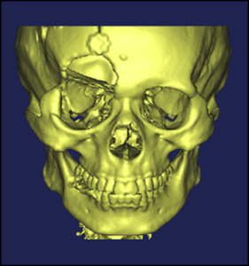
The CT data output in BMP format was transferred to Mimics software (version 10.0; Materialise, Leuven, Belgium), a medical visualization software and a rectangular coordinate system with the x-, y-, and z-axes built up according to slice image data from the CT scans (x-axis indicates axial; y-axis, sagittal; z-axis, coronal). For each slice’s CT image, its outline map was formed into a closed outline curve. Then, based on the 0.33-mm interval between CT slices, each outline that represented a CT scan slice was transferred to its position according to its z-value, and a rough 3D model of the maxillofacial bones was automatically built using the 3D modeling function of the Mimics software ( Fig 1 ). Based on this model, a new 3D finite element model of the maxillofacial bones was generated after deleting the unnecessary skull part, removing the constructed defects between the teeth, separating the maxillary and mandibular dentitions, and smoothing the surface. The right orbital rim of this model had some defects caused by low and irregular bone density; these defects were fixed during the finite element modeling.
The 3D STL model built was imported to software (Geomagic, Rock Hill, SC), a professional reverse-engineering software. An incision on the maxillofacial bones was determined by Boolean calculation along the track of the sutures on it, and the basic NURBAS (Non-Uniform Rational B-Splines) surface model which is necessary to the analysis was obtained.
Surface element data that were corrected in Geomagic were imported to ICEM CFD software (ANSYS, Canonsburg, Pa) at the same time that the surfaces corresponding to the frontomaxillary, zygomaticomaxillary, temporozygomatic, and pterygopalatine sutures were built up on the model of the maxillofacial bones, and filling elements were divided according to surface of model on the basis of the octree element technique.
On the basis of an initially formed tetrahedron net, a 1-mm-thick prismatic net was formed through the projections of the frontomaxillary, temporozygomatic, and pterygopalatine suture trends on the characteristic face; thus, a 3D finite element model with solid models of the sutures was formed. We selected the grids of corresponding faces at the malomaxillary suture and generated a zygomaticomaxillary suture grid in the direction of a normal vector.
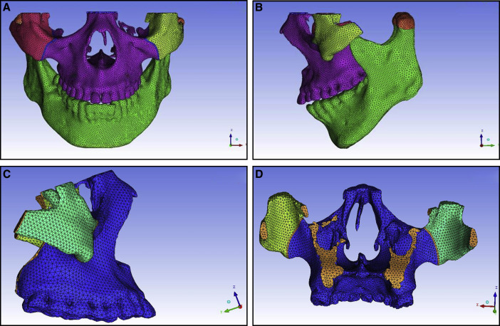
Finally, we obtained a 3D finite element model of the maxillofacial bones with 86757 nodes and 485915 cubes, including a physical model of the frontomaxillary, zygomaticomaxillary, temporozygomatic, and pterygopalatine sutures ( blue lines in Fig 2 ). We imported the repaired STL into the ICEM CFD software for meshing and assigned values to the material properties according to the final geometric structure. Table I shows the assignments of the modulus of elasticity and Poisson’s ratio.
| Part | Modulus of elasticity (MPa) | Poisson’s ratio |
|---|---|---|
| Bones | 1.37 × 10 4 | 0.30 |
| Teeth | 2.07 × 10 4 | 0.30 |
| Sutures | 38.6 | 0.45 |
The principle of the design of an intraoral device for labiolingual arch protraction is to connect the entire maxillary dental arch into a whole to reduce the tooth effect. According to this, the model was simplified without cutting the maxillary teeth to simulate the intraoral device using a labiolingual arch. The protraction mask was connected directly to the chin to simulate the chin support. Finally, a 3D finite element model of the maxillofacial region with the intraoral device for labiolingual arch protraction was established ( Fig 3 ).
The protraction model with the implant was simplified by applying the point between the root apices of both maxillary canines and first premolars as the traction point. The model of the extraoral protraction mask previously described was used ( Fig 3 ).
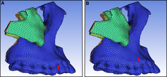
In the labiolingual arch protraction model, the maxillary arch was considered as a whole, and the action point of protraction was set between the maxillary canine and the first premolar ( Fig 4 , A ). In the protraction model with the implant, the action point was set between the root apices of both maxillary canines and first premolars ( Fig 4 , B ); ie, the implant achieved 100% osseointegration with the maxillary bone. The materials used in protraction were spring units; the other extraoral protraction mask was made of rigid materials. According to the lever principle, the reaction force generated by protraction was mostly transmitted to the mandible through the mask.
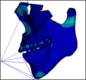
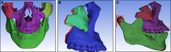
The growth of the maxilla is mainly accomplished through bone deposition at the frontomaxillary, zygomaticomaxillary, temporozygomatic, and pterygopalatine sutures. Except for the zygomaticomaxillary suture, the other 3 sutures are all located on the edges of the maxillofacial bones. Therefore, the boundary constraints with zero displacement and zero rotation were applied on the tangent lines of the outer margins of the frontomaxillary, temporozygomatic, and pterygopalatine sutures ( Fig 5 ). The mandible was included in the model. The TMJ connection between the mandible and the maxilla was set as absent. Two tangent lines from condylion and the protrusion of the outer margin of the condylar process were made, respectively. The boundary constraints with zero displacement and zero rotation were applied on the 2 tangent lines.
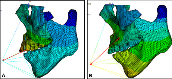
In the labiolingual arch protraction model, the action point was set at adjacent points of both maxillary canines and first premolars to simulate the position of the protraction hook. In the protraction model with the implant, the action point was set between the root apices of both maxillary canines and first premolars to simulate the implant. In both methods, 800 g of protraction force was applied on both sides at a 20° to 30° angle with respect to the occlusal plane, depending on the position of the lower lip ( Fig 6 ).
Results
Displacement nephograms along the y-axis and z-axis after loading of the protraction model using the labiolingual arch and the implant are shown in Figures 7-10 . The x-axis representing the horizontal displacement, which was not the displacement considered in protraction, was ignored.
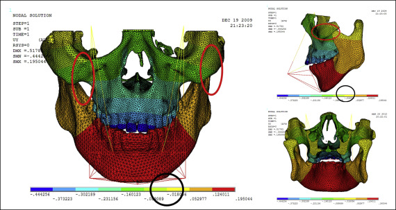

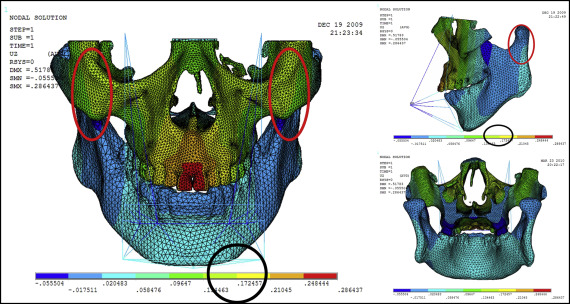
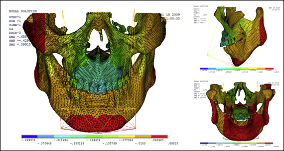
The forward direction of the y-axis indicates a negative value, and the backward direction of the y-axis indicates a positive value; the upward direction of the z-axis indicates a positive value, and the downward direction of the z-axis indicates a negative value. The displacement distributions along the y-axis and z-axis were obtained by the data extraction function of the ANSYS software ( Table II ).
| Part | Displacement along y-axis | Displacement along z-axis | ||
|---|---|---|---|---|
| Labiolingual arch | Implant | Labiolingual arch | Implant | |
| U1 point in the incisal edge of maxillary central incisor | −0.444 | −0.163 | 0.249 | −0.312 |
| A-point of maxilla | −0.302 | −0.275 | 0.210 | −0.253 |
| L1 point in the incisal edge of mandibular central incisor | 0.124 | 0.395 | −0.018 | −0.018 |
| Pogonion of mandible | 0.124 | 0.395 | 0.205 | 0.040 |
| Frontomaxillary suture | −0.160 | −0.164 | 0.205 | −0.077 |
| Malomaxillary suture | −0.160 | −0.275 | 0.134 | −0.018 |
| Temporozygomatic suture | −0.018 | −0.164 | −0.018 | −0.018 |
| Pterygopalatine suture | −0.018 | −0.052 | −0.018 | −0.018 |
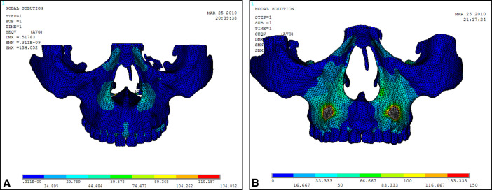
Stress distribution nephograms of the maxilla in the protraction modes using the labiolingual arch and the implant were calculated ( Fig 11 ). The 4 sutures were extracted to obtain the stress distribution nephograms ( Fig 12 ). As shown in Table III , the suture stress distributions of the 2 types of protraction were statistically analyzed and compared.