Ever since the first dental radiographic image was introduced in the early 1900s, the technology of dental radiology has expanded rapidly. Radiation dosage to patients has been minimized, and the various types of radiographic imaging used by dentists have expanded. Since the advent of dental implantology, radiographic evaluation of potential implant sites has changed as radiographic technology advances.
Radiographic evaluation, as in all aspects in radiology, is an important adjunct to a thorough physical exam. It is important to remember that even with the current use of three-dimensional reconstructions for implant treatment planning, the practitioner should not dismiss the importance of the physical examination. Visual inspection and palpation of the potential implant site should provide initial clues to ridge characteristics and bone width. The overlying gingival and dental health of the patient should be ascertained during the history and physical exam.
With success rates of dental implants exceeding 90%, the use of dental implants is becoming the treatment of choice for restoration of edentulous areas. Endosteal implants have been shown to be effective in restoring single teeth and edentulous areas in addition to restoration of the maxillary and mandibular edentulous arches. All therapeutic restoration options should be explored and discussed with the patient. Once the decision is made to restore with dental implants, the selection of an appropriate radiographic modality should be determined based on the relevant anatomy of the area to be restored. The various modalities for radiographic evaluation including their advantages and disadvantages will be discussed.
▪
RADIOGRAPHIC PRINCIPLES FOR IMPLANTOLOGY
Patients evaluated for dental implants usually require one or a combination of all available radiography used in the field of dentistry. Previously, patients were evaluated using panoramic, intraoral, and cephalometric techniques or tomography. These techniques possess an inherent distortion based on either magnification or patient positioning. A recent increase has been noted in the use of conventional and computed tomography for implant evaluation. Software systems have been designed for these methods specific to implant placement.
In the selection of radiographs for implant evaluation, the practitioner should abide by the basic principles of radiography. First, an adequate number of images should be taken to provide all necessary anatomic information. In implantology, this includes the amount and type of bone, which requires multiple images at perpendicular angles. Second, the imaging technique chosen should be precise and dimensionally accurate. Patient positioning should be standardized to allow comparison of preoperative and postoperative images. Third, the location of the images should be reproducible in the patient’s anatomy. This is usually accomplished via radiopaque markers or stents in edentulous regions or via the existing dentition ( Figure 34-1 ). Fourth, the chosen techniques should minimize distortion, whether positional or related to artifacts on the imaging surface. Lastly, the radiation dosage and cost to the patient should be minimized. If more than one assessment system can be used with minimal disparity in diagnostic information, the ALARA (as low as reasonably achievable) principle should preside. This refers to minimizing the patient’s exposure to the radiation necessary to obtain an adequate radiographic assessment.
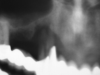
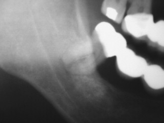
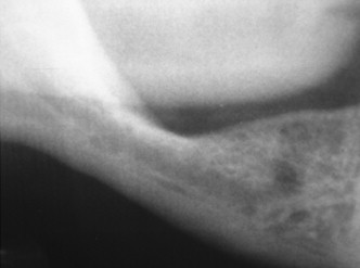
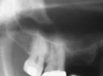
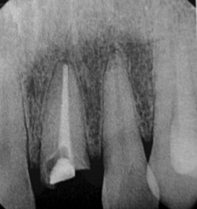
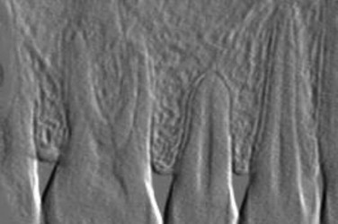
The use of radiography for dental implants is primarily focused on obtaining pertinent diagnostic information related to their placement. Several criteria for placement of implants are based on information obtained during various radiographic techniques. Ideally, the radiographic technique used should be able to identify several critical factors about the implant site. The presence of disease, such as cysts, periapical lesions, and intraosseous pathologic conditions, should be easily identified ( Figure 34-2 ). The location of critical anatomic structures and their relationship to the alveolus should also be easily identified and their distances accurately measured ( Figures 34-3 through 34-7 ). Osseous morphology, such as knife-edge ridges, location of the submandibular fossa, anatomic variations, abnormal marrow spaces, and cortical thickness, should be easily visualized. The type, orientation, and amount of available bone and its orientation are crucial in treatment planning for implant location.
The bone quality has been assessed in using several systems. One of the most widely recognized is the system proposed by Lekholm and Zarb. In this system, bone is classified into four classifications based on the relative amounts of cortical and trabecular bone. In the first classification, almost the entirety of bone is composed of compact cortical bone. In the second classification, compact trabecular bone is surrounded by a thick layer of cortical bone. The third classification is described as a thin layer of cortical bone encompassing high density trabecular bone with favorable strength properties. Finally, in the fourth and least desirable bone type, a thin layer of compact bone surrounds loosely arranged trabecular bone.
To identify the bone type, cross-sectional imaging is necessary. In 1996, Lindh et al. proposed a system of identifying bone quality based on periapical radiographs. This system describes the bone quality by identifying and categorizing the trabeculation of the bone on periapical radiographs and is reserved for medullary bone only. The bone is described as having dense, sparse, or alternating dense and sparse orbicular regions. Although this technique does not require cross-sectional imaging, it is less specific in its categorization.
▪
PLAIN FILMS (PERIAPICAL, OCCLUSAL, AND CEPHALOMETRIC EVALUATION)
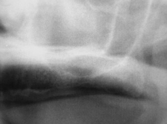
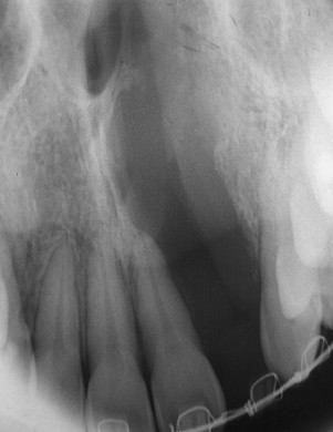
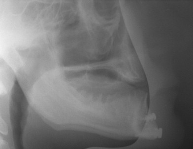
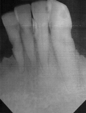
Intraoral radiographs, such as periapical and occlusal radiographs, reproduce detailed anatomy of the proposed implant site ( Figures 34-8 and 34-9 ). Trabecular patterns and relationships to anatomic structures, such as adjacent roots, can be accurately reproduced. Low cost, ease of availability, high resolution, and patient acceptance make periapical and occlusal radiographs a good choice for initial evaluation. However, image reproducibility is rarely precise, and these images lack any cross-sectional data, often vital in implant treatment planning ( Figure 34-10 ). Despite these drawbacks, periapical radiographs continue to be used postoperatively to monitor crestal bone height changes.

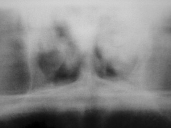
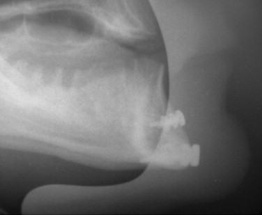
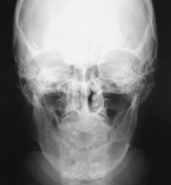
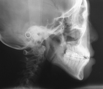
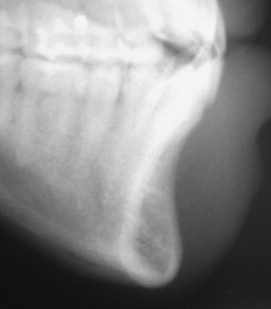
Cephalometric evaluation, either lateral or anteriorposterior evaluations, can be useful in treatment planning for implants. These images can provide angulations, bone height and thickness, and soft tissue profiles ( Figures 34-11 and 34-12 ). They also offer skeletal jaw relationships and the relation of the maxilla and mandible. A lateral cephalogram in particular is often crucial in determining whether or not an edentulous patient can be reconstructed with dental implants. Orthognathic surgery may be recommended before implant reconstruction to relieve the increased occlusal forces often present when restoring patients without a Class I jaw relationship. Several disadvantages dominate cephalometric films. First, only the anterior mandible is visible in cross-sectioning ( Figures 34-13 and 34-14 ). In both the anterior and lateral views, a majority of the maxilla and mandibular dentition and osseous structures overlap, producing distortion and inaccuracy of measurement ( Figure 34-15 ). Patient positioning is also difficult to reproduce for purposes of comparison.


▪
PLAIN FILMS (PERIAPICAL, OCCLUSAL, AND CEPHALOMETRIC EVALUATION)
Intraoral radiographs, such as periapical and occlusal radiographs, reproduce detailed anatomy of the proposed implant site ( Figures 34-8 and 34-9 ). Trabecular patterns and relationships to anatomic structures, such as adjacent roots, can be accurately reproduced. Low cost, ease of availability, high resolution, and patient acceptance make periapical and occlusal radiographs a good choice for initial evaluation. However, image reproducibility is rarely precise, and these images lack any cross-sectional data, often vital in implant treatment planning ( Figure 34-10 ). Despite these drawbacks, periapical radiographs continue to be used postoperatively to monitor crestal bone height changes.


Cephalometric evaluation, either lateral or anteriorposterior evaluations, can be useful in treatment planning for implants. These images can provide angulations, bone height and thickness, and soft tissue profiles ( Figures 34-11 and 34-12 ). They also offer skeletal jaw relationships and the relation of the maxilla and mandible. A lateral cephalogram in particular is often crucial in determining whether or not an edentulous patient can be reconstructed with dental implants. Orthognathic surgery may be recommended before implant reconstruction to relieve the increased occlusal forces often present when restoring patients without a Class I jaw relationship. Several disadvantages dominate cephalometric films. First, only the anterior mandible is visible in cross-sectioning ( Figures 34-13 and 34-14 ). In both the anterior and lateral views, a majority of the maxilla and mandibular dentition and osseous structures overlap, producing distortion and inaccuracy of measurement ( Figure 34-15 ). Patient positioning is also difficult to reproduce for purposes of comparison.


▪
DIGITAL RADIOGRAPHY
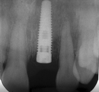
With the advent of digital radiography, it is now possible to assess implant sites preoperatively and postoperatively with digital imaging. Studies have shown that digital imaging is as accurate as plain film radiography in its assessment for bone levels and distances from anatomic structures. The transfer of these digital images to paper or analog film does not affect the accuracy of the assessment ( Figure 34-16 ). Software programs for periapical and occlusal digital images allow for the manipulation of the images to show greater anatomic detail in some cases ( Figure 34-17 ). The technique for digital imaging of implant sites does not differ significantly from that of plain film intraoral radiographs, although the radiation dosage is reduced by 75% to 90% with digital radiographic techniques.
Proposed advantages of digital radiography when compared with traditional plain film techniques are based on the increased speed and elimination of developing x-rays. Software systems for digital radiographic images allow for pseudo–three-dimensional evaluation, alteration in color, contrast, and image rotation. Linear measurements may also be made on the computerized image. These features, although useful, do not eliminate the inherent variance in patient positioning and lack of cross-sectional data. The disadvantages of traditional film radiographs, which would require supplemental imaging, are still present with digital imaging.
▪
SUBTRACTION RADIOGRAPHY
Subtraction evaluation of implant placement uses two radiographic images and a digital computerized assessment of changes between them. It allows for definitive evaluation of postoperative bone loss or gain over time. Radiographic density changes in the periimplant bone matrix may also be visualized. The immediate postoperative radiograph is used to compare bone heights over follow-up visits. The subtraction technique may also be useful in visualizing early vertical and periimplant bone loss. Currently, this technique is not widely used because of high implant success rates, operator preference, and cost-effectiveness. Mechanical techniques to assess osseointegration combined with standard postoperative radiographic examination continue to be the standard of care.
▪
ORTHOPANTOMOGRAM
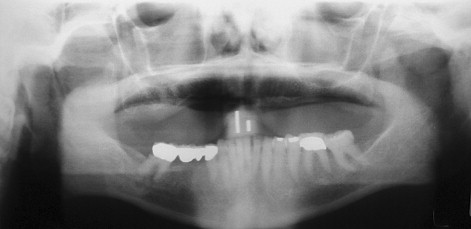
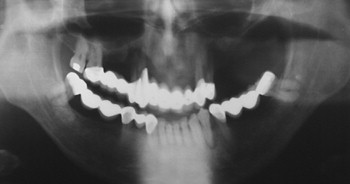
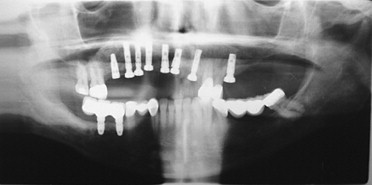
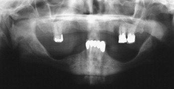
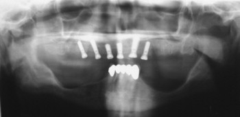
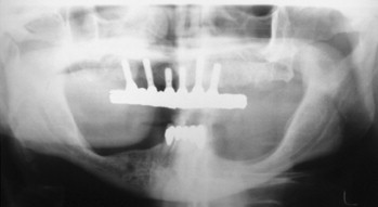
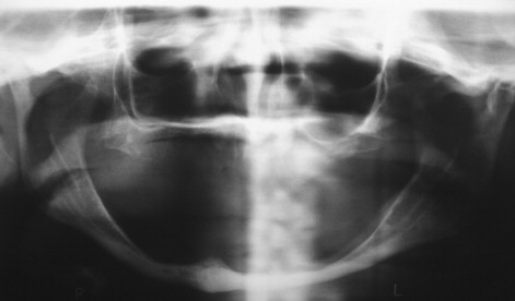
Panoramic evaluation is part of the current standard of care for implant site evaluation and follow-up assessment. Advantages of panoramic films include visualization of all anatomic structures of the maxilla and mandible, low cost to the patient, and availability to the practitioner ( Figures 34-18 through 34-22 ). Disadvantages include variance in magnification in the horizontal plane, positioning artifacts, and lack of cross-sectional imaging. Projection geometry also causes lingual structures to be oriented superior to structures of facial position distorting their relationship in the vertical plane. Vertical magnification on panoramic images is usually uniform and is able to be assessed and accommodated via markers of known length placed at the time of radiographic imaging (see Figure 34-1 ). Horizontal plane magnification, however, varies widely based on the location in the dental arch, distance and position related to the focal trough, and patient positioning. Some panoramic machines are able to produce cross-sectional imaging via curved layer tomography. This mechanism usually produces thicker image layering, lower detail, and increased distortion when compared with linear or conventional tomography. Despite these disadvantages, the information obtained in this manner is adequate in many cases, but may not be useful in areas of decreased bone quantity ( Figure 34-23 ). In these instances, the cross-sectional imaging is more critical for assessment of the implant site.
▪
LINEAR TOMOGRAPHY
Linear tomography may be used when evaluating implant sites for the assessment of the area in cross-section. In regions of the mandible and maxilla where proximity to anatomic structures may dictate implant size and placement, such as the regions of the inferior alveolar nerve, maxillary sinus, and nasal fossa concavity, this cross-sectional information is important in appropriate treatment planning. Linear tomography uses coordinated film and x-ray beam movement to create thin slices of the desired area to be viewed. Advantages of conventional tomography include moderate expense, uniform magnification, cross-sectional imagery, and reproducibility when used with a positioning device. Several devices are available for reproducible patient positioning, such as the cephalostat, laser positioning system, and plastic positioning devices. Disadvantages of these systems include limited availability, increased time for image production when compared with panoramic imaging, and difficulty in image interpretation when not combined with a software program. Some form of radiopaque marker is necessary for relating the cross-sectional image to patient anatomy. Tomographic abilities are currently being added to commercially available panoramic machines.
▪
COMPUTED TOMOGRAPHY
The start of three-dimensional imaging was in 1917 when the Austrian J. H. Radon proved that the image of a three-dimensional object could be calculated from an infinite number of two-dimensional projections called back projection. Sir Godfrey Hounsfield conceived the first primitive computed tomography (CT) scanner in 1948, but the concept failed as a result of mathematic calculations that were too taxing for the technology of that time frame. The attenuation coefficient of a slice of an object from a series of projections was first computed by Allen M. Cormack in the Journal of Applied Physics in 1964. Hounsfield first described the original CT scanner manufactured by the British engineering and recording firm EMI in 1972. Hounsfield and Cormack shared the Nobel Prize for medicine for these developments.
The original EMI CT scanner was designed to make cross-sectional images of the brain. There were two detectors and a tube that moved parallel from side to side across a specialized hollow round mounting bracket called a gantry. The tube and detectors rotated 1° and traversed again for 180°. Maximum resolution of the initial scans was 1 cm. Calculations created an image of 80 rows of 80 picture elements called pixels. The original CT scanners were named computerized axial tomography (CAT) scanners because they were designed to acquire images in the axial plane with the patient in a dorsal position on the table. The host computer calculated algorithms that could produce image data in the coronal and sagittal planes.
Coronal CT scans were first described in 1978. These scans were used to view the sinuses and orbits. They can be acquired on a CT scanner by tilting the gantry maximally to a negative 30° and having the patient lay prone with the neck hyperextended. Coronal CT scans have a disadvantage for dentistry, especially when metallic restorations are present. Scatter is produced that creates extreme streak artifacts throughout the scan ( Figure 34-24 ). Three-dimensional calculations that will be further described later in the chapter are meaningless with gantry positions other than 0°. This is due to the fact that voxels are rectangular in CT scanners. Cone beam technology, which also will be described later in the chapter, is based on perfectly cubic voxels and does not have this disadvantage in three-dimensional calculations. Height measurements of the dental alveolar ridge are exaggerated in coronal CT scans, especially in areas of arch curvatures, such as the canines.
Stay updated, free dental videos. Join our Telegram channel
VIDEdental - Online dental courses


