With storage phosphor plates, the energy deposited by x-ray photons is stored within the phosphor. This energy is released when the phosphor is stimulated with a visible wavelength laser light.
7. Which radiosensitive organs are in the field of typical dental x-ray examinations?
The thyroid is an extremely radiosensitive organ, along with lymphoid tissue and bone marrow in the exposed areas.
8. What evidence suggests a risk of carcinogenesis from exposures to low levels of ionizing radiation such as those in dentistry?
No single study has proven the association between carcinogenesis and exposure to x-rays at the low levels used in dentistry. Many studies that follow patients exposed to higher levels, however, provide evidence of a link. Populations that have been studied include atomic bomb survivors in Nagasaki and Hiroshima, radium watch dial painters, and patients exposed to multiple fluoroscopies for tuberculosis.
9. What units are used to describe radiation exposure and dose? What do they measure?
1. The roentgen (R) is the basic unit of radiation exposure for x-rays and gamma radiation. It is defined in terms of the number of ionizations produced in air. It is a measure of the amount of radiation to which a person has been exposed, but does not measure how much radiation was absorbed.
2. The rad (roentgen-absorbed dose) is a measure of the amount of energy absorbed by an organ or tissue. Different organs or tissues absorb a different amount of energy when exposed to the same amount of radiation or roentgens.
3. The rem (roentgen equivalent, man or mammal) is a measure of the degree of damage caused to different organs or tissues. Different organs or tissues show differing amounts of damage even when they have absorbed the same amounts of rads.
The International System of Units (SIs) are the coulomb/kilogram (C/kg), gray (Gy), and sievert (Sv) for the roentgen, rad, and rem, respectively.
10. What is the difference between density and contrast?
Density refers to the overall degree of blackening of a film. Contrast refers to the differences in densities between adjacent areas of film.
11. Which technique factors control film density?
The longer a sensor is exposed, the darker it will be; hence, time of exposure controls density. The milliampere (mA) determines how hot the filament gets and how many electrons are boiled off. The higher the filament current, the hotter the filament and the more electrons are boiled off to reach the anode and produce x-rays; hence, mA also controls density. As a result of the kilovolt peak (kVp), which is the potential voltage difference between the cathode (filament) and anode, electrons that are boiled off are accelerated to the anode. The greater the potential difference between the cathode and anode, the greater the acceleration of the electrons toward the anode. Electrons that hit the anode at higher speed result in x-rays with higher energies. X-rays with higher energies are more likely to reach the sensor and darken it. Thus, kVp also controls sensor density. The distance from the source to the sensor also has a great effect on sensor density (see question 16).
12. Which technique factors control film contrast? How do they affect contrast?
Contrast is controlled by the kVp only. The higher the kVp, the lower the contrast, and vice versa. Time, mA, and distance affect only density and not contrast.
13. What is cone beam CT (CBCT), and how does it differ from medical or conventional CT in acquiring the images?
CBCT is a relatively new (c. 2000) computed tomograpic imaging modality that is able to provide three-dimensional images of anatomic structures. Unlike medical CT, in which the data are acquired axially by a thin, fan-shaped beam, the beam in CBCT is shaped like a cone. The medical CT scanner acquires individual image slices, which are then stacked to obtain the field of view (FOV). CBCT, with its large cone-shaped beam, acquires all the data in a single rotation. Thus, whereas in medical CT the x-rays are parallel to one another, in CBCT the x-rays are divergent.
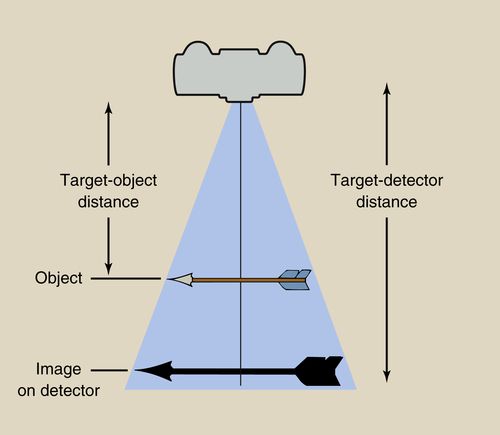
14. How is magnification defined? How do the target-detector and object-detector distances affect magnification?
Magnification is the ratio of the image size to the object size. It is, for example, the ratio of the length of the actual tooth as compared to the length of the tooth as measured on the monitor. In real life, it is rarely possible to measure the size—for example, whether it is length or width—of an object because the object is in the patient and is not visible at all (e.g. an impacted tooth, osseous landmarks on a lateral cephalogram) or is only partly visible (e.g. an erupted tooth). Thus, we use the formula

to calculate magnification (Fig. 5-2).
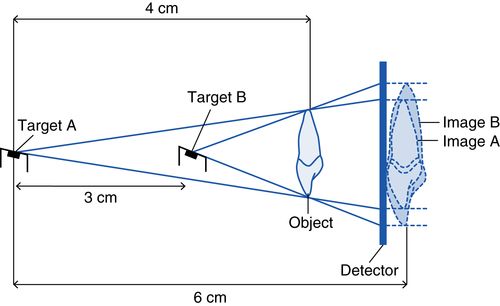
Figure 5-3 shows how to calculate magnification and how the target-detector and object-detector distances affect magnification. When the target (the target on the anode in the x-ray tube) is in position A, the target-detector distance is 6 cm and the target-object distance is 4 cm. Thus, the magnification is 6/4, or 1.5. If we move the target to position B, the target-detector distance is now 3 cm and the target-object distance is 1 cm. This shows how the target-detector distance affects magnification. All other factors remaining unchanged, the longer the target-detector distance, the less the magnification. This is the rationale behind using the long cone technique for intraoral imaging and the long distance in cephalometric radiography. Using the formula and Figure 5-3 as an example, you should now be able to determine how the object-detector distance affects magnification.
15. What is the ideal geometric setup to get the most accurate image in intraoral radiography?
The central x-ray should be perpendicular to the long axis of the object (e.g., tooth, head) and the long axis of the detector. To accomplish this, the long axis of the detector must be parallel to the long axis of the object.
Large target-detector distance: The longer this distance, the less the magnification (see question 14).
Small object-detector distance: The smaller this distance, the less the magnification (see question 14).
16. What is the inverse square law?
The intensity or exposure rate of radiation at a given distance from the source is inversely proportional to the square of the distance. If we double the distance from the source, for example, the intensity of the radiation is reduced fourfold. This is why the tube should be close to the patient and to the sensor to ensure that the image is not underexposed. The inverse square law can also be used to our advantage. By standing further away from the x-ray source, the intensity of the x-ray beam is reduced. Although the exact number may vary from state to state, generally if one stands 6 feet away from the dental x-ray source, no additional radiation protection is needed for the operator.
17. How do you trouble-shoot a radiographic image that is too dark (overexposed) or too light (underexposed)?
For film-based and digital systems, check the exposure factors (kVp, mA, time) to ensure that they are appropriate for the patient. For digital systems, one of these will almost always be the cause of the problem. With film, changes in radiographic quality usually result from errors in processing. For film-based systems check the chemicals to ensure that they are at the correct temperature, have been stirred, and are fresh. If all these factors are satisfactory, evaluation of the x-ray unit, digital sensor, or batch of film may be necessary.
Another error that may cause an underexposed image is failure to depress the x-ray exposure button for the duration of the exposure. It is not possible to overexpose an image by holding the exposure button too long because there is a fail-safe mechanism that will automatically stop the exposure after the time that was set. Placing the tube too far from the sensor will also result in an underexposed image because of the effects of the inverse square law (see question 16).
18. What is the difference between internal and external scatter?
When x-rays interact with material, including body tissues, a number of interactions may take place, including scatter (see question 3). Scatter may result from x-rays interacting with material outside the patient’s body and undergoing a change in direction so that the scattered photons hit the patient and thus increase the dose. This type of scatter is called external scatter. An example is an x-ray photon that hits the wall and is scattered in the direction of the patient. The second type of scatter is called internal scatter. This type of scatter occurs when x-ray photons interact with tissues in the patient and are directed to other parts of the patient’s body. Because these photons arise from interactions that occur in the patient’s body, they are known as internal scatter. An example is x-rays that interact with an object in the mouth (e.g., tooth restoration) and are scattered toward the thyroid gland. A lead apron and thyroid will not help reduce internal scatter.
19. How do we control scatter radiation in intraoral radiography?
In intraoral radiography, we do not control scattered x-rays after the fact—that is, we do not control scatter that results from the interaction of x-rays within the patient. We do, however, try to minimize scatter before the fact by using a lead-lined long cone, reducing the size of the x-ray field, and using as high a kVp as possible.
20. What is meant by the quality of an x-ray beam, and how it is measured?
The quality of the beam refers to the penetrating power of the beam. The penetrating power is greater the higher the energy values of the photons. X-ray beams have higher energy values, and the more penetrating, the higher the kVp. The word quality is a term of art and refers only to the energy level of the beam. The number of x-rays in a beam is described by the beam intensity. Although kVp may affect beam quality and intensity (quantity), the two parameters are distinct and separable.
Beam quality is measured by the half-value layer (HVL). The HVL is defined as that thickness of a given substance which, when introduced in the path of a given beam of rays, will reduce its intensity by half. Different materials have different half-value layers. The half-value layer also differs for different energy (kVp) beams.
21. What is meant by the terms sensitivity, specificity, and predictive value when applied to the efficacy of radiographic examinations?
Sensitivity refers to the ability of a test, in this case a radiograph, to detect disease in patients who have disease. Thus, sensitivity is a measure of the frequency of positive (true-positive rate) and negative (false-negative rate) test results in patients with disease. Specificity refers to the ability of a test to screen out patients who do not in fact have the disease. Thus, specificity is a measure of the frequency of negative (true-negative rate) and positive (false-positive) test results in patients without disease. The predictive value of a radiograph is the probability that a patient with a positive test result actually has the disease (positive predictive value) or the probability that a patient with a negative test result actually does not have the disease (negative predictive value).
22. What is the basic technology behind magnetic resonance imaging (MRI)?
Nuclei of atoms that have an unpaired proton or neutron in the body act like bar magnets. In the MRI procedure, the area to be examined is subjected to an external magnetic field. The long axes of the nuclei line up with the magnetic field. Once the nuclei are aligned, they are subjected to a radiofrequency (RF) pulse. They absorb some of the radio wave’s energy and lean over or tilt (the technical term is precess). When the RF pulse is turned off, the nuclei begin to return to their original energy state (relax) and emit the energy that they absorbed. This energy can be picked up by appropriate receivers and converted into a picture.
23. How does an MRI image produce tissue contrast so that one can distinguish between various types of tissue?
The operator selects the technical parameters of an MRI scan. The most important of these is the RF pulse sequence. The most basic characteristics of a pulse sequence are the repetition time (length of time between successive RF pulses) and echo time (how long after the RF pulse is applied when the magnetic resonance signal is read). The contrast is determined by the repetition time (TR) and echo delay time (TE), as well as by the T1 and T2 times. The latter are fixed by the intrinsic characteristics of the tissue under examination. A T1-weighted image highlights differences in the T1 values of different tissues, whereas a T2-weighted image highlights differences in the T2 values of tissues.
• T1-weighted images: Tissues with fast T1 times appear bright (e.g. fat, subacute hemorrhage, gadolinium-enhanced brain tumor). The high signal from short T1 substances is enhanced on short TR–short TE images.
• T2-weighted images: Tissues with long T1 times appear dark (e.g. cerebrospinal fluid [water], mucus, late subacute hemorrhage). The high signal from long T2 substances is enhanced on long TR–long TE images.
Contrast agents may be administered to enhance image contrast. These agents, which are administered orally or intravenously, work by altering the relaxation times of atoms.
24. What is the difference between stochastic and determinative effects as the terms are used in radiation biology?
Stochastic effects result from sublethal damage inflicted to the DNA of individual cells exposed to radiation. The greatest concern of a stochastic effect is carcinogenesis. Although mutations inherited by the offspring of the exposed individual are possible, they are much less likely.
Determinative effects are concerned with changes to the macromolecules of intracellular structures. These changes may result in cell death.
Other differences between stochastic and determinative effects include the following:
• Determinative effects require a threshold dose; for stochastic effects, even a single x-ray photon could cause cancer or lead to an inheritable mutation
• With determinative effects, once the threshold dose is attained, all individuals display the effect; with stochastic effects, the higher the dose, the greater the chance of having the effect
• With determinative effects. the severity of the clinical outcome is proportional to the dose; with stochastic effects. the results are an all or nothing proposition—one either experiences the effect or does not
Radiographic Techniques
25. From the standpoint of the detector, what types of intraoral digital radiographic systems are available today? How do they differ from one another? What are the advantages and disadvantages of each system?
There are basically three types—the CCD, CMOS, and storage phosphor (PSP). The most basic clinical differences among the systems lie in the physical nature of the detector and the manner in which images are transferred to the computer monitor. CCD and CMOS detectors are rigid, whereas PSP detectors are flexible. In the rigid detector systems, the detector is connected directly (hard-wired) to a computer, whereas with PSP systems the latent image must first be processed by putting the detector into a laser-scanning device. The latter is connected to the computer.
Advantages of Storage Phosphor
• Detectors are thin and flexible, more comfortable for the patient, and easier for the operator to use.
• It is less expensive, especially when multiple operatories and operators are involved.
Advantages of Rigid Detector Systems
• Image appears on the monitor almost instantaneously.
• Infection control is easier and quicker. The detector is merely enclosed in a protective latex sleeve.
Disadvantages of Storage Phosphor
• When a full-mouth series is done, multiple detectors must be used, just as with film; each detector must be wrapped before use and then unwrapped after use before placement in the scanner.
• The position in which the images appear on the monitor depend on the position that each plate occupied in the laser scanner. This means that the images are jumbled when they first appear and must be digitally mounted in the correct position.
• The sensors are easily scratched, giving rise to artifacts.
• Information begins to be lost within a few minutes of exposure, so it is important to place the sensors in the laser reader as soon as possible.
• Exposure to light affects the image, so the sensors should be stored away from even ambient light until they are needed.
Disadvantages of Rigid Detector Systems
• CCD and CMOS detectors are more uncomfortable for the patient than storage phosphor plates.
• Because of their total inflexibility, obtaining images of certain regions are difficult. The most typical example is where the arch has its greatest curvature, and the sensor cannot be adapted to fit the curvature. This is seen especially in the canine area. Thus, capturing the distal aspect of the canine on a bitewing is difficult.
• The cable connecting the sensor to the computer makes it impossible for the teeth to be fully in occlusion. This results in a small open bite, which, on a bitewing, may make it difficult to assess periodontal bone height, especially if there is bone loss.
• Biting or pressure on the cable may introduce artifacts or noise into an image.
• The presence of a cable limits the distance that the computer may be from the chair.
• These are expensive compared with storage phosphor systems.
26. Are wireless CCD and CMOS detectors available?
Although a wireless sensor would have the advantage of getting rid of the problems caused by having a cable running from the sensor to the computer, and even though there are companies that advertise wireless sensors, there are not any truly wireless sensors. With traditional CCD and CMOS detectors, the cable is attached to the sensor and plugs into the computer. With so-called wireless sensors, there is still a cable. In this case, however, the cable is much shorter and plugs into a device, the wi-fi transmitter, that is attached to the dental chair. It is this wi-fi device that is wireless and that transmits the signal it receives via the cable to a computer. Although a “wireless” sensor does have the advantage of reducing the need to have the computer physically close to the patient (because, for technical reasons, there is a limit to the length of the cable), the so-called wireless sensor does not resolve the problems associated with having a cable run from inside the patient’s mouth to the outside.
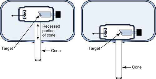
27. What are the differences between a long cone and short cone? When is each one used? What is a recessed or built-in long cone, and what are its advantages ?
Until approximately the 1970s, two types of x-ray cones were available, long and short cones. The short cone was used with the bisecting angle technique. With this technique, there is no aiming device, so that one has to “eyeball” the position of the tube in all dimensions. Obtaining the precise vertical angulation is difficult for most operators. Because it is easier to eyeball something over a shorter rather than a longer distance, a short cone was used.
When using beam-indicating devices, and eyeballing is not necessary, the lead-lined long cone is preferred. The long cone technique has two primary benefits. It reduces patient dose by reducing the field size and also increases the target-film distance, thereby reducing magnification. Because of the advantages of the long cone, it is always desirable to use it, even for the bisecting angle technique. This became feasible when Dr. Albert Richards invented the recessed or built-in long cone in the mid-1960s. The recessed cone has the advantage of a short-appearing cone, thus making it easier for the operator to execute the bisecting angle technique successfully, but with the benefits of the long cone. The recessed long cone takes up less space, which may be important in cramped quarters. The principle of the recessed cone is schematically illustrated in Figure 5-4.
28. Concerns about the effects of radiation on children has led to the establishment of a campaign to increase awareness about the dangers. Name that campaign.
This campaign is Image Gently (http://www.pedrad.org/associations/5364/ig/), an initiative of the Society for Pediatric Radiology. It has a number of signatories, including the American Academy of Oral and Maxillofacial Radiology. The campaign strives to reduce the number of radiation exposures. On its website, clinicians can download suggested protocols that list technical parameters (exposure factors) that, if followed, reduce patient dose. Although not as great a concern as radiation to children, the exposure of adults should also be minimized. The American College of Radiology and Radiological Society of North America formed the Joint Task Force on Adult Radiation Protection, known as Image Wisely (http://www.imagewisely.org) to raise awareness about this issue.
29. How has the use of occlusal radiography changed in recent years?
Occlusal images are used, among other reasons, to determine the buccolingual position of an impacted tooth, demonstrate the buccolingual dimensions of a lesion and the buccal and lingual cortices in the mandible, visualize the intermaxillary suture, demonstrate arch form, and replace periapical films in young children. An occlusal image also may be used when one wishes to visualize on one film a lesion that is too large to fit on a single periapical film, such as a large nasopalatine duct cyst.
The use of occlusal imaging has declined markedly in recent years for two reasons. The first is related to digital radiography. With the introduction of digital radiography, occlusal-size sensors are not as readily available. Because of their prohibitive cost, no rigid detectors (CCD and CMOS sensors) come in an occlusal size. Very few manufacturers of storage phosphor plates make occlusal-size plates, so unless one uses storage phosphor plates from a manufacturer that makes them, one is not likely to use them. The second reason for the drop in occlusal radiography is the advent of CBCT. The dose from CBCT is relatively low compared to medical CT (but higher than from a single occlusal exposure), so CBCT has become widely used to provide information that would otherwise have been acquired from an occlusal image.
30. What operator error results in a foreshortened image?
Foreshortening results when the vertical angulation of the tube is too great; that is, the tube is angled too steeply. Elongation, by contrast, results from a vertical angle that is too shallow. A good way to remember cause and effect is to think of the sun and your shadow. Your shadow is shortest at noon when the sun is highest in the sky (a steep vertical angle) and longest in the late afternoon when the sun is low in the sky (a shallow vertical angle).
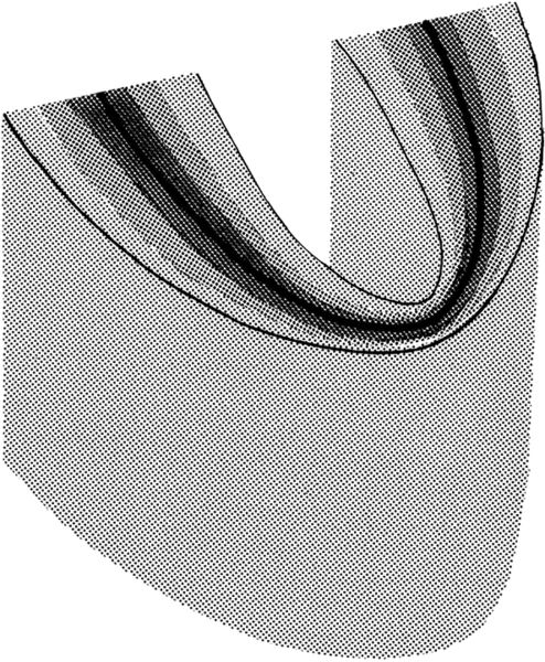
31. On a panoramic image, some structures may be clearly visible while others are not or appear blurry or out of focus. Why is this?
For structures to be visible on a panoramic image, they must be in what is termed the focal trough. The focal trough determines the distance between the nearest and farthest objects that appear acceptably sharp in the image. The width of the focal trough in different machines varies in different parts of the jaw. It is widest in the posterior region and narrowest in the anterior. For structures to appear clearly on a panoramic image, the structures must be in the focal trough. Structures that are perfectly positioned in the focal trough will show up sharpest. As structures move farther away from the focal trough, they become blurrier, until they are no longer visible. Think of the focal trough as akin to the depth of field in photography. The manner in which the focal trough and depth of field are determined is not related, but conceptually they are similar (Fig. 5-5).
32. Which radiographic view is considered the primary view for evaluating the alveolar bone for periodontal disease?
The bitewing view is the primary view for evaluating radiographic changes consistent with periodontal disease, which include loss of crestal cortication, changes in the contour of the interdental bone, horizontal and angular bone loss, and furcation involvement. The bitewing film is superior to a periapical film because distortion, including elongation or foreshortening, is slight. The reason is that the vertical angle is small (approximately plus 5 to 10 degrees), and the central ray is directed at right angles to the film.
33. Is there a generally accepted protocol for the frequency of radiographic evaluation in adult dental patients?
Yes. The U.S. Food and Drug Administration (FDA), in cooperation with the American Dental Association and other major organizations, has developed and disseminated protocols for exposing dental patients to x-ray examinations. These protocols require a history and clinical examination before prescribing an individualized radiographic examination. For more information, go to http://www.fda.gov/Radiation-EmittingProducts/RadiationEmittingProductsandProcedures/MedicalImaging/MedicalX-Rays/ucm116504.htm.
34. How should radiographic protocols be altered for pregnant dental patients?
With the use of standard radiation protection, there should be no additional risk to the fetus from x-ray exposures commonly used in dentistry. However, because of the concerns many women have during pregnancy, it is advisable to limit x-ray exposures to the necessary minimum.
35. Describe the use of CBCT in dentistry with regard to implants, endodontics, orthodontics, and impacted teeth, especially third molars.
Implants. The use of CBCT in implant planning is well accepted and widely practiced. If there is any disagreement, it is whether CBCT should be used in all cases. This is still an open question.
Endodontics. CBCT is being increasingly used in endodontic therapy. This is especially true for teeth that are being retreated after failing or failed endodontic therapy. It is also used for cases in which additional canals are suspected but cannot be found clinically, and for teeth that have unusual anatomy (e.g., a dens in dente, dilated odontome) that complicates diagnosis and/or treatment. CBCT should not be used routinely in all endodontic cases. CBCT is also indicated in cases of suspected tooth fracture.
Orthodontics. The use of CBCT in the discipline of orthodontics is one of the most unsettled and contentious issues concerning this modality. Although CBCT is used by private practitioners and some educational institutions in all orthodontic cases, many, probably most, dentists are opposed to its routine use or at least have serious reservations about it. This is based on the young age of most orthodontic patients and the lack of evidence showing that the routine use of CBCT affects the outcome. There are some situations in which there is almost complete unanimity, so the use of CBCT is appropriate. These include localizing impacted, unerupted, or supernumerary teeth, cleft palate patients, and patients for whom orthognathic surgery is a consideration.
Impacted teeth. Aside from orthodontic cases, CBCT is sometimes used to locate impacted teeth, usually mandibular third molars, to assess their proximity to vital structures. CBCT should not be routinely used in such cases. Although there are as yet no guidelines for when CBCT should be used in these circumstances, the signs seen on the panoramic image should serve as a starting point.
36. What is the buccal object rule? What do you need to apply it? How is it applied?
The buccal object rule (the SLOB rule—same lingual, opposite buccal) is a method for determining the relative location of objects that cannot be directly visualized. Examples include the location of an impacted tooth or additional root or canal. To apply the rule, one needs a reference object and two images taken at different angles.
The rule is applied as follows. In tube position 1, the images of the three objects are as depicted in Figure 5-6
Stay updated, free dental videos. Join our Telegram channel
VIDEdental - Online dental courses


