This article provides the reader with the knowledge and skills of identification and diagnostic interpretative skills using planar images, tomographic images, CBCT, MDCT, pertinent MR images, as well as bone scans and PET images. The goal is to provide sufficient in-depth knowledge of the technique, anatomy, and radiographic identifiers for the diagnosis of local and systemic pathoses. The information will train the reader to be an advocate of selection criteria as well as a follower of the “Image Gently” campaign and philosophy supported by the organized dentistry in the United States, especially in Diagnostic Radiology.
Key points
- •
Digital radiography has led to decreased radiation dose to patients.
- •
Charge coupled devices/complementary metal oxide semiconductors and photostimulable phosphors systems are currently being used as detectors for digital imaging.
- •
Although computed tomographic (CT) scanners were used for maxillofacial bone imaging in the 1980s and 1990s, the introduction of cone beam CT (CBCT) in the new millennium revolutionized the use of CT for dental and maxillofacial diagnostics. This has become a modality of choice for all implant-related diagnosis and treatment planning in dentistry.
- •
MRI is being used for diagnosis of maxillofacial conditions with soft tissue involvement as well as temporomandibular joint–related abnormalities.
- •
PET, PET/CT, PET/MRI, or PET/CBCT fusion techniques are on the rise for the detection of occult pathoses within jaws as well as diagnosis of osteonecrosis of the jaw.
Introduction
Imaging is an integral part of the Oral and Maxillofacial diagnostics. Before the beginning of any imaging protocol, the health care provider must ask the question, “Where does the imaging fit in within the diagnostic sequence?” In other words, “Do I need the image?” Once the above question has been properly answered, then the next logical question should be, “What type of images should I get?” The choice of image should be the one that is least invasive and most diagnostic. It is often a compromise between the dose and the optimal resolution, if it is a radiation-based image. Other images are selected based on their diagnostic efficacy.
Why to Image
Imaging is a universal diagnostic tool. In many cases, images uncover the underlying cause of symptoms and form a basis for scientific investigation. Images support the evidence-based case management. Frequently, images document the presence or absence of disease, leading to further investigations that are histologic, immunologic, molecular, or genetic in nature. Finally, images are used for identification of normal anatomic variations so that unnecessary treatment can be avoided.
When to Image
All radiographs are prescribed after a careful clinical examination. They are prescribed only when the clinician anticipates additional diagnostic details from the image. Radiographs are required when the imaging forms a basis for further intervention and follow-up. Last, images are needed because they are the standard of care and necessary to treat the patient.
Where to Image
Isolation of the correct anatomic area as a “suspect” is important. If the pain is from an occult source, then broad-based imaging is called for. The type of trauma or disease suspicion dictates the type of imaging in most cases. Additional indications in dentistry exist, for instance, before implant bone assessment.
How to Image
The details of imaging are largely left to the radiologist and the technical staff. The decision to go digital is dictated by the availability of the imaging technology at the facility. Clinicians’ input in the selection of slice thickness or the viewing angles is extremely important. Examinations with or without contrast or a combination should be identified and requested before the examination. Cine-loop of video recording for magnetic resonance (MR) studies and 3-dimensional (3D) reconstruction for computed tomographic (CT) studies can be requested before the images are acquired.
Although planar radiographs, both film and digital, have become obsolete by the advent of 3D imaging in medicine, planar images continue to be of value, in oral and maxillofacial radiology. Intraoral periapical radiographs and bitewing radiographs continue to be gold standards for assessment of many conditions, especially dental caries and crestal bone loss. 3D imaging has become a necessity for preimplant evaluation of jaws and the diagnosis of pathologic abnormality within the maxillofacial region that was not previously possible with planar radiographs alone.
Imaging technique and normal anatomy
Intraoral Radiography
Imaging protocols
The paralleling technique is used for geometric accuracy of the images, and a rectangular collimator is used for reducing patient dose as well as increasing the contrast within the image. Intraoral positioning devices are used for achieving the parallelism and stability before any exposure.
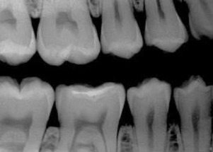
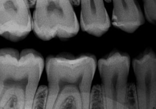
Voltage is the potential difference between 2 electrical charges. Within a radiograph tube head, the voltage is measured between the negative cathode and positive anode. Voltage determines the speed of electrons from cathode to anode. When the voltage is increased, the speed of electrons is increased, resulting in the elections striking the target with greater force, resulting in a radiograph beam with a shorter wavelength. Voltage is measured in volts or kilovolts (1 kV = 1000 V). A polychromatic beam is the result of varying kilovoltage in an alternating current (AC) tube. Density and contrast are the 2 most important parameters resulting from radiograph exposure. Density is the overall degree of darkness or blackness of a film or image. If all other factors remain constant, an increase in kilovoltage results in increased density, and a decrease in kilovoltage results in decreased density. Image or film contrast refers to how sharply dark and light areas are differentiated. Radiographic contrast is the combination of subject contrast and film contrast (analog detector). In a digital detector, other factors come into play (like the bit depth), but the kilovoltage peak (kVp) will be the key factor. An adjustment in kilovoltage peak results in a change in the contrast of a dental radiograph. When low kilovoltage settings are used (<70 kVp), a high contrast image will result ( Fig. 1 ). An image with high contrast is useful in the detection of caries. When high kilovoltage settings are used (>80 kVp), low contrast results with many shades of gray. An image with low contrast is useful in the detection of periodontal and periapical disease ( Fig. 2 ). A compromise between high and low contrasts is highly desirable.
Radiographic exposure parameters are typically between 60 and 70 kV and 5 and 8 mA using direct current (DC) radiographic machines. The AC radiographic machines are no longer recommended for use with the digital sensors.
Table 1 shows the factors that affect the image quality and the resultant variation in image density and contrast. Table 2 shows the variation in image magnification and sharpness due to variation in geometric factors used to acquire the radiographic image.
| Factor | Change | Radiographic Density | Radiographic Contrast |
|---|---|---|---|
| kV | Increase >80 | Increased (darker) | Low contrast |
| Decrease 60–70 | Decreased (lighter) | High contrast | |
| mA | Increase | Increased (darker) | No effect |
| Decrease | Decreased (lighter) | No effect | |
| Exposure time | Increase | Increased (darker) | No effect |
| Decrease | Decreased (lighter) | No effect | |
| Filter thickness | Increase (thick) | Decreased | Decreased |
| Decrease (thin) | Increased | Increased | |
| Object density | Increase | Decreased | Varies |
| Decrease | Increased | Varies | |
| Ambient light | Increase | No effect | Decreased |
| Decrease | No effect | Increased | |
| Glare | Increase | Decreased | No effect |
| Decrease | Increased | No effect | |
| Collimator size | Increase | No effect | Decreased |
| decrease | No effect | Increased | |
| Target-detector distance | Increase | Decreased | No effect |
| Decrease | Increased | No effect |
| Geometric Factor | Change | Image Magnification | Image Sharpness |
|---|---|---|---|
| Collimator size | Increase | No effect | Decreased |
| Decrease | No effect | Increased | |
| Object-detector distance | Increase | Increased | Decreased |
| Decrease | Decreased | Increased | |
| Target-object distance | Increase | Decreased | Increased |
| Decrease | Increased | Decreased | |
| Focal spot size | Increase | No effect | Decreased |
| Decrease | No effect | Increased |
In intraoral digital radiography, the resolution of an image is limited by the thickness of the layer, not pixel size. Resolution is measured by line pairs resolved per millimeter (lp/mm) and is also limited by what the human eye can detect. Typically, film resolution is greater than 20 lp/mm; the intraoral photostimulable phosphors (PSP) detector resolution is between 7 and 14 lp/mm, and the charge coupled devices/complementary metal oxide semiconductors (CCD/CMOS) sensor resolution is between 10 and 24 lp/mm. Digital imaging systems are capable of capturing up to 256 different densities, whereas the monitors may or may not even display all of the densities captured in one screen. If the resolution of the monitor is higher than the captured densities, then there will not be an issue displaying those images. However, the human eye can only distinguish 32 or so different densities, which is a limiting factor in the diagnostic process. The ideal sensor (detector) should be able to display a full range of densities in order to have wider latitude. Although the dynamic range of film extends to 4 orders of magnitude with hot lighting, the CCD/CMOS sensors extend to 2 orders and PSP sensors extend to 5 orders of magnitude of radiograph exposure. The detector sensitivity is the ability to respond to small amounts of radiation. In intraoral film-based radiography, the sensitivity is directly related to the film speed. The sensitivity of the digital sensors is affected by pixel size and system noise. Although PSP systems allow dose reductions close to 50% compared with F-speed film, the CCD/CMOS sensors have a lesser dose reduction than PSP systems. Modulation transfer factor (MTF) is a measure of the combined sharpness and resolution factors. Generally, the MTF of fast films is superior to the MTF of PSP at high spatial frequencies, which explains the sharpness and higher resolution of E- or F-speed films compared with PSP plates. In terms of contrast, the displayed image provides up to 8 times the amount of information that the human eye can actually resolve.
The greatest perceptual sensitivity is about 5 lp/cm (1-mm-wide pixel). It is interesting to note that the sensors can display more than 2.5 times the amount of information that the human eye can actually perceive.
Studies have looked at both natural and simulated carious lesions and tested the resolving power of film and digital intraoral detectors. The conclusion is that the ability to recognize incipient dental caries lesions is not dependent on image receptor (film or digital), the system used, or the manner in which it is displayed. The most important part of lesion diagnosis is knowledge base, training, and to a lesser extent, all other factors, including detector resolution, exposure factors, and display systems.
The kilovoltage peak rule
It is generally recommended that when the kilovoltage peak (for AC machines) is increased by 15, exposure time should be decreased by half when the milliampere is fixed or cannot be altered. When the kilovoltage peak is decreased by 15, exposure time should be doubled. When kilovoltage peak is increased, it results in increased density and hence lower contrast. When the kVp is decreased, it results in lighter density and hence higher contrast, which is recommended for all dental radiographic examinations. When the kilovoltage peak is increased, the milliampere seconds must be decreased in order to maintain the previous radiographic density.
Radiographic images are either stored within a practice management software independently or in a picture archiving and communication system that is connected to a practice management software. This metnod of storage is especially true when the volume of the radiographic data is high and needs networking for large group practice situations, hospital, or a dental school environment. The stand-along dental practices may simply depend on their native practice management software to accomplish this job.
Imaging findings and pathology
Due to the fact that the anatomic resolution of the digital intraoral periapical radiographs are more than 20 line pairs/mm, the intraoral radiographs are highly recommended for visualization of periapical bone changes or changes related to the tooth. Bitewing radiographs are still the gold standard for the detection of incipient dental caries because most cavitated lesions cannot be observed clinically, which makes the radiograph the only objective source of detection. In a study by Sansare and colleagues, it was noted that the radiographic shallow carious lesions were often cavitated. Occlusal radiographs are recommended for visualization of areas that are not covered by periapical radiographs alone, but due to the fact that size 4 digital CCD or CMOS sensors are not available, the technique has become somewhat obsolete. For localization of pathoses within the jaws, a limited volume cone beam CT (CBCT) is recommended instead.
Diagnostic criteria
The periapical, bitewing, and occlusal radiographs have to be technically accurate without any distortions, digital processing errors, motion artifacts, or any other positioning or exposure errors that make the radiographic image less than ideal to interpret.
Differential diagnosis
The periapical radiographs are frequently used in dental practice for differential diagnosis of apical lesions that result in either demineralization of bone or scleroses of bone. Odontogenic lesions are typically in close association with the offending tooth or teeth. Nonodontogenic lesions could be either in the close vicinity of the teeth or entirely away from the teeth within the jaws. The determination can be made via further investigation or additional imaging modalities. This diagnosis is paramount because the involvement of the tooth in the treatment plan depends on the determination of the odontogenic nature of the lesion.
Pearls, pitfalls, and variations
Intraoral radiographs, although the most frequently used type of radiographs in general dental practices, due to the nature of their 2-dimensionality, cannot be used for the evaluation of bone before implants or to evaluate implants after they are placed, because the third dimension is missing from the radiographs. Intraoral radiographs cannot be used to evaluate bony pathologic abnormality that has spread beyond the apex because the 2-dimensional (2D) radiographs may not show the lesion entirely.
Anatomic variations are numerous and often encountered in radiographic diagnosis. Variation and deviation from normal anatomy are both part of a good differential diagnosis.
-
Intraoral radiographs are the most frequently used radiographs for the diagnosis of odontogenic pathologic abnormality in a dental office.
-
DC radiograph machines have replaced the AC radiograph machines, especially when digital sensors are used.
-
Bitewing radiographs are still considered a gold standard for the diagnosis of interproximal incipient caries.
-
Significant radiation dose reduction can be achieved using digital sensors provided the errors and re-exposures are kept to a minimum.
What the referring dentist needs to know
Because intraoral radiographs are taken in every dental office, unless there is a pathologic finding that is noted beyond the competence of a general dentist, most intraoral radiographs should be interpreted by the general dentist, and the findings need to be recorded in the electronic dental record. The radiographs can be sent for additional interpretation to an oral and maxillofacial radiologist (OMR) when needed, and advanced imaging can be recommended when the clinical situation demands such a need. The advanced radiographic modality is obtained in conjunction with an OMR and is recommended that those images/DICOM volumes be interpreted by such a specialist.
Summary and Conclusions
Intraoral radiographs, both film and digital, are obtained within a dental office. In some states in the United States, they are done exclusively in an imaging center under the guidance of a licensed dentist. In most situations, they are interpreted chair-side by the dentist. The radiographs are obtained via digital sensors, CCD, CMOS, or PSP, using DC radiograph machines, and they are integrated into the practice management software or an electronic dental record.
Extraoral Imaging
-
Extraoral skull views (plain films and direct digital images)
-
Tomography (linear and multidirectional) (outdated)
-
Panoramic imaging, screen/film or digital
-
CT
-
CBCT
-
MRI
-
PET
-
PET/CT, PET/CBCT, and PET/MR fusion techniques
-
Scintigraphy
-
Sialography and CT sialography
-
Sialendoscopy
Skull Radiographs
Skull radiography declined with the introduction of CT. The NICE (National Institute for Health and Care Excellence) guidelines do not recommend the use of planar view radiography in the assessment of head injuries. The recommendations from the Royal College of Radiologists (2013) state that plain film/digital skull radiograph images may be used in trauma for triage purposes when CT is unavailable.
-
Lateral cephalograms: nasal bones, frontal sinus, and sphenoid sinus
-
Submentovertex (SMV): zygomatic arch and sphenoid sinus
-
Waters view: maxillary sinus, frontal sinus, nasal septum, mastoid air cells, zygomatic bone, odontoid process of C2
-
Posteroanterior (PA) cephalogram: orbit, nasal cavity, and frontal sinus
-
Reverse Towne: condyles (head and neck)
-
Lateral oblique body: mandibular body
-
Lateral oblique ramus: ramus including condyle and coronoid process
-
Panoramic: mandibular body and ramus, maxilla, upper and lower teeth, glenoid fossa, zygomatic arch, and process
Imaging protocols
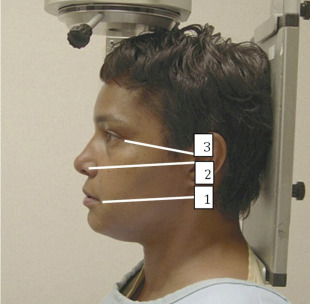
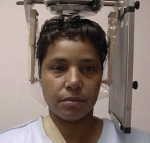
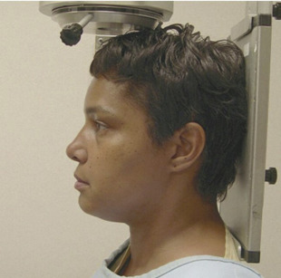
The 3 most important planes are depicted in Fig. 3 . These planes are useful for appropriate positioning of the patient within a cephalostat for skull views.
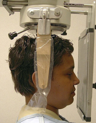
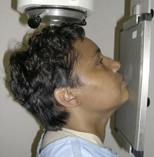
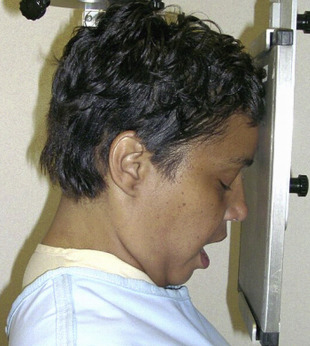
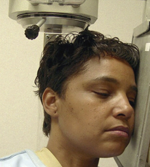
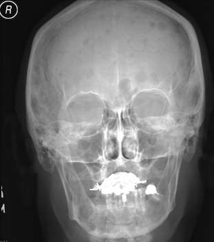
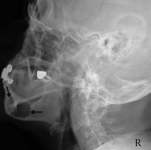
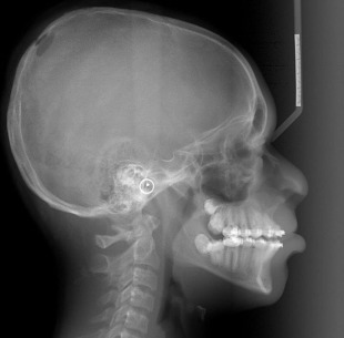
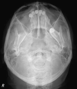
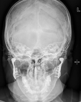
The canthomeatal (C-M) line is kept perpendicular to the image receptor for acquisition of the PA skull image ( Fig. 4 ), whereas for the PA cephalogram, the C-M line forms a 10° angle with the horizontal plane, and the Frankfurt plane is perpendicular to the image receptor. In the lateral skull or lateral cephalogram ( Fig. 5 ) acquisition, the detector is kept parallel to the midsagittal plane. The beam is perpendicular to the detector. For the acquisition of Waters view, the C-M line is adjusted so that it is at 37° with the detector and the beam is perpendicular to the detector ( Fig. 6 ). For the Reverse Towne view, the C-M line is adjusted so that it is −30° with the detector ( Fig. 7 ). The beam is still perpendicular to the detector. For the lateral oblique body, the detector is in contact with the cheek at the molar area, and the radiograph beam is aimed at the premolar-molar area. For the lateral ramus projection, the detector is in contact with the cheek at the ramus area and the radiograph beam is aimed at the ramus area. Although rarely done, for the SMV projection, the C-M line is kept parallel to the detector, and the beam is projected perpendicular to the detector. For detection of maxillary pathoses and skull vault superiorly, an anteroposterior (AP) skull image is preferred (see Fig. 9 ), wherein the C-M line is kept perpendicular to the detector, and the beam is parallel to the C-M plane (see Figs. 3–7 ; Figs. 8 and 9 ).
Imaging findings and pathology
Planar images still have diagnostic value, although they are infrequently obtained in medical centers and hospitals. Demonstration of disseminated systemic skeletal disease like that seen in Fig. 10 is a great example. The PA radiograph in this figure shows the characteristic punched out lesions of multiple myeloma. The petrous ridge is superimposed over the lower third of the orbital area. The technique is used to assess the orbital borders, the vertex of cranial vault, the inferior border of occiput, and the lateral margins of the cranial vault ( Figs. 11–14 ).
Pathologic abnormality detected on skull views
Although infrequently used for the detection of skull pathologic abnormality other than sinus afflictions, skull views are useful and are often the first views to assess the maxillofacial pathoses, used for ruling out trauma and also for selection of the advanced imaging based on the planar imaging. Lateral oblique views were used with 5 × 7 cassettes to image the mandible and TMJ area of one side. Two lateral oblique views were needed to image both sides of the mandible and TMJ areas. They became outdated after the introduction of panoramic radiography. The skull views are used for overall detection of gross pathoses, to assess symmetry, and to rule out fractures of facial skeleton.
Skull trauma on planar radiographs
Linear skull fractures, the most common form of fractures, involve a break in the bone but no displacement. These fractures are detected on lateral skull views. Depressed skull fractures may be noted on both lateral skull views and SMV views. Depressed skull fractures can be potentially nonaccidental and should be viewed with caution. Diastatic fractures occur along suture lines and are usually noted in newborns and infants in whom fusion of the sutures is not completed yet. In this type of fracture, the normal suture lines are widened. Basilar skull fractures are the most serious and involve a linear break in the bone at the base of the skull. Most basilar fractures occur at 2 primary locations, the temporal region and the occipital condylar region, which leads to dural tears and cerebrospinal fluid leak. The ping-pong fractures are noted in children who fall and injure their skulls against a hard blunt object. It is important to differentiate between normal sutures that are winding, serpiginous lines less than 2 mm in width, have the same width throughout, and do not run a straight line. It is also important to note that about 15% of patients with skull fractures sustain concomitant injury to the cervical spine. Therefore, evaluation of the skull without evaluation of the cervical spine has both clinical and medicolegal implications.
Stay updated, free dental videos. Join our Telegram channel
VIDEdental - Online dental courses


