Fig. 3.1.
This ED 10 G6 implant lacks bone apposition down to below the threaded pin. At the time the picture was taken, the implant had been in situ for 5 years. The load-transmitting segments are in full function. The implant is located in too high a position (low G value). Particularly at the anterior aspect, it almost falls short of the white line of maximum load transmission, indicating that the implant is unlikely to survive in the longer term. This example clearly demonstrates the interaction between bacterial attacks and the functional tendency to preserve peri-implant mineralization. In this specific patient, the conditions for bacterial attack were particularly favourable, due to very poor oral hygiene, rough vertical implant surfaces, elasticity of the implant-restoration complex, and heavy smoking
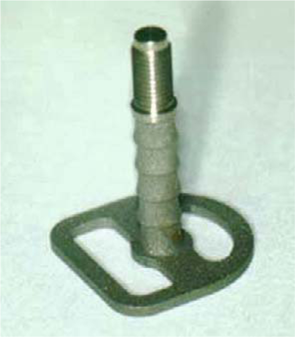
Fig. 3.2.
The transition from “disk implants” to BOI implants was marked by a period in which implants with dual load transmission were the state of the art. In this design, load transmission was supposed to take place both in the vertical and in the basal implant part. These implants are perfectly serviceable if the behaviour of both the vertical and the horizontal bone structures used for anchorage are mechanically synchronized with the implant surface. This is mainly the case in the anterior segment of the mandible. The ribs are 1.5 mm apart and represent the G graduation
Attempts to achieve optimal integration of the vertical implant segment by combining macroscopic steps and microscopic surface enlargement by sandblasting have led to better clinical results in terms of initial healing. Permanent osseointegration can even be obtained along the vertical implant segment, provided that the number of implants placed in each arch is adequate and that the design of the bone-implant-restoration complex is sufficiently rigid. Counteracting forces include elastically intruding occlusal forces, functional shearing loads, unbalanced extrusion forces, and flexion of the jaw at large. The latter may amount to several millimetres and can be readily measured, especially in the mandible. These counteracting forces lead to mobility at the implant-bone interface, thereby jeopardizing the close osseointegration of long threaded pins. In the presence of surface-enlarged threaded pins elastic micro-movement (Ashman and van Bushkirk 1987) may irritate the connective tissue structures and, at the same time, support inoculation of the bacteria residing on the roughened surfaces. Any infections in the wake of bone avulsion that are capable of advancing to the deeper bone segments will result in crater-style osteolysis. While collapses of this type do not necessarily impair the function of the implant (Fig. 3.1) as long as the force-transmitting disks (notably the basal disk) remain intact, they are nevertheless undesirable. Roughened implant surfaces close to the oral cavity involve a greater risk of bacterial retention. Moreover, resilient implant-restoration systems seem to result in mechanical irritation by mobilizing the surfaces of the threaded pin and the bone against each other. Such irritation is also likely to reduce the chances of reintegration should the implant become mobile itself.
The tendency to reduce the number of implants for bridge restorations originally arose from cost considerations and considering biomechanics. In accordance with that tendency, the transition from the first disk implants to true BOI designs was gradually made. After all, the bridge spans and the associated positional changes between abutments increased as the number of implanted abutments decreased. In other words, the mutual mobility of the abutments became greater, which was not per se inconsistent with good stability by basal osseointegration. The threaded pins were subjected to a higher degree of deflection, which caused the implants to intrude deeper into the bone and mucosa creating friction. The hard-tissue irritation associated with the intra-bony movements involved a risk of vertical bone loss along the threaded pin. When BOI implants with a smooth shaft were introduced, the threaded pin will recede into the associated hard- and soft-tissue structures without causing any noticeable irritation or bacterial inoculation. Ultimately, this structural detail prepared the ground for comprehensive implant therapy along the maxillary sinus, where the therapeutic spectrum had hitherto been limited. Furthermore, large distances between the threaded pins made it unlikely for the peri-implant bone to behave mechanically in synchronization with the threaded pin. Such behaviour would have been required if osseointegration of vertical implant segments needed to be maintained. The function of the vertical implant segments has since been largely reduced to compensating for motional differences between the integrated disk areas, since these would never quite behave synchronously. The bridge itself became the fixed reference point within the masticatory system; however, unlike with crestal implants and teeth, the pontics of BOI-based bridges (especially in strategic positions and with few basal plates) are no longer directly connected with the fate of the alveolar bone.
To summarize: the direction that has eventually led to genuine BOI systems was initially defined by Scortecci’s implant designs featuring depth markers and surface-enlarged shafts. The literature and thinking associated with crestal implantology used to be so persuasive that all designs for enossal implant segments would feature micro- and macromechanical surface enlargement for a long time. More recently, hybrid designs were developed in which the shaft segments near the mucosa were smooth and the basal segments were roughened for surface enlargement. These were the first designs to offer true basal osseointegration and strategic abutment positioning, using only four implants per jaw.
As will be demonstrated elsewhere in this book, overgrowth of subcrestal implant segments by connective tissue does not irreversibly prevent osseoadaptation. By contrast, subsequent osseoadaptation or osseointegration is no longer a realistic expectation once bacterial infection has spread to an osteolytic area, which is presumably due to the associated granulation around the implant.
With the smooth-shafted designs available today, implant treatment along the maxillary sinus can be readily performed by placing the disk and part of the threaded pin inside the sinus. Trans-sinus implant placement becomes unavoidable if the vertical bone volume caudally to the sinus is small and the expected changes in the intra-bony trajectories are also small. In this situation, intrasinus implantation is a better biomechanical option. The use of crestal implants would involve adjuvant procedures for sinus floor augmentation to facilitate load transmission along the entire vertical portion of these implants.
3.2 Load Transmission by Disks or Rings
The crestal and the basal plate of multi-disk elastic implants used for basally osseointegrated implant-restoration systems have different functions. The main purpose of the crestal plate is to provide additional stabilization of the implant. The crestal plate loses its importance once the basal plate has ossified to full load-bearing capacity. Since the crestal and basal plates of the former “disk implants” were equally resilient against the threaded pin, an estimated 10-15% of these cases had to be followed up by subsequently removing the crestal plate. Unless this was done soon, there was a risk of infection and osteolysis advancing from crestal direction. Once the infection was impacted in the submucosal or intraosseous area, there was a risk that it would eventually advance to the basal plate, so that the entire implant was eventually lost.
One of the most useful developments of the past few years has been to improve the resilience of the crestal plate in relationship to the basal disk. In new BOI implants, the web bar of the crestal plate is located perpendicular to the web bars of the basal plate. In other words, this part of the crestal plate is inserted directly into the palatal bone, well protected against resorption.
The osteotomy area in the vestibular bone, by contrast, is crossed only by the ring of the crestal plate. The ring acts like a tent keeping the periosteum away from the bone, thus facilitating any primary or secondary augmentation procedures.
3.3 Distance Between Crestal and Basal Load-Transmitting Surfaces
Double/multiple disk implants have been available in France since around 1988. The disk-to-disk interval on these implants is 3 mm. Specific double cutters matching these distances for lateral osteotomy are available. We have since, in collaboration with Spahn, introduced implants and osteotomy tools for 5-mm disk-to-disk intervals in our clinic.
This modification was prompted by our observation that the room for manoeuvre inside the bone was very small whenever the need for surgical removal of crestal plate arose. This lack of space involved a high risk of intact bone being engaged or, indeed, damaged by surgical instruments. These manipulations in the area of the crestal plate have now become easier whenever the need for corrective intervention arises in cases where the newly introduced designs with the larger disk-to-disk intervals were used.
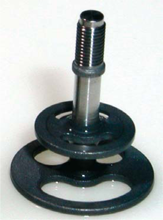
Fig. 3.3.
A configuration in which both disks having the same thickness and featuring two web bars each will result in an unequal distribution of functional loads, i.e. the crestal disk is subjected to greater forces than the basal disk. Consequently, the crestal disk will be more susceptible to overload osteolysis, in which case the basal disk will still remain osseointegrated for the time being. In fact, the greater risk of osteolysis around the crestal disk is also a function of its greater rigidity compared to a basal disk of the same thickness. Put differently, it does not even take an unbalanced force distribution to increase the risk. Some users have severed one web bar of crestal disks prior to insertion in order to make them more elastic
Fig. 3.4.
The crestal disk in today’s BOI designs includes only one web bar, which offers a greater degree of resilience at the crestal than at the basal disk. The crestal disk is inserted with the web bar facing palatally, such that the incoming forces are guided right into the palatal bone, which is protected against resorption. This is in contrast to the basal plate, where incoming forces are distributed throughout the ring in accordance with the biomechanics of the cranial bone where both the vestibular and the central bone structures are equally well protected against resorption. The picture illustrates the polished crestal segments and the small diameter of the threaded pin (< 2 mm)
There was yet another consideration that led to this modified design. For the bone surrounding the disks to be functional in terms of load transmission, an adequate blood supply has to be present. Implant structures will impede or disrupt the blood supply. This shortcoming became clear in the 1980s when the first series of “disk implants”, which featured inadequately thin microperforations in the basal plates combined with short threaded pins, were frequently lost because of poor conditions in terms of blood supply and immune defence crestally to the disks. An adequate blood supply is decisive for long-term survival of BOI, which specifically applies to the area of the crestal disk as well. Ever since we were able to insert BOI implants featuring the larger disk-to-disk intervals of 5 mm, we observed that both basal plates integrated evenly well. As will be shown in Chapter 23
Stay updated, free dental videos. Join our Telegram channel
VIDEdental - Online dental courses


