Clinical Example of an Older Patient
As discussed in Chapter III, natural characterization is simulated in the build-up. In this chapter, simulation of an opaque layer in the incisal tip, a thick translucent layer in the proximal region, dark areas, and check lines (cracks and hairline fractures) are discussed.
1. Clinical Example
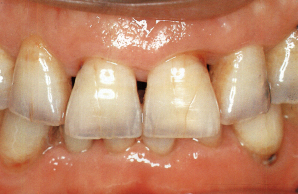
Fig. IV-1 Simulation of a thick yellow opaque layer (result of change in the fingerlike structure from attrition at the incisal tip), formation of hardened opaque dentin, a thick blue translucent layer in the proximal region, check lines and various stains commonly seen in the elderly are shown here. In addition, simulation of dark areas from transparent dentin not seen in this case will be explained as well.
2. Primer (Figs. IV-2a~d)
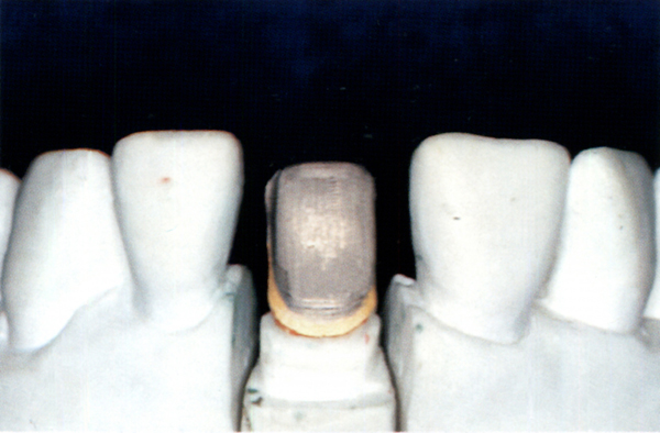
Fig. IV-2a A framework with the margin coated with gold bonding agent is ready for application of opaque porcelain.
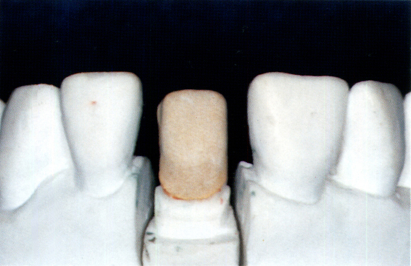
Fig. IV-2b Opaque porcelain layer built up separately as cervical and middle portions.
• Opaque porcelain: Vintage (SHOFU/UNITEC)
• Cervical portion: mixture of A4O and orange opaque (OM3) at a ratio of 3–4:1.
• Middle portion: A4O.
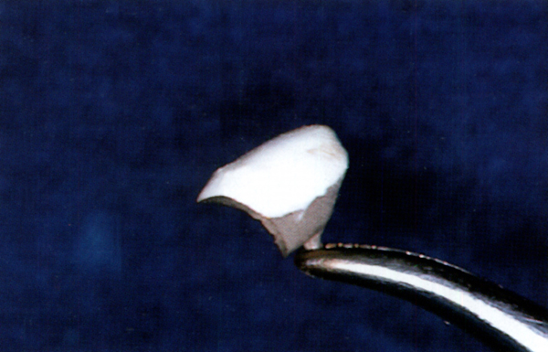
Fig. IV-2c Application of cervical-color porcelain to simulate the root portion.
• Cervical-color porcelain: Vintage; mixture of AC (cervical-color porcelain) and B4B (dentin porcelain) at a ratio of 1:1.
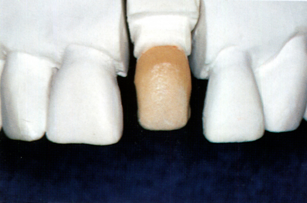
Fig. IV-2d View after firing. Note that the radicular morphology is simulated and the cervical-color porcelain is extended transitionally to the incisal portion.
3. Building Dentin Porcelain (Figs. IV-3a and b)
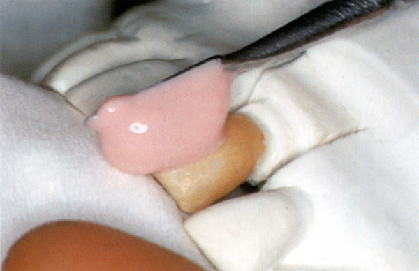
Fig. IV-3a Dentin porcelain is built up using the spatula with thorough condensation.
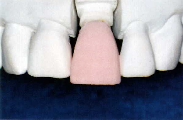
Fig. IV-3b Built-up dentin porcelain. Since dentin porcelain should be exposed at the incisal edge in a completed crown to simulate attrition, it is built up 1.0–1.5mm longer than the same tooth on the opposite side.
• Dentin porcelain: Vintage A4B.
4. Cut-Back of Dentin Porcelain (Figs. IV-4~IV-8)
Step 1 First cut-back
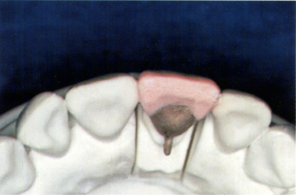
Fig. IV-4a The area to be reduced is marked on the labial surface. The mark indicates a thickness of 1.2–1.3mm at the incisal portion to simulate very high translucency.
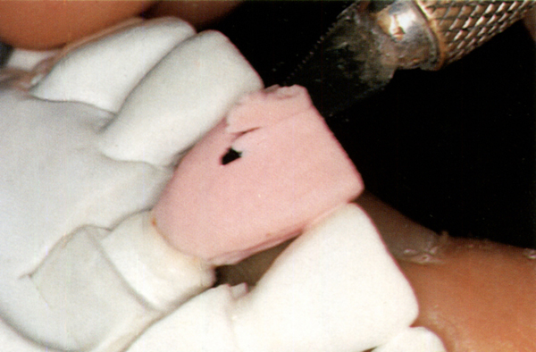
Fig. IV-4b Labial reduction. To simulate general translucency, the reduction is made relatively flat over the entire labial surface corresponding to the cemento-enamel junction by using the marked lines as reference.
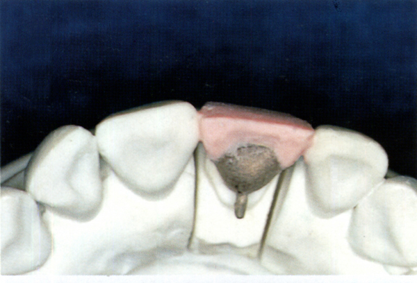
Fig. IV-4c Incisal view after labial cut-back.
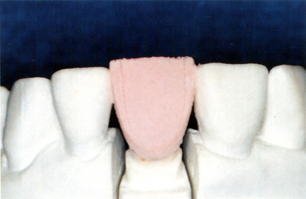
Fig. IV-4d Labial view; marking proximal cut-back lines. These lines are marked on the reduced labial surface approximately 1 mm from the proximal surface and gradually narrow cervically.
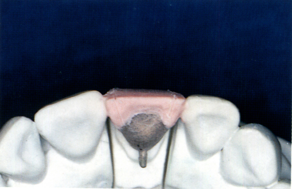
Fig. IV-4e Incisal view; mark the proximal cut-back lines.
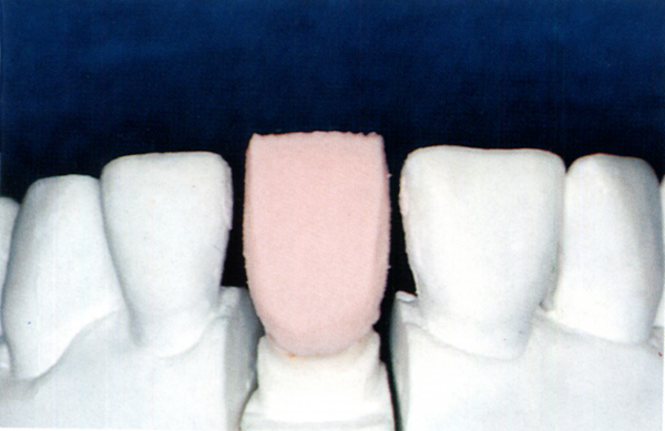
Fig. IV-4f Labial view; contour of dentin porcelain after the first cut-back.
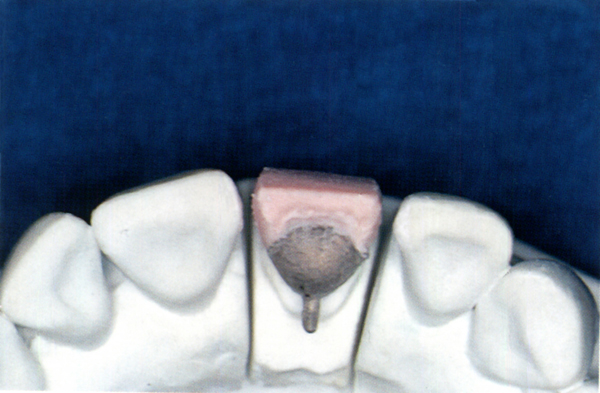
Fig. IV-4g Incisal view. Note that the dentin porcelain is purposely narrowed lingually to simulate the complete wraparound effect.
Step 2 Second cut-back
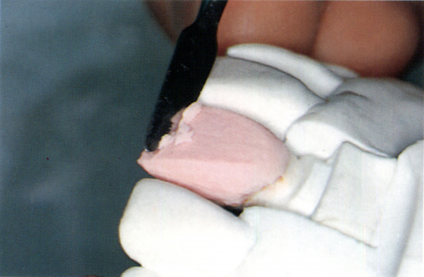
Fig. IV-5a With a LeCron carver, the dentin porcelain is cut flat at the incisal third starting from the first cut-back incisal line and extending to the opaque porcelain layer so that it is located at the labiolingual center in the dentin.
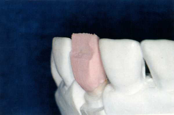
Fig. IV-5b Lateral view after the second cut-back.
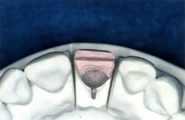
Fig. IV-5c Incisal view; reduction is made at the labiolingual center.
Step 3 Simulation of stained opaque layer
Stay updated, free dental videos. Join our Telegram channel

VIDEdental - Online dental courses


