Introduction
Our objective was to evaluate the factors that affect effective torque control during en-masse anterior retraction by using intrusion overlay archwire and partially osseointegrated C-implants as the exclusive sources of anchorage without posterior bonded or banded attachments.
Methods
Base models were constructed from a dental study model. No brackets or bands were placed on the posterior maxillary dentition during retraction. Different heights of the anterior retraction hooks to the working segment archwire and different intrusion forces with an overlay archwire placed in the 0.8-mm diameter hole of the C-implant were applied to generate torque on the anterior segment of the teeth. The amount of tooth displacement after finite element analysis was exaggerated 70 times and compared with tooth axis graphs of the central and lateral incisors and the canine.
Results
The height of the anterior retraction hook and the amount of intrusion force had a combined effect on the labial crown torque applied to the incisors during en-masse retraction. The difference of anterior retraction hook length highly affected the torque control and also induced a tendency for canine extrusion.
Conclusions
Three-dimensional en-masse retraction of the anterior teeth as an independent segment can be accomplished by using partially osseointegrated C-implants as the only source of anchorage, an intrusion overlay archwire, and a retraction hook (biocreative therapy type II technique).
In biocreative therapy (C-therapy), torque control requires special consideration, since one is retracting the anterior teeth in a segment unattached to the posterior teeth. This concept was developed because partially osseointegrated mini-implants or plates can easily endure multi-directional heavy forces even when they support orthodontic archwires. In C-therapy, it is possible to retract the anterior segment independently by directly placing the wire into the hole of the mini-implant. When retracting against dental anchorage, or against indirect miniscrew anchorage, actual intrusion vectors on the anterior teeth are hard to achieve without unwanted reactive forces affecting the posterior dental units. With the biocreative approach, true intrusion vectors without side effects are possible, since the osseointegrated C-implant or the C-plate is secure against rotational moments. The posterior teeth can be left intact. We reported previous finite element analysis (FEA) studies using the biocreative therapy type I technique, demonstrating 3-dimensional (3D) anterior retraction with gable bends and an anterior retraction hook (ARH). For patients with a deepbite tendency in the anterior segment, we have addressed a weak point of the type I technique by an applying intrusion force with an overlay archwire applied to the anterior segment. We called this the biocreative therapy type II technique. This is an improved method of applying the segmented intrusion arch technique of Burstone.
Two common orthodontic biomechanical systems today are the use of a continuous archwire (eg, straight-wire appliance) and segmented archwires (Burstone’s segmented arch technique). Straight-wire appliance techniques are not technique sensitive but have limited applications for some tooth movements. Segmented archwire techniques enable more effective and accurate tooth movements by using mechanically determinate force systems by separating the anterior and posterior segments. These systems require a better understanding of the biomechanics involved. Problems of anchorage loss in segmented arch systems are resolved with temporary skeletal anchorage devices. Chung et al introduced the technique that uses minimum orthodontic hardware and minimizes side effects by replacing the posterior appliance segments with the partially osteointegrated C-implant. This beneficial protocol is only possible if the mini-implant will not loosen in response to the heavy or dynamic forces that would be necessary. The C-implant (sandblasted, large-grit, acid-etched mini-implant) will allow the application of a nickel-titanium (NiTi) reverse curve of Spee overlay archwire, which will apply a moment to the mini-implant but not loosen the screw. This intrusion overlay wire produces forces that control both the torque and the vertical position of the incisor segment ( Fig 1 ). The size of overlay NiTi archwire can be changed easily. To date, there are no studies of the factors involved in the control of anterior torque by this technique. Clinical studies and case reports have described the technique. In this study, we constructed a 3D finite element model of the maxillary teeth, periodontal ligament (PDL), and alveolar bone after extracting the first premolars. After placement of the orthodontic mini-implant with the 0.8-mm hole between the second premolar and the first molar, and 8 mm apical to the expected bracket position, we applied an intrusion force using a reverse-curved NiTi archwire from a C-implant head to the point between the central incisors to the segmented archwire of the 6 anterior teeth using the mini-implant as a posterior orthodontic tube. We simulated the effect on torque control using different heights of retraction hooks located between the lateral incisor and the canine, and different amounts of intrusion force on the NiTi overlay archwire.
Material and methods
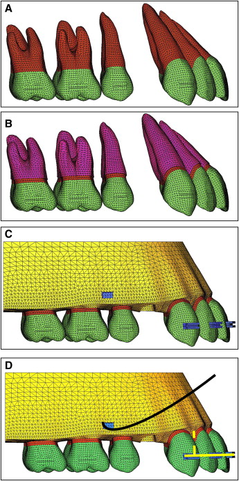
For the finite-element model, we obtained the tooth outline forms through the 3D laser scanning of a maxillary right dentition from a dental study model (base model) (model-i21D-400G, Nissin Dental Products, Kyoto, Japan) of an adult with normal occlusion. Using the micro-arch bracket (Tomy, Tokyo, Japan), we aligned and leveled using a broad arch form (Ormco, Glendora, Calif) and referred to previous studies for inclination and angulation. We did not add a curve of Spee or a curve of Wilson ( Fig 2 , A ), and the thickness of the PDL was assumed to be uniform (0.25 mm) ( Fig 2 , B ). The alveolar bone crest was constructed to follow the cementoenamel junction curvature 1 mm apical to the cementoenamel junction. The 3D finite element model included 12 teeth, a space for the missing first premolar’s periodontal space, and alveolar bone, and was bilaterally symmetrical ( Fig 2 , C ). In the base model, the distance from the incisal edge of the maxillary central incisor to the bracket slot (perpendicular to the occlusal plane) was 4.5 mm, 11 mm labial to the cementoenamel junction, and 11.8 mm to the labial alveolar crest. In the finite element model, teeth, alveolar bones, brackets, periodontal spaces, the C-implant, and the archwire were constructed with fine tetrahedron solid elements; the teeth and brackets were connected without interference, and each tooth contacted the next at the contact point as individual elements ( Fig 2 , D ). In this study, teeth, alveolar bones, and periodontal spaces were assumed to be isoparametric and homogeneous linear elastic bodies; the material properties of the elements were Young’s modulus and Poisson’s ratio according to previous studies ( Table I ). In the system studies, we construct the x-axis as the in-out direction, the y-axis as the labiolingual direction, and the z-axis as the upper-lower direction, and defined +x as the left central incisor direction, +y as the labial direction, +z as the apical direction, and x-y as the occlusal plane of the teeth.
| Young’s modulus (MPa) | Poisson’s ratio | |
|---|---|---|
| Periodontal ligament | 5.0E-02 | 0.49 |
| Alveolar bone | 2.0E+03 | 0.30 |
| Teeth | 2.0E+04 | 0.30 |
| Stainless steel | 2.0E+05 | 0.30 |
The anterior segmented archwire was modeled by using a 3D beam element (ANSYS beam 4, Swanson Analysis System, Canonsburg, Pa) with the cross section of 0.016 × 0.022-in stainless steel. The archwire hook (0.019 × 0.025-in stainless steel) was set at the midpoint between the lateral incisor bracket and the canine bracket bilaterally. The osseointegration-based C-implant with an 0.8-mm diameter hole on the head part (Cimplant, Seoul, Korea) was placed between the maxillary first molar and the second premolar, and 8 mm apically to the expected bracket position.
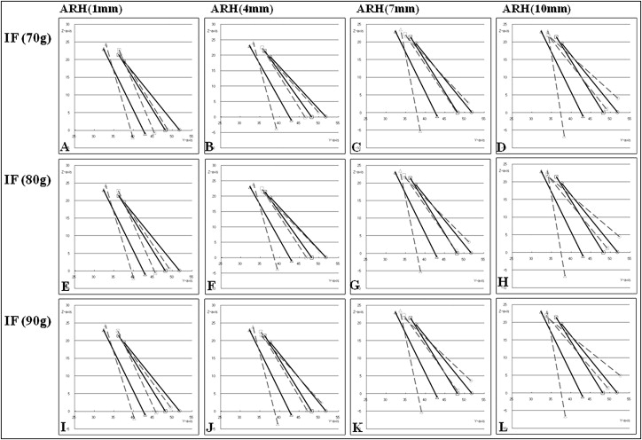
We assumed that there were no gaps between the bracket and the archwire at the central incisor, lateral incisor, and canine and carried out the nonlinear analysis, allowing the gap element between the archwire and the 0.8-mm diameter hole of the C-implant head. The intrusion force can be applied to 1 point between the central incisors or 2 points between a central incisor and a lateral incisor; in this study, we applied the intrusion force to 1 point between the central incisors. The retraction force was applied via ARH between a lateral incisor and a canine. The retraction force was 150 g between the ARH and the C-implant head, and the lengths of hooks were 1 mm (very short), 4 mm (short), 7 mm (standard), and 10 mm (long). We measured the intrusion forces by using 3 curved NiTi wire sizes (0.016 × 0.022-in, 0.017 × 0.025-in, and 0.019 × 0.025-in) (G&H Wire, Franklin, Ind) according to the intraoral condition of patients and obtained 70, 80, and 90 g, respectively. The intrusive force was applied between the right and left central incisors in the +z direction as in a 1-piece intrusion archwire. The boundary condition for holding the maxillary model was the top of the model base connected to the maxilla. There was significant clearance in the 0.8-mm hole of the C-implant head, so friction for all 3 wires was low. The differences in friction between the wire sizes were not significant. The graphs are labeled with the forces produced as measured on the physical models ( Fig 3 ). The tooth displacements were marked by applying the x, y, and z coordinates at the midpoint of the incisal edges of the central incisor and lateral incisor, the cusp tip of canine, and each tooth’s root apex.
For the FEA, ANSYS (version 11, Swanson Analysis System), the universal finite element program, was used on a workstation (HP XW6400, Hewlett-Packard, Palo Alto, Calif).
Results
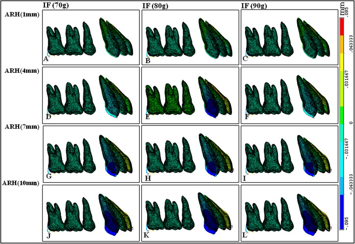
We observed the tooth displacement pattern on the z-axis ( Table II , Figs 3 and 4 ) based on the movement of the maxillary central incisal edges. The amount of intrusion increased as the intrusion force increased and the length of the hook increased. Because the force system introduces a slight counterclockwise moment to the anterior dental segment, we noticed some canine extrusion, which decreased with a heavier intrusion force and increased with a longer hook arm.
| Intrusion force (g) | |||||
|---|---|---|---|---|---|
| Tooth | Hook length | 70 | 80 | 90 | |
| Central incisor | 1 mm | Root apex | 2.78E-02 | 2.69E-02 | 2.60E-02 |
| Incisal edge | 1.89E-03 | 7.91E-03 | 1.39E-02 | ||
| 4 mm | Root apex | 2.70E-02 | 2.64E-02 | 2.57E-02 | |
| Incisal edge | 2.03E-02 | 2.61E-02 | 3.21E-02 | ||
| 7 mm | Root apex | 2.84E-02 | 2.77E-02 | 2.70E-02 | |
| Incisal edge | 3.82E-02 | 4.42E-02 | 5.01E-02 | ||
| 10 mm | Root apex | 2.93E-02 | 2.86E-02 | 2.79E-02 | |
| Incisal edge | 5.63E-02 | 6.23E-02 | 6.83E-02 | ||
| Lateral incisor | 1 mm | Root apex | 1.91E-02 | 1.91E-02 | 1.91E-02 |
| Incisal edge | −1.18E-02 | −8.92E-03 | −6.08E-03 | ||
| 4 mm | Root apex | 1.58E-02 | 1.57E-02 | 1.57E-02 | |
| Incisal edge | −1.89E-03 | 8.32E-04 | 3.54E-03 | ||
| 7 mm | Root apex | 1.17E-02 | 1.16E-02 | 1.16E-02 | |
| Incisal edge | 6.24E-03 | 8.95E-03 | 1.17E-02 | ||
| 10 mm | Root apex | 7.46E-03 | 7.40E-03 | 7.33E-03 | |
| Incisal edge | 1.46E-02 | 1.73E-02 | 2.00E-02 | ||
| Canine | 1 mm | Root apex | 1.95E-02 | 1.89E-02 | 1.83E-02 |
| Incisal edge | −1.52E-02 | −1.47E-02 | −1.43E-02 | ||
| 4 mm | Root apex | 1.40E-02 | 1.34E-02 | 1.28E-02 | |
| Incisal edge | −3.80E-02 | −3.75E-02 | −3.70E-02 | ||
| 7 mm | Root apex | 7.36E-03 | 6.73E-03 | 6.10E-03 | |
| Incisal edge | −5.97E-02 | −5.92E-02 | −5.88E-02 | ||
| 10 mm | Root apex | 5.21E-04 | −1.09E-04 | −7.39E-04 | |
| Incisal edge | −8.07E-02 | −8.03E-02 | −7.98E-02 | ||