A procedure performed with the most adept hands, with technical perfection, is all for naught if the procedure is not appropriate to that patient’s needs. The first step for the cosmetic surgeon to take on this path is to develop a treatment plan. Cosmetic treatment planning is determining the patient’s anatomic concerns, expectations, psychological stability, and financial and recovery limitations and then tailoring the most suitable intervention in accordance with these factors.
During the initial consultation with a prospective patient for aesthetic surgery, the cosmetic surgeon must be devoted to understanding the psychological framework and aesthetics of the patient. The patient’s motivations, complaints, expectations, and support system are all important in determining whether he or she is a good surgical candidate. The surgeon becomes skilled at recognizing prospective problem patients. The acronym SIMON ( s ingle i mmature m ales o verexpectant n arcissistic) was created by Gorney to identify potential problem patients. A second tool of evaluation is plotting the patient’s concerns to the degree of deformity. The two elements should be relatively close. A small degree of deformity and a large emotional concern do not combine to make a good surgical candidate.
Gunter identified 13 red flags that identify a potential problematic patient with possible psychological issues: (1) minimal disfigurement, (2) identity problem of sexual ambivalence, (3) delusional view of body image, (4) unrealistic life change as result of surgery, (5) confused motives for wanting surgery, (6) history of poor relationships, (7) unresolved grief or current crisis, (8) older neurotic man overly worried about aging, (9) paranoid thoughts, (10) history of dissatisfaction from multiple physicians, (11) sudden dislike for one’s anatomy, (12) hostile attitude toward authority figures, and (13) present misfortunes blamed on appearance.
Body dysmorphic disorder (BDD) is thought to affect 1-2% of the general population. Various surveys have shown a range of 7-16% of patients seeking cosmetic surgery could be diagnosed with BDD. According to the Diagnostic and Statistical Manual of Mental Disorders, Fourth Edition, BDD is characterized as (1) preoccupation with an imagined or slight defect; (2) significant distress or impairment in social, occupational, or other areas of functioning as a result of the preoccupation; and (3) an appearance preoccupation that is not better accounted for by another disorder. Patients with BDD who are treated with surgery do not improve and many times may worsen. The cosmetic surgeon should identify such patients and treat them correctly and ethically.
Listening to the patient’s desires and concerns is of paramount importance. When evaluating the patient, plugging the patient’s anatomic findings into an algorithm to correct something the patient does not necessarily want correcting is too easy.
Imaging software has been found to be a valuable tool during consultations in developing a shared vision with a patient. Surgeons should explain to the patient that any computer-enhanced, altered image is not a guarantee of final product, and the patient should sign a document acknowledging this explanation. With this computer software the surgeon and patient together look at the preoperative pictures and together determine points of concern.
In determining what procedures best suit a particular patient, two points must be considered. First, the face is a dynamic system of muscles coordinating movement. Altering the position or function of one structure will have an impact on neighboring structures. This is a lesson learned from orthognathic surgery. Second, when evaluating any patient for an improvement in cosmesis, measuring the face in proportions is necessary; do not rely on the measurements themselves. This chapter addresses the interplay of procedures that have already been described in this text and how multiple procedures and techniques often work better in synergy than alone.
CHIN IMPLANTS: INTRAORAL OR EXTRAORAL PLACEMENT
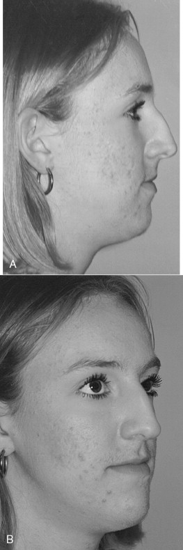
This 24-year-old woman presented with complaints about the profile view of her nose ( Figure 33-1 ).
When evaluating any patient from a lateral view, one must consider the relation of the face in a vertical and anterior/posterior direction. Facial beauty relates to balance and harmony in size and volume in all three dimensions.
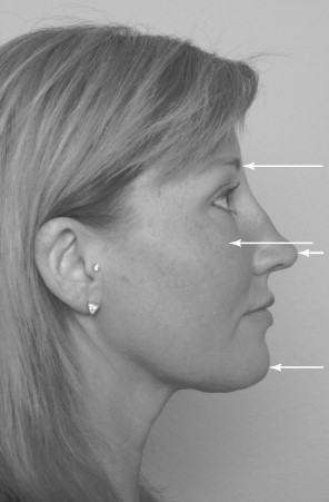
Four major points of protrusion exist when viewing the profile of the face: the forehead/brow, malar prominence, nose, and chin ( Figure 33-2 ). These eminences provide topographic changes that give definition to the face. These changes are found as creases, folds, and depressions.
EVALUATION AND OPTIONS
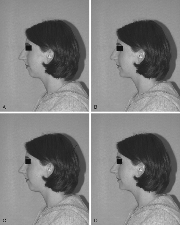
Photographs of this patient clearly show an inharmonious relation between the middle and lower thirds of her face. This relation is seen on her prominent dorsal hump and convex facial profile. The fact that she has dorsal excess and a genial deficiency should be explained to the patient. The ideal treatment to provide facial balance is a rhinoplasty and chin augmentation. The changes in her profile with an isolated rhinoplasty, isolated chin advancement, or combination chin and rhinoplasty can be demonstrated with imaging software ( Figure 33-3 ). Her discrepancy can be measured from a lateral cephalometric radiograph.
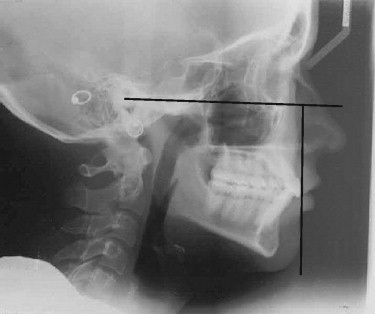
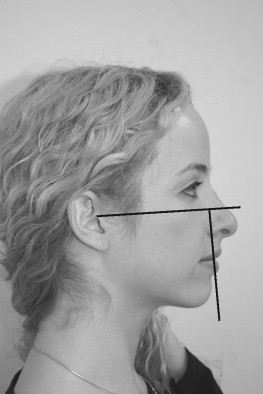
Many surgeons have published landmarks that have proven to be successful for them when planning a chin advancement ( Table 33-1 ). A quick, easy, and reliable method for determining soft tissue chin position, as described by Epker, uses a line drawn perpendicular to Frankfort horizontal on the most anterior surface of the upper central incisor. The soft tissue chin should fall at or posterior to that line by less than 2 mm ( Figure 33-4 ). A chin point falling posterior to this line is more acceptable for a woman than a man. With a 1-mm advancement, a soft tissue advancement of 0.7 mm can be expected. If a lateral cephalogram is not available, a lateral photograph can suffice. Cuzalina speaks of drawing a line on the photographic profile parallel to Frankfort horizontal. A line is then dropped perpendicular, touching the junction of the upper and lower lips. The soft tissue chin should be coincident with this. This is a quick, easy, and reliable assessment for chin deficiency that can easily be demonstrated to a patient ( Figure 33-5 ).
Different surgical options for chin augmentation should be considered, such as an osteotomy for a genioplasty with rigid fixation compared with an alloplast to augment the chin. Different alloplastic materials are available for this type of procedure. The incisions for this can be performed intraorally or extraorally.
Scales has described the properties of the “ideal” implant. It should be chemically nonreactive, devoid of a foreign body reaction, nonallergenic, noncarcinogenic, resistant to deformation, sterilizable, and easily fabricated and modified with predictable and reproducible results as well as not be physically modified by soft tissue.
Synthetic alloplastic materials can be broadly categorized into carbon-based polymers, non-carbon-based polymers, aliphatic polyesters, metals, and ceramics ( Box 33-1 ). Among the most popular facial implants used today is the silicone implant (Silastic, Dow Corning Corp., Midland, Mich.). This is a non-carbon-based polymer that is inert and becomes encapsulated by the host. It is popular most likely because of its soft and flexible consistency and, most importantly, its nonporous composition. An infection that may develop usually can be treated with a course of antibiotics. Other porous implants such as hydroxyapatite and Mepore (Mölnlycke Health Care AB, Göteborg, Sweden) may need complete removal to be treated effectively.
Carbon-Based Polymers
Polytetrafluoroethylene (Gore-Tex)
High-density polyethylene (Medpore)
Methylmethacrylate
Non-Carbon-Based Polymer
Silicone (Silastic)
Metal
Titanium
Ceramic
Hydroxyapatite
In general, 1 × 10 5 bacteria are needed to cause clinical manifestations of an infection. In the environment of a foreign body, the number is reduced to only 100 bacteria. Antibiotic coverage should be considered both intravenously and postoperatively enterally, and the implant itself should be soaked in antibiotic solution before replacement.
Advantages of an alloplastic chin implant over an advancement by osteotomy include a limited dissection, less pain, and ease of placement. More palpable notching at the posterior border between the two segments of bone has been observed in the osteotomized patient. In addition, the deepening of the labiomental groove seen in the patient with a genioplasty through an osteotomy can be corrected much easier with an alloplastic implant.
Disadvantages of the alloplastic chin implant include its limitations in addressing vertical discrepancies, potential for mobility as a foreign body, and reports of bone resorption beneath the implant. When placed in a subperiosteal plane, and with some types of fixation, the mobility and resorption do not present a problem. Anatomic pre-jowl implants provide natural contour to the chin in both anterior and lateral augmentation ( Boxes 33-2 and 33-3 ).
Advantages
Easily reversible
Quicker recovery time
Less painful
Less chance of paresthesia
Can address pre-jowl sulcus
Disadvantages
Overaugmentation
Malposition
Lateral limb malposition
Extrusion (rare)
Bone resorption
Horizontal deficiency
Advantages
Can change vertical dimension
Better for asymmetry
Disadvantages
Deeper anesthesia
More equipment and hardware
Painful, more dissection
Greater risk of IAN injury
Risk to dental roots
Overaugmentation
Longer surgery time
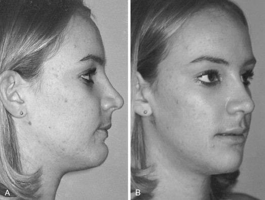
The chin implant can be placed by an intraoral approach or through an incision below the submental crease. The extraoral approach probably is more popular, but both are effective and have their benefits and limitations ( Boxes 33-4 and 33-5 ). The patient described in this case benefited from an open rhinoplasty and chin augmentation with an allograft placed extraorally ( Figure 33-6 ).
Advantage
No external scar
Disadvantages
Chance of lip incompetence
Greater change of vertical migration
Greater chance of infection
Advantages
Preserves mentalis muscle
Less chance of bacterial contamination
Less chance of migration
Disadvantage
Chance of scar
“I lost 150 pounds and have all this extra skin on my neck.”
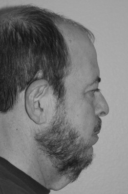
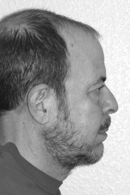
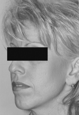
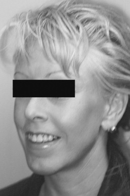
A 58-year-old man who lost a substantial amount of weight complained of excessive tissue in his neck area, which he addressed by wearing a beard ( Figure 33-7 ). Aside from a large volume of excessive skin, platysma laxity, a small chin, and a low-placed hyoid bone are noted. An isolated neck lift would not attain good success. Procedures that would benefit this patient include a skin excision, platysma plication, and chin advancement or implant to provide a more acute cervicomental angle.
Addressing the skin solely with a postauricular incision would probably not satisfy the patient’s expectations. Therefore an anterior neck skin incision was performed. A man with a beard is a suitable candidate for this technique because the scar can be hidden.
In this case, advancing the chin by geniotomy is more successful for tightening the neckline by stretching the digastric muscles than a chin implant would be. The patient did not accept the risk of transoral geniotomy, and the neck incision provided good access for implant placement.
The procedure was performed by first drawing a line just posterior to the submental crease. A puncture incision was created on either side of the line and a supraplatysmal plane was created with a V notch dissector. Similarly, the same plane was created from the posterior auricular approach as performed in submental liposuction. The anterior incision was then opened.
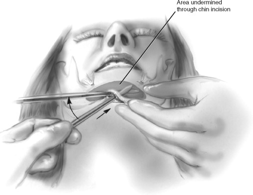
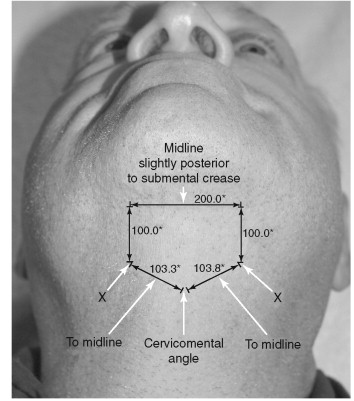
A chin implant was placed by an extraoral approach. The surgical approach for the extraoral placement of an alloplastic implant begins with identifying and marking the chin midline and submental crease. Creating the incision just posterior to this crease is best to avoid a “witch’s chin” deformity. The incision made is approximately 1.5 cm in length. A skin hook is placed in the midline and the incision is advanced superior to allow dissection with a fine tip Bovie (Bovie Medical Corporation, St. Petersburg, Fla.) anterior and superior to the symphysis. Once the symphysis is encountered, the periosteum is scored and the subperiosteal plane is created. A blunt, elongated periosteal elevator is used to create a subperiosteal tunnel along the anterior inferior border. Using the free hand to palpate the border helps with the dissection to ensure a plane beneath the mental nerves. The mental nerve is 1 cm from the inferior border of the mandible and 25 to 27 mm lateral to the midline (between and below the apices of the roots of the premolars) ( Figure 33-8 ). The dissection should extend posteriorly to the first molar.
The implant is soaked in gentamycin solution, followed by povidone-iodine with minimal hand manipulation before placement. The midline is marked and the implant is placed in the subperiosteal tunnel, one side at a time. The periosteal elevator is used to guide the implant into the correct position and ensure the midline is lined up to the facial midline previously identified. A 2-0 resorbable suture is placed through the implant and sutured to the periosteum. The implant may be secured with a metallic screw. The wound is closed in layers. The skin is then closed with 5-0 nylon sutures in a running fashion. A compression dressing should be placed to prevent hematoma, ensure stability, and provide comfort for the patient.
The platysmal desiccation was excised vertically and the two ends of anterior platysma were approximated with a double-layer closure of polyglycolic acid sutures. Some variation in the midline of platysma desiccation exists among individuals. Cardoso de Castro found that 1 to 2 cm inferior to the mandibular symphysis a decussation was noted 75% of the time. A total of 15% had this decussation between the thyroid cartilage and mandibular border, and the remaining 10% had no decussation. The variation among patients receiving a neck lift is clinically insignificant. Proper identification of the medial running edge of the platysma is important to suspend, resect, or support the neck effectively.
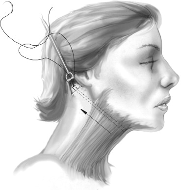
The hyoid bone was dissected and plicated to the newly tightened platysma. A Giampapa suture was placed on the anterior aspect of the left medial free end and tunneled to the right posterior auricular incision. This suture was tied to the periosteum overlying the mastoid process. This was performed on the contralateral side with 3.0 nonresorbable suture ( Figure 33-9 ). The skin was then pulled posterior and the excess skin was removed. The skin was reapproximated with 3.0 chromic stay sutures.
A pentagon-shaped incision (“home base”) was outlined and skin was excised. The corners of the pentagon were reapproximated ( Figures 33-10 and 33-11 ). The patient has a small midline scar well hidden by facial hair.
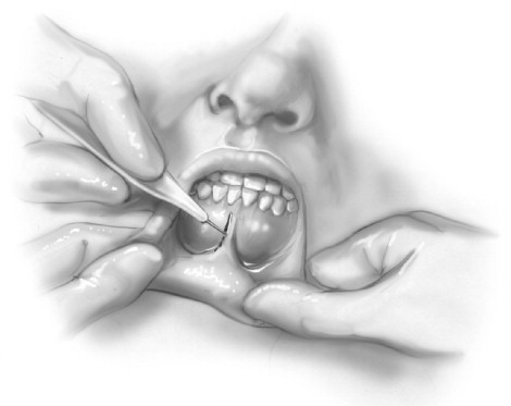
If the desire of the patient or the surgeon is the placement of the implant through an intraoral approach, a standard genioplasty incision can be used. An incision that the author has used with great success is a midline incision ( Figure 33-12 ). The lip is everted with one hand, and a 1- to 1.5-cm vertical incision is made with the other hand through the vestibule and the mentalis muscle. A periosteal elevator is used to identify the subperiosteal plane and the larger Obwegeser elevator (Biomet Microfixation, Jacksonville, Fla.) can be used to create the tunnel, with the free hand supporting the inferior border of the mandible. The implant through this incision has a tendency to slide superiorly. An implant situated in a position just superior to the inferior border is more acceptable in a woman. Screw fixation can be used to maintain the implant in the proper position. This approach limits dissection, limits scarring, minimally disrupts the mentalis muscle, causes no embarrassment of the muscle attachment, and allows a quick entry and closure. To date no published data have shown an increased rate of infection through an intraoral approach, although intuitively, one may think the opposite.
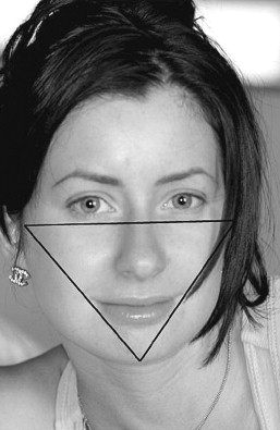
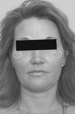
A 43-year-old woman wanted to undergo cosmetic surgery to draw more attention to her eyes ( Figure 33-13 ). When the face is assessed in a front view it can be considered a triangle, with the corners as the chin and zygomatic eminence ( Figure 33-14 ). An attractive face often has well-defined corners of the triangle and hence a well-proportioned chin and cheekbones. Malar implants can be a valuable adjunct to facial cosmetic surgery.
The treatment plan for this patient was an endoscopic brow lift, closed rhinoplasty, and malar implants. These three procedures work in harmony to produce the desired result. The endoscopic brow lift repositions the brow to the proper bony landmark, which helps open the eyes. When following the eyebrow over the orbital bar and into the bridge of the nose, the dorsal bump of this patient’s nose disrupts the continuity. This disrupts the more attractive features on the patient’s face, such as her eyes. A closed rhinoplasty to reduce the dorsal hump creates the desired smoothness. Malar implants fill the zygomatic eminence and create definition of the facial triangle ( Figure 33-15 ).
Malar implants can be used alone or as an important adjunct in providing a successful result. For example, in the patient who has undergone rhytidectomy, skin can appear tense and bland without proper topography of the malar region. By augmenting the malar area, a tenting effect can be seen on the overlying skin that gives a natural and beautiful draping effect that adds needed definition to many facelifts. Facial implants provide 3D change, whereas facelifts allow for only two.
Different analyses have been reported to determine the proper projection of the malar region, albeit no one method is superior to another. This likely is because of the 3D nature of the zygoma combined with its 2D analyses. This area of the face can be appreciated in different angles in photographs but is best appreciated in multiple dimensions in person ( Table 33-2 ).
| Hinderer | From the frontal view, draw a line from the lateral commissure of the lip to the lateral canthus of the ipsilateral eye and another line from the tragus to the inferior edge of the nasal ala. The area posterior and superior to the junction of these two projections should be the most prominent area of the malar eminence. |
| Powell et al | Draw a vertical line through the middle of the face, then bisect the segment between the nasion and the nasal tip with a line that curves gently upward to the tragus on both sides. Draw a line from the inferior ala to the lateral canthus and another one, parallel to this one, from the lateral oral commissure toward the ear. The intersection of the curvilinear horizontal line and the line from the oral commissure marks the point where the malar area should be most prominent. |
| Silver and Guilden | If the malar prominence in the true lateral projection is >5 mm posterior to the nasolabial groove, then a deficiency in the malar area exists. Silver describes the malar prominence triangle. To create this triangle, draw a Frankfort horizontal line across the face in frontal projection and a parallel line that bisects the upper lip. Then draw a perpendicular line through both of these lines and through the lateral canthus. The intersection of the vertical line and the line through the upper lip defines point A. Create a line from point A though the medial canthus and then a second line from point A toward the temporal area—but at the same angle from the vertical that was created by the projection from point A through the medial canthus. This creates the malar prominence triangle with the base being the Frankfort horizontal and the apex being point A. Silver advises that the implant should be placed several millimeters below the Frankfort line. |
| Schoenrock | On an oblique view (27 to 35 degrees of rotation from the frontal view) in natural head position, a line drawn through lateral canthus and the mentum should reveal the “width” of the malar eminence. This is said to be approximately 3 to 7 mm in the average person. |
When augmentation of the malar prominence is needed, it usually is in the area inferior and lateral to the lateral canthus, as shown in Figure 33-16 .
Stay updated, free dental videos. Join our Telegram channel
VIDEdental - Online dental courses


