The aim of this study was to fabricate a resin appliance incorporating “wire” components without the use of an analog impression and dental casts using an intraoral scanner and computer technology to build the appliance. This unique alignment of technology offers an enormous reduction in the number of fabrication steps when compared with more traditional methods of manufacture. The prototype incorporated 2 Adams clasps and a fitted labial bow. The alloy components were built from cobalt-chromium in an initial powdered form using established digital technology methods and then inserted into a build of a resin base plate. This article reports the first known use of computer-aided design and additive manufacture to fabricate a resin and alloy appliance, and constitutes proof of the concept for such manufacturing. The original workflow described could be seen as an example for many other similar appliances, perhaps with active components. The scan data were imported into an appropriate specialized computer-aided design software, which was used in conjunction with a force feedback (haptic) interface. The appliance designs were then exported as stereolithography files and transferred to an additive manufacturing machine for fabrication. The results showed that the applied techniques may provide new manufacturing and design opportunities in orthodontics and highlights the need for intraoral-specific additive manufacture materials to be produced and tested for biocompatibility compliance. In a trial, the retainer was fitted orally and judged acceptable by the clinician according to the typical criteria when placing such appliances in situ.
Highlights
- •
Orthodontic clasps can be built with intraoral scans and without dental casts.
- •
Orthodontic clasps and other alloy components can be embedded in a resin base.
- •
Scanning would eliminate some problems of conventional impression taking.
- •
Scanning would eliminate the costs associated with storing casts.
Computer-aided design/additive manufacturing (CAD/AM) systems have been introduced successfully in various areas of dentistry. In orthodontics and related areas, they have been used for building and inserting a preformed wrought labial bow in a build of an Andresen appliance and for building a sleep apnea device with 4 rotating hinges in a single build. CAD/AM has also been used to build customized removable appliances without wires or brackets (Invisalign; Align Technology, Santa Clara, Calif) and to produce customized brackets fitted on the lingual surfaces of teeth.
In this study, CAD/AM technology was used to fabricate a retainer incorporating Adams clasps and a fitted labial bow from an intraoral scan without using dental casts. Digital scanning of the teeth and surrounding mucosa of a whole arch was required using an intraoral scanner (TRIOS; 3Shape, Copenhagen, Denmark) to build the retainer in the virtual environment.
The aim of this study was to uniquely apply intraoral scans and CAD/AM techniques to fabricate dental appliances with alloy components without the use of conventional impressions and dental casts. This is considered a step toward improving the production efficiency and the quality of intraoral devices because it does not use an impression material, which has the potential for distortion and inaccuracies. A retainer incorporating Adams clasps and a fitted labial bow was fabricated in this study. The following illustrates how certain types of appliances and devices can be built using computer technologies.
Material and methods
Dental 3-dimensional (3D) scans of a patient were taken using an intraoral scanner (TRIOS). The images were captured and directly converted into stereolithography (STL) files using the scanner’s software (VX elements version 2.1; 3Shape). The STL files were imported into specialist CAD software (version 12, Geomagic Freeform Modeling Plus; 3D Systems, Rock Hill, SC) with the “fill holes” option. This software was chosen because it has been widely used for designing anatomically based devices. It was used in connection with a phantom desktop (haptic) arm (Geomagic; 3D Systems). The device is now known as a Geomagic Touch X.
The term “clay” is used to describe the virtual material that can be sculpted and modified in the Freeform software. “Buck clay” refers to the material in the virtual environment that cannot be modified while working virtually, thus preserving the original shape on which a device can be designed. Any sculpted material can be saved as a buck file if required.
Initially, unwanted undercuts were eliminated automatically in a similar way to that described in previous study and denote a form of virtual surveying.
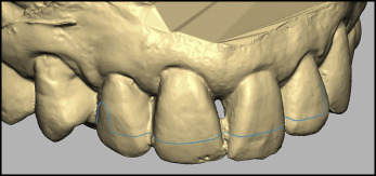
Building Adams clasps in CAD was accomplished by creating clay in clasp shapes according to an underlying positioned line. Circular cross-sectioned clay of 0.6 mm was selected to simulate the outline of a wire clasp. The curves representing the Adams clasp and the fitted bow were drawn with the “curve” tool.
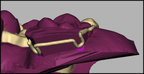
The curve of the fitted labial bow was drawn on the scan directly because the clay representing the wire must be fitted to the teeth. This was a relatively straightforward operation. The same is not true of Adams clasps, for which a more complex approach was necessary. The arrowheads and the bridge of the clasp must not be in contact with the tooth except in undercut areas and with some contact at the occlusal surface. To achieve this, it was again necessary to use clay in the required spaces between the tooth surface and the clasp ( Fig 1 ).
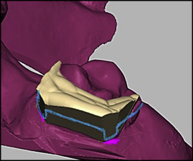
The clay for the Adams clasp was produced by creating planes on which to draw it ( Fig 2 ). Plane A was created and formed 45° with the buccal surface of the tooth on which the bridge of the Adams clasp would be drawn. Planes B and C represent the mesial and distal surfaces on which the crossover lines will be drawn. Planes D and E form 45° with plane A , and these formed the area where the arrowhead curves will be drawn.
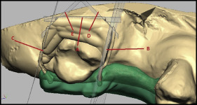
The clay built from these planes effectively formed a spacer on which an Adams clasp could be created, and the whole was later saved as a protected buck model ( Fig 2 ).
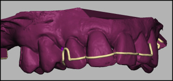
The clasps were drawn in outline by a line on the buck model, which at this stage included the spacers for the clasps. A wire shape of appropriate diameter was defined along this line by the software using the “ridge” tool ( Figs 3 and 4 ). A final diameter of 0.7 mm is normally required, but a greater thickness should be produced at this stage to allow for the loss of material in the finishing process.
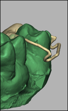
The fitted labial bow was drawn on the buck cast ( Fig 5 ) and transformed to circular profile clay by the CAD software using the “ridge” tool ( Fig 6 ).