Introduction
The purpose of this study was to test the null hypothesis that dolichofacial and brachyfacial children with Class II malocclusion do not differ in upper airway obstruction. Furthermore, the ability of fluid-mechanical simulation to detect airway obstruction within the limitations of simulation was examined.
Methods
Forty subjects from 7 to 11 years of age with Class II malocclusion participated and were divided into 2 groups, dolichofacial and brachyfacial, based on their Frankfort mandibular plane angles. Cone-beam computed tomography images supplied the shape of the entire airway. Two measures of respiratory function, air velocity and pressure, were simulated by using 3-dimensional images of the airway. The images and simulations were compared between the 2 facial types.
Results
The size of the upper airway did not differ statistically between facial types; however, the simulated maximal pressure and velocity of the dolichofacial type were significantly higher than those of the brachyfacial type.
Conclusions
Airway obstruction differs with the Frankfort mandibular plane angle, even though the depth and cross-sectional area of the airway do not. The fluid-mechanical simulation system developed in this study detected differences in airway obstruction that were not apparent from morphologic studies.
Upper airway narrowing is implicated in the development of obstructive sleep apnea (OSA). The importance of this obstruction during childhood is increasingly recognized. Children with OSA often have excessive daytime sleepiness, hyperactivity, attention deficit disorder, poor hearing, physical debilitation, and failure to thrive. Accordingly, much attention has been paid to the influence of maxillofacial form on respiratory function during growth. Some studies have suggested that Class II malocclusion is associated with mouth breathing. In other studies, a vertical growth pattern, with obstruction of the upper and lower pharyngeal airways, has been associated with mouth breathing. Comparing subjects with normal occlusion and Class II malocclusion, Kerr found a slight correlation between the nasopharyngeal airway (NA) and dentofacial structures when the nasal functions were normal. In contrast, Freitas et al found the NA to be closely associated with vertical maxillofacial growth when comparing dentofacial structures between Class II children with and without excessive vertical growth.
Some studies concluded that mouth breathing influences maxillofacial growth, but others found no relationship. The different conclusions might be related to inaccurate evaluation of airway size with 2-dimensional lateral cephalograms. To better evaluate the relationship between the respiratory function and airway morphology, we propose using fluid-mechanical simulation (FMS) to evaluate the ventilation condition of the whole upper airway.
The purpose of this study was to clarify the relationship between upper airway obstruction and vertical maxillofacial growth by using FMS. Because the dolichofacial type represents vertical maxillofacial growth and the brachyfacial type represents horizontal growth, a comparison between the 2 can clarify the relationship between upper airway obstruction and vertical maxillofacial growth. The tested null hypothesis was that dolichofacial and brachyfacial children with Class II malocclusion do not differ in their degrees of upper airway obstruction. Furthermore, the ability of FMS to detect upper airway obstruction within its limitations was examined.
Material and methods
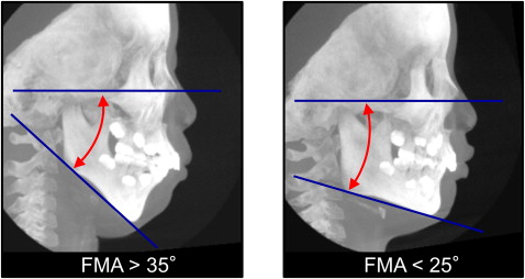
Forty patients, who visited an orthodontic office in Himeji, Japan, for treatment for Class II malocclusion, participated in this study. The subjects were divided into 2 groups according to their Frankfort mandibular plane angle (FMA): dolichofacial Class II malocclusion patients (FMA, >35°) and brachyfacial Class II malocclusion patients (FMA, <25°) ( Fig 1 ). The dolicofacial and brachyfacial groups consisted of 7 boys and 13 girls (average age, 9.5 ± 1.0 years) and 10 boys and 10 girls (average age, 9.4 ± 1.2 years), respectively.
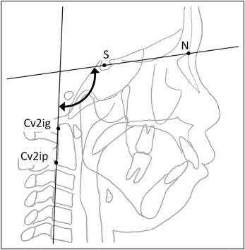
Because the volume of the airway is influenced by head posture, craniocervical inclinations of all subjects were examined to ensure that their inclinations were between 90° and 110°. The craniocervical inclinations were calculated as the angle between the nasion-sella line and a line through Cv2ig and Cv2ip; Cv2ig is the tangent point at the superior posterior extremity of the odontoid process of the second cervical vertebra, and Cv2ip is the most inferior posterior point on the body of the second cervical vertebra ( Fig 2 ).
Clinically, mouth breathing was defined as a pneumatic flow from the mouth during quiet breathing. We defined the following respiratory patterns that might influence maxillofacial form: (1) obstructive mouth breathing, an obstructive mouth breather breathes through the mouth because of an obstruction in the airway; (2) habitual mouth breathing without obstruction, a habitual mouth breather breathes through the mouth even though there is no obstruction in their airway; and (3) nasal breathing with open-mouth posture.
Each subject was seated in a chair with his or her Frankfort horizontal plane parallel to the floor. A cone-beam computed tomograph (CB MercuRay, Hitachi Medical, Tokyo, Japan) was set to maximum 120 kV, maximum 15 mA, and exposure time of 9.6 seconds. Data were sent directly to a personal computer and stored in digital imaging and communications in medicine (DICOM) format ( Fig 3 ). Before the computed tomography (CT) scans, the parents of the patients were fully informed of the purpose and the risk of CT scans. The study was reviewed and approved by the ethics committee of the Kagoshima University Graduate School of Medical and Dental Sciences, Kagoshima, Japan.

A 3-dimensional (3D) coordinate system and a 3D image were constructed with a medical image analyzing system (ImagnosisVE, Kobe, Japan). The origin of the 3D coordinate system was the midpoint between the left and right porions. This origin and the left and right orbitales defined the standard horizontal plane. A frontal plane was constructed through both orbitale points perpendicular to the Frankfort horizontal plane. A sagittal plane was constructed through both orbitale midpoints and perpendicular to the horizontal and frontal planes. From these constructed cephalometric images, the anteroposterior positions of both the maxilla and the mandible were evaluated with SNA angle, SNB angle, ANB angle, FMA, overjet, and overbite ( Table I ).
| Dolichofacial type (n = 20) |
Brachyfacial type (n = 20) |
||||
|---|---|---|---|---|---|
| Mean | SD | Mean | SD | P value | |
| SNA (°) | 80.48 | 3.01 | 82.15 | 3.46 | 0.149 |
| SNB (°) | 72.83 | 3.12 | 75.03 | 3.38 | 0.035 |
| ANB (°) | 7.65 | 1.57 | 7.13 | 1.19 | 0.314 |
| FMA (°) | 36.22 | 2.07 | 21.78 | 2.19 | <0.001 ∗ |
| Overjet (mm) | 7.35 | 2.46 | 7.60 | 2.60 | 0.883 |
| Overbite (mm) | 4.40 | 1.79 | 5.30 | 1.87 | 0.102 |
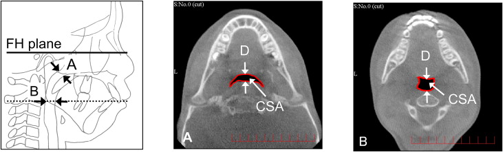
Airway cross-sectional parameters, including cross-sectional area (CSA) and depth (anteroposterior direction), were measured at the NA and oropharyngeal airway (OA) ( Fig 4 ). These parameters for the sizes of the NA and the OA were based on a previous report. The NA cross-section was defined as lying in a horizontal plane along the narrowest part of the nasopharynx in the constructed lateral cephalometric image ( Fig 4 , A ). The OA cross-section was defined as lying in the horizontal plane through the midpoint of the bilateral gonion ( Fig 4 , B ).
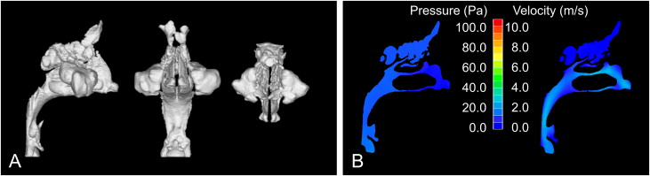
Our method simulates turbulent flow to estimate virtual airflow patterns in the upper airway ( Fig 3 ). Volume rendering software (INTAGE Volume Editor, CYBERNET, Tokyo, Japan) was used to create the 3D images of the shape of the upper airway. Because the airway is void space surrounded by hard and soft tissues, inversion of the 3D rendered image is required; this converts a negative value to a positive value, and vice versa. Inversion removes the hard and soft tissues from the image and displays only the upper airway. Subsequently, threshold values were adjusted to eliminate imaging artifacts and to refine the selected airway region. By using an appropriate smoothing algorithm with a moving average, the 3D model was converted to a smooth model without losing the patient-specific character of the upper airway shape. The rendered volume data was in a 512 × 512 matrix with a voxel size of 0.377 mm. The 3D cone-beam CT (CBCT) images for the airway model were exported to computational fluid-dynamic software (PHOENICS, CHAM-Japan, Tokyo, Japan) in stereolithographic format. The construction of the 3D model takes about 15 minutes.
Airway resistance is greater during expiration than inspiration during quiet breathing. Accordingly, each voxel on the plane of the hypopharynx was considered part of the flow inlet, whereas each voxel at the entrance of each nostril was considered part of the flow outlet. The air was assumed to be a newtonian, homogeneous, and incompressible fluid. Elliptic-staggered equations and the continuity equation were used in the study. The following boundary conditions were set to the model: (1) the air flow perpendicular to the lower pharyngeal plane had a velocity of 200 mL per second, (2) the wall surface was nonslip, and (3) the simulation was repeated 1000 times to calculate the mean values. Convergence was judged by monitoring the magnitude of the absolute residual sources of mass and momentum, normalized by the respective inlet fluxes. The iteration was continued until all residuals fell below 0.2%. With our system, the FMS analysis takes about 6 hours.
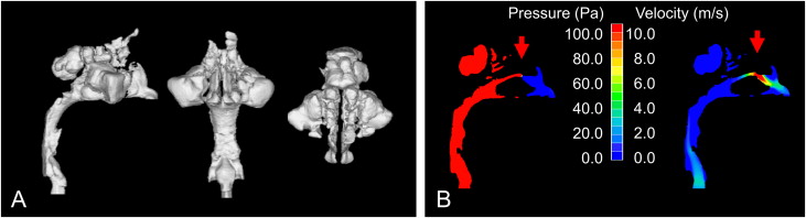
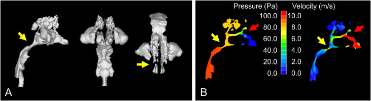
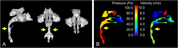
The results of the FMS are shown as pressure and velocity. The maximum pressure and the maximum velocity of the upper airway were calculated to evaluate the ventilatory condition. In addition, detection of obstructions in the upper airway is shown in Figures 5 through 8 . A previous study showed upper airway obstruction when the resistance was above 5.0 cm of water per liter per second, and that the pressure (upper airway resistance flow) in children with nasal breathing difficulty is greater than 100 Pa (1 Pa ≒ 0.01 cm of water) with an inflow of 200 mL per second. The place where the 3D images from the CBCT were completely perforated was considered obstructed. An obstruction in the upper airway was also indicated by an abrupt pressure decrease and high velocity in the FMS.
Statistical analysis
For each measurement, either an unpaired t test or a Mann-Whitney U test was used to detect between-group differences, depending on the data distribution. The criterion for an obstruction was a maximal pressure of more than 100 Pa, and the frequency of obstruction was compared between facial types by using the Fisher exact test. For all tests, P <0.05 was considered statistically significant.
The reliability of the measurements (intraoperator repeatability) was assessed first by repeated tracings (landmark identification) and then by digitization of the same lateral cephalograms. To assess the error in landmark identification, 10 randomly selected lateral cephalogram images from the 40 were traced and digitized twice by the same operator (T.I.) within 1 week.
Calculations were also performed independently for each digitization, the differences between paired linear measurements were calculated, and Dahlberg’s error (double determination method) was computed. The measurement errors for the cephalometric images ranged from 0.433 to 0.487 mm (mean error, 0.460 mm) and from 0.387° to 0.559° (mean error, 0.502°), indicating that these errors were negligible. The method errors were 1.67 mm 2 and 0.44 mm for cross-sectional area and depth for the NA, respectively, and 1.56 mm 2 and 0.14 mm for the OA, respectively. According to all repeated analyses, the method error was considered negligible.
Results
The depth of the NA in the dolichofacial type (6.96 ± 2.83 mm) did not differ significantly from that of the brachyfacial type (8.67 ± 2.65 mm) ( Table II ). The cross-sectional area of the NA in the dolichofacial type (159.96 ± 72.17 mm 2 ) was significantly smaller in the brachyfacial type (213.45 ± 64.22 mm 2 ). The depth and cross-sectional area of the OA did not differ significantly between types.
| Dolichofacial type (n = 20) |
Brachyfacial type (n = 20) |
||||
|---|---|---|---|---|---|
| Mean | SD | Mean | SD | P value | |
| Nasopharyngeal airway | |||||
| Depth (mm) | 6.96 | 2.83 | 8.67 | 2.65 | 0.102 |
| CSA (mm 2 ) | 159.96 | 72.17 | 213.45 | 64.22 | 0.033 ∗ |
| Oropharyngeal airway | |||||
| Depth (mm) | 10.09 | 2.51 | 10.46 | 2.17 | 0.820 |
| CSA (mm 2 ) | 117.67 | 57.09 | 149.39 | 63.55 | 0.127 |
Stay updated, free dental videos. Join our Telegram channel
VIDEdental - Online dental courses


