Introduction
The aim of this study was to evaluate the effects of a fixed functional appliance (Forsus Fatigue Resistant Device; 3M Unitek, Monrovia, Calif) on the mandible with 3-dimensional finite element stress analysis.
Methods
A 3-dimensional finite element model of the mandible was constructed from the images generated by cone-beam computed tomography of a patient undergoing fixed orthodontic treatment. The changes were studied with the finite element method, in the form of highest von Mises stress and maximum principal stress regions.
Results
More areas of stress were seen in the model of the mandible with the Forsus compared with the model of the mandible in the resting stage.
Conclusions
This fixed functional appliance studied by finite element model analysis caused increases in the maximum principal stress and the von Mises stress in both the cortical bone and the condylar region of the mandible by more than 2 times.
Highlights
- •
We evaluated stress distribution with a tooth-borne Forsus Fatigue Resistant Device.
- •
Bone remodeling might be correlated with the location of tensile and compressive stress patterns.
- •
Von Mises and principal stresses increased more in teeth than in the mandible at resting stage.
The aim of orthodontic treatment of children with malocclusions is to produce a well-balanced facial profile and an acceptable occlusion. Despite good treatment planning and patient selection, facial esthetics may not be ideal, and this can be compounded by relapse after an initially successful treatment. Dentofacial orthopedists believe that functional appliances train patients in maintaining correct oral and tongue postures. In the treatment of Class II malocclusion, an early phase of functional appliance treatment is commonly used to simplify subsequent therapy and to optimize the development of the facial skeleton.
McNamara reported mandibular retrusion as the most common characteristic of Class II malocclusion. Class II Division 1 malocclusions with mandibular deficiency have been treated for more than a century with different types of functional appliances. Woodside et al, Stockli and Willert, Vargervik and Harvold, and Ruf and Pancherz stated that typical muscular forces are generated by altering the mandibular position sagittally and vertically, resulting in orthodontic and orthopedic changes. The pressure created by stretching of the muscles and soft tissues is transmitted to the dental and skeletal structures, moving the teeth and modifying growth.
Many removable functional appliances, such as activator, bionator, Fränkel, and Twin-block, have been used to correct Class II Division 1 malocclusions; however, few fixed functional appliances have been used. These fixed functional appliances for sagittal advancement of the mandible have certain advantages over removable functional appliances, such as less dependence on patient compliance, and these can be used concurrently with fixed mechanotherapy, thereby reducing treatment duration. Fixed functional appliances also enhance mandibular growth and tend to produce more horizontal condylar growth compared with removable appliances.
The theoretical basis of functional treatment in general is the principle that a new pattern of function dictated by the appliance leads to the development of a correspondingly new morphologic pattern. This new pattern of function developed by wearing of functional appliances refers to different functional components of the orofacial system, including the tongue, lips, and facial and masticatory muscles: mainly the protracting muscles, ligaments, and periosteum. The new morphologic pattern includes a different arrangement of the teeth in the jaws, improvement of the occlusion, and an altered relationship of the jaws.
The forces produced by the muscle contractions are transmitted to selected teeth and their periodontia, the jaws, and the temporomandibular joints. Anterior displacement of the mandible can induce altered postural activity in the pterygoid muscles, resulting in additional condylar growth.
Removable functional appliances have some disadvantages; they are normally large, have unstable fixation, cause discomfort, lack tactile sensibility, exert pressure on the buccal mucosa, reduce space for the tongue, cause difficulty in deglutition and speech, and often affect the esthetic appearance. The lack of success with functional appliances has in some circumstance been attributed to a lack of patient compliance in wearing the appliance. This led to the development of fixed functional appliances.
Fixed functional appliances—more appropriately termed “noncompliant Class II interarch correctors”—have gained significant ground. A fixed appliance is aimed at targeting the dentition and providing the following dental corrections: facilitating mandibular advancement by eliminating dental interferences, and consolidating the arches to minimize the adverse dental side-effects. A number of fixed functional appliances have gained popularity in recent years to help achieve better results in noncompliant patients: eg, the Herbst appliance and the Forsus Fatigue Resistant Device (3M Unitek, Monrovia, Calif). Remodeling changes in the condylar head and glenoid fossa been reported after functional appliance treatment for correction of Class II skeletal dysplasia with mandibular retrognathia. The posterior displacement of the condylar head and the anterior relocation of the glenoid fossa with functional appliances have been confirmed with numerous radiologic techniques.
The remodeling changes in the condyle and dentofacial complex have been studied routinely with cephalometric analysis. The study of functional appliances using computed tomography has shown a double contour on the bony outline of the condylar head and fossa articularis, whereas single photon emission computerized tomography scans of the temporomandibular joint (TMJ) showed significant increases in bone count, indicating increased bone formation in the TMJ after mandibular anterior repositioning splint treatment. Magnetic resonance imaging studies have also shown that the mandibular condyle experiences tensile stresses in the posterosuperior aspect that explain condylar growth in that direction, whereas on the glenoid fossa, similar kinds of stresses are created in the posterior connective tissue region and are correlated with the increased cellular activity. The recent use of cone-beam computed tomography (CBCT) in creating the 3-dimensional (3D) model of the dentofacial skeleton has enhanced the precision and understanding of the region.
The biomechanical response of bone to orthopedic forces is quite complex. The use of the finite element method (FEM) initially in medical orthopedics and later in dentistry, especially orthodontics, allowed precise analysis of the biomechanical effects of various treatment modalities. The FEM, which has been successfully applied to the study of stresses and strains in engineering, makes it possible to evaluate biomechanical components such as displacements, strains, and stresses induced in living structures from various external forces. The first finite element models described the tooth-bone structure 2 dimensionally using average geometric relationships and homogeneous and isotropic material models. The 3D finite element models were later introduced in 1973 by Farah et al.
The FEM has numerous advantages in orthodontics. It is a noninvasive technique that measures the actual amount of stress experienced at any point on teeth, alveolar bones, periodontal ligaments, and craniofacial bones. It possibly can simulate the oral environment in vitro; the displacement of the tooth can be visualized graphically. The point of application, magnitude, and direction of a force may easily be varied to simulate the clinical situation; reproducibility does not affect the physical properties of the involved material, and the study can be repeated as many times as the operator wishes. Thus, the FEM has been introduced in orthodontics as a powerful research tool for solving various structural biomechanical problems.
The FEM analyzes the biomechanical effects of various treatment modalities and is an approximation method to represent both the deformation and the 3D stress distribution in bodies that are exposed to stress.
A pattern of stresses is created in the TMJ and orofacial complex when the mandible is protracted with a functional appliance. Whether this pattern remains the same during treatment and whether all biologic tissues respond in a similar predictable manner over time are not known. Previous FEM studies of functional appliances were on skulls or artificial models. Recently, Gupta et al used a CBCT model of a patient to check changes in the TMJs. Previous researchers did not study the stress changes produced in the orofacial complex using a 3D patient model with a fixed functional appliance.
It is assumed that bone responds to mechanical stresses by showing particular kinds of compressive and tensile stresses. Since stress and strain in living tissues are thought to be key factors in biologic change, it is important to elucidate the stress or strain to understand its relationship to bone remodeling. In orthodontics, various techniques have been used to measure these biomechanical factors. However, it is not always possible with these methods to quantify the stress or strain in an internal area of a living structure.
Therefore, a technique applicable to biomechanical investigation for stress or strain in biologic tissues is needed. The FEM is applicable to the biomechanical study of strains and stresses generated in internal structures. Other studies have reported the relationship between stresses analyzed by the FEM and biologic changes of bony structures. The limitation of an FEM study is that it can record only instantaneous stress patterns.
In this study, the stress patterns in the mandible in the resting stage and the stress patterns created by simulated mandibular protraction of a fixed functional appliance were elucidated.
The purpose of this study was to evaluate the stress pattern distribution in different parts of the mandible and associated structures with a fixed functional appliance (Forsus Fatigue Resistant Device) on a patient using the FEM with a CBCT-generated 3D image.
Material and methods
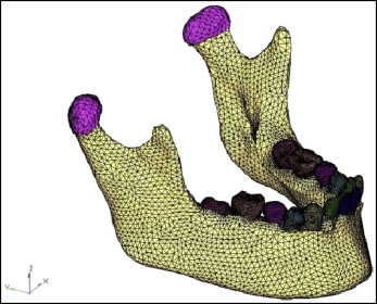
This study was designed to evaluate stress pattern distributions in different regions of the mandible with the Forsus appliance using the FEM. A 15-year-old girl with a typical Class II Division 1 malocclusion with an overjet of 11 mm was selected. Her chief complaint was an unpleasant appearance and backwardly positioned mandibular front teeth. After a clinical examination, the patient was planned to be treated with a fixed functional appliance, the Forsus. She had a skeletal Class II relationship with an almost normal maxilla, a retrognathic mandible, a positive visual treatment objective, an abnormal musculature, and a favorable growth pattern. All pretreatment records were taken for the patient including study models, photographs, CBCT scans, and interocclusal biting force recordings. The Forsus was planned to be given to the patient. Informed consent was obtained from the patient’s parents for her to participate in the study. The DICOM images of the mandible, TMJ, and associated structures were generated using CBCT scans to construct the mesh diagram ( Fig 1 ) for the finite element analysis with Mimics software (version 8.11; Materialise HQ, Leuven, Belgium) and HyperWorks software (version 9.0; Altair Engineering, Huntsville, Ala).
Full bonding and banding of the maxillary and mandibular arches was done using a 0.022-in MBT (Mclaughlin Bennett Trevisi) prescription. After leveling and alignment, the arches were U-shaped but in a Class II relationship. When the rectangular wire stage reached 0.019 × 0.025-in stainless steel, the Forsus appliance was used in single-step advancement. The attachment of the appliance was at the canine and premolar interface. The horizontal force values were calculated with a Dontrix gauge (American Orthodontics, Sheboygan, Wis). The vertical forces were recorded with a custom-made pressure sensor by placing the sensor in the molar region.
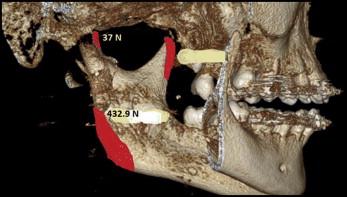
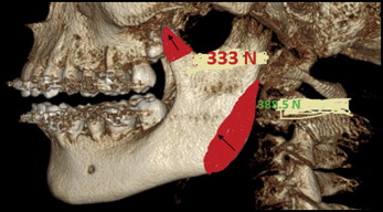
The muscles also exert forces on the mandible. Therefore, it is necessary to calculate the musculature forces for the assessment of the stress patterns on the mandible. The muscle areas were constructed by taking references from books of anatomy; however, interocclusal bite force recordings are specific for each patient. Muscle force in maximum intercuspation was calculated by multiplying the physiologic cross-sectional areas of the each masticatory muscle by 0.37 × 10² N. For the masseter, the calculated muscle force was 388.5 N; for the lateral pterygoid, it was 37 N; for the medial pterygoid, it was 432.9 N; and for the temporalis, it was 333 N, as shown in Figures 2 and 3 and Table I , as per the chart. The duration of treatment was 1 year 8 months.
| Muscle | PCS (cm 2 ) | Force (N) |
|---|---|---|
| Masseter | 10.5 | 388.5 |
| Temporalis | 9 | 333 |
| Medial pterygoid | 11.7 | 432.9 |
| Lateral pterygoid | 1.0 | 37 |
For the finite element model construction, a CBCT scan of the tooth and the mandible was taken into the Mimics software. Surface data of the metal casting and the mandible were generated using Solid Edge 2004 software (Siemens, Plano, Tex). From the 3D image of the CBCT, a mesh diagram was generated using the HyperWorks software. Finite element models were constructed from the DICOM images of slices 1 mm thick generated by the DICOM software. The assembled finite element model of the mandible was imported into Ansys software (version 12.1; Canonsburg, Pa) for analysis. The material properties assigned were Young’s modulus (or modulus of elasticity) and the Poisson ratio.
A vertical biting force of 111.55 N was applied in the molar region, and a horizontal force of 1948.24 N was seen distal to the canine in the horizontal direction. The model was restricted at the outer part of the skull at its most posterosuperior edges. This allowed the visualization of deformation and stress generation in the mandible.
Results
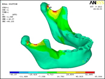
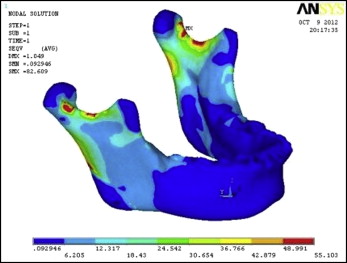
The results showed changes in terms of von Mises stresses and principal stresses. The total number of nodes was 462542, along with total elements numbering 92972. The color changes in terms of areas of maximum and minimum stresses were seen after the material properties were assigned. Red shows the maximum principal stress region, which is mainly tensile stress, and blue shows the minimum principal stress region, which is compressive stress. The results of this FEM analysis showed the areas of tension and compression in the mandible and associated structures.
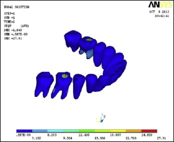
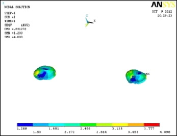
The results were calculated in terms of von Mises and principal stresses in the following regions: cortical bone, teeth, and condylar head.
In the resting stage of the mandible, the highest von Mises stresses were 55.103 MPa in the cortical bone ( Fig 4 ), 27.91 MPa in the teeth ( Fig 5 ), and 4.098 MPa in the condyle ( Fig 6 ).
The maximum principal stresses were 65.066 MPa in the cortical bone ( Fig 7 ), 20.96 MPa in the teeth ( Fig 8 ), and 4.117 MPa in the condyle ( Fig 9 ).