4
Endodontic Instruments and Canal Preparation Techniques
Laurence Jordan1,2,3, Francois Bronnec4, and Pierre Machtou5
1 Faculty of Dentistry, Paris University, Paris, France
2 Chimie ParisTech, PSL Research University, Paris, France
3 Rothschild Hospital AP‐HP, Paris, France
4 Private practice, Paris, France
5 UFR d’Odontologie, Paris Diderot University, Paris, France
4.1 Classification and Components of Endodontic Instruments
The aim of shaping is to create space for irrigant delivery in order to clean and disinfect the root canal system, and then for the placement of filling materials. Dedicated endodontic instruments have been manufactured for this purpose. The main problem encountered during shaping is the production of dentine debris, potentially leading to procedural mishaps. This chapter restricts itself to root canal shaping instruments and concepts. Table 4.1 shows a classification of shaping instruments based on ISO 3630‐5 [1], whilst Table 4.2 provides a timeline of the key dates in their development.
Table 4.1 Classification of shaping and cleaning instruments, based on ISO 3630‐5.
| Group | Specification | Type |
|---|---|---|
| 1 | Instruments for hand use | Barbed broaches, K‐files, H‐files |
| 2 | Engine‐driven – latch | Gates Glidden, Peezo drills |
| 3 | Engine‐driven – NiTi | Profile, ProTaper, Race |
| 4 | Engine‐driven – adapting to canal anatomy | SAF, XP‐Shaper/Finisher |
| 5 | Engine‐driven – reciprocating | Wave one, Reciproc |
| 6 | Sonic and ultrasonic |
Table 4.2 Timeline of the development of different generations of root canal shaping instruments.
| Date | Development | Details |
|---|---|---|
| 1904 | K‐Files, Reamers | Kerr’s development of the first endodontic instruments |
| 1959 | Standardization | |
| 1976 | Specification No. 28 | American Dental Association |
| 1988 | NiTi hand files | |
| 1991 | NiTi rotary | Passive radial lands, fixed tapers, single cross‐section |
| 1999–2001 | NiTi rotary | Active cutting tips, variable tapers, alternating cutting edges |
| 2007 | Thermal treatment | M Wire |
| 2008 | Generation 2 thermal | Twisted files |
|
2010–2018 |
Further NiTi development |
Changing cross‐section Reciprocation: WaveOne, Reciproc Structure change: SAF 2rd generation thermal treatment: CM (Coltene), Blue/Gold (Dentsply) Electric discharge machining (Coltene) Shape Memory (FKG) |
4.1.1 Brief History
From the second half of the nineteenth century, coarse instruments were created from piano wires in order to allow the removal of tissue remnants from the root canals. But in 1904, Kerr Manufacturing Company (Romulus, MI) manufactured what can be considered the first true endodontic instruments: the K‐type files (K‐files) and K‐type reamers (K‐reamers). A third type of root canal instrument is the H‐file, shaped like a wood screw and developed in 1940 by the Swedish company Sendoline in collaboration with the Swedish doctor Gustav Hedström. For years, files and reamers were manufactured in carbon steel and numbered from one to six, where each consecutive number was bigger than the preceding one. However, each company had its own way of producing the instruments, and there was no correlation between the different brands.
In 1955, Ingle called for the standardization of endodontic instruments [2], and he officially proposed the idea at the Second Conference of Endodontics held in Philadelphia in 1958 [3]. This standardization set specific dimensions for the tip (D1) and the top of the cutting portion (D2) (Figure 4.1). From the start, despite the reluctance of most other companies, the Swiss brand Maillefer embraced this project, inventing and manufacturing the first testing machines and quickly becoming the market leader. In 1961, the publication of Ingle’s seminal article, ‘A Standardized Endodontic Technique Utilizing Newly Designed Instruments and Filling Materials’ [4] was a turning point in the endodontics field. Ingle advocated replacing corrodible carbon steel with stainless steel, refined the standardization of instruments with the addition of a 0.08 file and of larger ones from 110 to 140, and implemented a colour‐coding system. A new standardized technique was proposed, thanks to the matching of the new standardized shaping instruments and filling materials. It is interesting to note that at that time, more attention was paid to filling than to effective cleaning and disinfection.

Figure 4.1 Ingle’s first standardization proposal.
Source: Ingle, J.I., Bakland, L.K., Baumgartner, J.C. Ingle’s Endodontics, 6th ed., chapter 26 C: Svec, T.A.: Instruments for cleaning and shaping, p. 821, 2008, PMPH USA, New Haven, Connecticut, USA.
In 1976, the Council of Dental Materials and Devices of the American Dental Association (ADA) approved the specification No. 28 [5] for endodontic files and reamers. In this specification were included Hedström files (No. 58), rasps and barbed broaches (No. 63), probes, applicators, condensers, and spreaders (No. 71). The materials used were carbon and stainless steel. Details regarding dimensions, sampling, inspection, and test procedures were given; these included diameter, taper, tip length, resistance to fracture, stiffness, and resistance to corrosion. Later, a group of experts from Fédération Dentaire Internationale (FDI), the World Health Organization (WHO), and the ADA created a committee as part of the International Organization for Standardization (ISO) to elaborate international norms based on the ADA’s initial work. Both ADA/ANSI (American National Standards Institute) specification No. 28 and ISO norms are updated on a regular five‐year basis. Thus, work is in progress on root canal shaping instruments for the ISO 3630‐1; 2019 specification Dentistry – Endodontic Instruments – Part 1 [5], specifying general requirements and tests methods for endodontic instruments and covering general size designations, tolerances for all design features, colour coding, packaging, and other details [6].
At the end of the 1980s, a promising idea was developed to substitute stainless steel with nickel–titanium (NiTi) alloy in the manufacture of endodontic hand files [7]. These files were supposed to be three times more flexible than their counterparts in stainless steel, and also to be more resistant to torsion [8]. But they turned out to cut much less and to have a tendency to break without warning. It was later realized that, due to their flexibility, the traditional filing motion was a drawback, as was the standardized technique of placing all files sequentially at the working length, which promoted a taper‐lock effect. However, it has since become possible to use them as engine‐driven instruments, making them more efficient and increasing their taper.
The Quantec and Profile, both featuring radial lands, are good examples of the 1990s era; notably, the Profile system developed by B. Johnson was the first mechanized system to advocate a pure crown‐down technique. In 2001, the innovative and patented ProTaper system was designed with sharp edges; this was the first to feature a working portion with variable (i.e. increasing and decreasing) tapers.
Some years later, it became clear that the only way to further improve the behaviour of these instruments was to work on the properties of the NiTi alloy [9]. Thus, in 2007, M‐Wire, the first NiTi heat treatment, significantly increased both flexibility and resistance to cyclic fatigue [10]. This was followed by the launch of the Twisted files [11], with a specific heat treatment used to identify the R Phase allowing them to be twisted instead of being ground. Since 2010, several more technological advances have emerged: a new shaping technique using reciprocation with only one instrument (WaveOne and Reciproc, Dentsply Sirona) [12], a self‐adjusting file (SAF, ReDent) with an innovative structure [13], and new NiTi alloys – CM wire (Coltene) [14], Blue and Gold heat treatments (Dentsply) [15], Electrical Discharge Machining (Coltene) [16], and, most recently, NiTi shape memory by FKG (XP Finisher and XP Shaper) [17]. For a review of the new thermomechanically treated NiTi alloys, see Zupanc et al. [18].
4.1.2 Alloys
4.1.2.1 Carbon Steel versus Stainless Steel
Steel is an alloy made of iron and carbon. Carbon steel was the first alloy used to manufacture K‐files and K‐reamers. Compared to stainless steel, it has a higher carbon content (usually up to 2.1% of its weight), which makes it stronger and harder. Its main shortcoming is it susceptibility to corrosion: it may rust and corrode when exposed to moisture, even moisture vapour in the air. Therefore, it cannot be autoclaved and is prone to rust in contact with sodium hypochlorite. It is also less ductile than stainless steel [19].
Nowadays, the majority of hand instruments are manufactured from stainless steel. Stainless‐steel instruments have greater resistance to breakage but less resistance to torque, and therefore tend to become deformed under stress [20]. Gates Glidden and Peeso drills are also manufactured from it.
Stainless steel has a high chromium content, which forms an invisible layer on the steel that prevents corrosion and staining. The chromium layer provides the material’s shiny aspect. Austenitic stainless steel is the largest family of stainless steel. Within the 300 series, type 304, which contains 18% chromium, 8–10% nickel, and 0.12% carbon, is mainly used for machining surgical instruments.
4.1.2.2 Nickel–Titanium
NiTi has been shown to be the alloy of choice for the manufacture of engine‐driven instruments, although some hand instruments are also made from it. It was first developed between 1959 and 1963 by William Buehler, a mechanical engineer at the United States Naval Ordnance Laboratory, and commercialized under the trade name Nitinol (which stood for ‘NiTi Naval Ordnance Laboratory’). This invention was not related to dentistry, as Buehler was looking for intermetallic compounds for the nose cone of a below‐the‐surface missile. He serendipitously discovered NiTi’s shape‐memory properties [21].
In 1972, the orthodontist George Andreasen [22] was the first to introduce NiTi into dentistry, and in 1988, Harmeet Walia [8] thought to use it to substitute stainless steel in endodontic hand instruments. The NiTi alloy composition used in endodontics is close to equiatomic: around 55 wt% Ni and 45 wt% Ti [7]. Since this discovery, these alloys have been used in many different fields: the automotive industry, the aerospace industry, and the medical device industry – particularly in cardiac and orthopaedic surgery [23].
4.1.3 Manufacture and Standardization
K‐files and reamers are made from a raw stainless‐steel wire which is ground into a 0.02 tapered square, triangular, or rhomboid blank. Locked on one end, the wire is then twisted counter‐clockwise to transform the edges of the blank into multiple cutting edges. In contrast, Hedström files are micro‐ground from a round stainless‐steel blank. Likewise, all NiTi instruments, whether hand‐operated or engine‐driven, are ground because they cannot be twisted due to the alloy’s superelasticity.
4.1.3.1 Standardization of Stainless‐Steel Instruments
According to Ingle [4], standardization implies (Figure 4.2):
- A uniform length of the active portion for all instruments from diameter D1 at 1 mm from the tip to diameter D2 at 16 mm.
- Numbering using the metric system to determine instrument size at D1, with a 0.05 mm increase per instrument from size 15 to 60 and a 0.10 mm increase from size 60 to 110. Sizes 0.08 and 0.06 and 110–150 were later added, along with a colour coding.
- A uniform 0.02 taper of the active portion, providing a 0.32 diameter increase at D2.
- A tolerance limit of ±0.02 mm for each diameter on the active portion.
- Colour coding: white, yellow, red, blue, green, and black from size 15 to 40, then repeating for subsequent instruments. The colours grey and pink were later added for sizes 0.08 and 0.06.

Figure 4.2 Standardization of endodontic instruments: sizing, numbering, and colour‐coding.

Figure 4.3 Tip modification.
- Standard lengths: 21, 25, and 31 mm.
Two modifications from Ingle’s initial proposal have since been implemented [6]:
- An additional measurement at D3, 3 mm from the tip (D1).
- Specification of the shape of the pyramidal tip: for standard instruments, the angulation of the tip is 75 ± 15° (Figure 4.3).
The status of the standardization of endodontic instruments has been investigated [24], and it was found that the dimensions of all files tested were within tolerance limits according to the ISO 3630‐1 specification [5]. In 1992, at the second International Federation of Endodontic Associations (IFEA) meeting in Paris, France, Schilder proposed the Profile Serie 29.02 hand files (Tulsa Dental), featuring a constant 29% increase between tip diameters. Instead of the 0.05 classical arithmetical tip size progression between standardized instruments, a geometrical progression provides a gradual increase in tip diameter, resulting in more instruments in small sizes, where they are most needed, and fewer in large ones.
4.1.3.2 Design of Endodontic Instruments: Terms and Definitions
A number of terms and definitions exist pertaining to the design of endodontic instruments. According to the third ISO 3630‐1; 2019 specification for Dentistry – Endodontic Instruments – Part 1 [5], general terms and definitions include (Figure 4.4):
- Standard instrument: An endodontic instrument having a uniform taper of 0.02 mm/mm length of the working part throughout the range of available sizes.
- Taper instrument: An endodontic instrument whose size is determined by the tip size and which has a uniform taper of the working part other than 0.02 mm/mm length.
- Nontaper instrument: An endodontic instrument with a cylindrical shape along its long axis.
- Non‐uniform (variable) taper instrument: An endodontic instrument with more than one taper along its working part.
- Shape instrument: An endodontic instrument with a contoured working part with a continuously varying profile.
- Tip: The part of an instrument intended as its point, the shape of which is at the discretion of the manufacturer.
- Working part: The part of an instrument with a cutting surface.

Figure 4.4 Instrument components.
Source: Courtesy Dentsply Sirona/Maillefer.

Figure 4.5 Cores.
Source: Courtesy Kerr Endo and Dentsply Sirona/Maillefer.
- Shaft: The part of an instrument between the handle or shank and the working part.
- Shank: The part of a rotary, oscillating, or reciprocating instrument designed to fit into the chuck of a handpiece.
- Operative part: The part of an instrument running from the tip to the handle or shank. Endodontic instruments are available in 21, 25, and 31 mm lengths.
Other definitions have been proposed [25] for the other components of an endodontic instrument:
- Core: The cylindrical central part of the file, the circumference of which is outlined and bordered by the depth of the flutes (Figure 4.5).
- Flute: The groove in the working surface of an instrument used to collect debris (soft tissue and dentine chips removed from the canal walls). Its depth, width, and surface aspect can vary according to the particular instrument (Figure 4.6).

Figure 4.6 Flute, edge, pitch, and helix angle.
Source: Courtesy Dentsply Sirona/Maillefer.
- Land: The peripheral portion of a rotary instrument, kept flat and smooth in order to centre the instrument in the canal space. Its planning action limits operator aggressiveness and provides peripheral resistance to the instrument (Figure 4.7).
- Cutting or leading edge or blade: The area with the greatest diameter that follows the groove (Figure 4.8).
- Pitch: The distance between a point on the leading edge and the corresponding point on the adjacent leading edge along the working surface. The smaller the pitch, the tighter the spirals and the greater the helix angle. Most files have a variable pitch that changes along the active surface (Figure 4.6).
- Helix angle: The angle formed by the cutting edge (the blade) and the long axis of the file. It helps augur debris from the flutes. The helix angle can be fixed or can change along the active portion; in the latter case, we speak of a ‘variable pitch’ (Figure 4.6).
- Rake angle: The angle formed by the leading edge and the radius of the file when the file is cut perpendicular to its long axis (Figure 4.7).
- Cutting angle (or effective rake angle): The angle formed from the cutting edge (leading edge) and the radius of the file when the file is cut perpendicular to the cutting edge. It is the best indication of the cutting ability of a file. It can be positive, neutral or negative (Figure 4.7).
- Tip design: The pyramidal distal end of the active part of a file. A pyramidal tip provides excellent cutting efficiency but may be too aggressive (Figure 4.8) [26]. Tips have been described as cutting, noncutting, or semicutting, but no clear distinction exists between the three. In 1985, in a seminal article on the balanced‐force technique, Roane et al. [27] proposed a modification of the tip for the purpose of eliminating the transition angle between it and the first blade (Figure 4.8), thereby avoiding canal ledging and transportation. A comparison of three different hand techniques and one mechanized technique demonstrated that canal preparation with a modified tip was significantly better than that using a traditional (unmodified) tip [28].

Figure 4.7 Radial land, rake, and cutting angles.
Source: Courtesy Dentsply Sirona/Maillefer.

Figure 4.8 Active tip (ProTaper Retreatment D1) and non‐active tip (ProTaper F3).
Source: Courtesy Dentsply Sirona/Maillefer.
4.1.3.3 Physical Properties of Endodontic Instruments: Terms and Definitions
A number of definitions also exist for the physical properties of endodontic instruments:
- Stress: The resisting force (expressed in N/mm2) per unit area of a material against deformation when external force is applied on it.
- Tensile strength: The capacity of a material or structure to withstand loads tending to elongate it.
- Yield strength: The stress which a material can withstand without permanent deformation.
- Strain: The change of original dimension (deformation) of a material under stress or load.
- Elastic limit: The greatest stress that an elastic solid can sustain without undergoing permanent deformation.
- Plastic deformation: The state of permanent deformation that pertains when a load is removed that exceeds a material’s elastic limit.
- Plastic limit: The point at which a material reaches the maximum plastic deformation and breaks (the breaking point).
- Superelasticity: An elastic (reversible) response to an applied stress, caused by a phase transformation between the austenitic and martensitic phases of a crystal. It is exhibited in shape‐memory alloys.
- Shape memory alloys (SMAs): A class of alloys than can recover apparent permanent strains when heated above a certain temperature.
4.1.4 Cleaning and Shaping Instruments
Cleaning and shaping instruments are divided into six groups according to their material of manufacture, mode of action, and shape (Table 4.1).
4.1.4.1 Group 1: Instruments for Hand Use (K‐Files, H‐Files, Barbed Broaches, Rasps)
4.1.4.1.1 K‐Files (ANSI/ADA Specification No. 28)
Stainless‐steel K‐files (Figure 4.9) are the most commonly used instruments for root canal shaping [20]. Conventionally, they are manufactured by twisting a 0.02 taper square stainless‐steel wire, but from sizes 30–140, a triangular cross‐section is generally used for better flexibility and cutting efficiency. This action creates tight and almost parallel cutting flutes; such a short pitch gives the instruments both strength and flexibility. Indeed, small‐sized K‐files resist buckling and therefore are considered the best instruments for penetration and initial negotiation of narrow canals [29, 30]. The most widely taught technique for scouting canals involves using a watch‐winding movement. The inward pressure of this motion has a tendency to block canals, and care should be taken to use a light touch with frequent irrigation. For canal negotiation, a watch‐winding/pull motion allowing a more careful apical progression should be preferred. West advocated precurving a small K‐file and letting it follow the canal pathway with a very light touch to the first light resistance [31]. At this stage, an envelope of motion (i.e. a 360° rotation) on withdrawal of the file is implemented to cut canal interferences [32]. On reinsertion, the file usually moves passively deeper.

Figure 4.9 K‐files.
Source: Courtesy Dentsply Sirona/Maillefer, Sybron Endo/Kerr, VDW.
For canal shaping, K‐files are mainly used with a rasping action and a push/pull motion. This in‐and‐out motion cuts debris from the canal walls, which can become packed in front of the instrument, leading to canal blockage. In large canals, a circumferential filing motion is usually advocated. K‐files can also be used with a reaming motion but, due to their negative rake angle, they are less efficient than reamers [33]. In this situation, care should be taken not to lock the file, because a counter‐clockwise rotation to unlock it again increases the risk of a quick instrument fracture [34].
The K‐file square cross‐section has been modified into a triangular one on Flexofiles (Dentsply‐Sirona/Maillefer) and a rhomboid one on K‐Flex (Sybron Endo/Kerr Dental) (Figure 4.9). Both are more flexible and have a better cutting efficiency. The obtuse angles of the rhomboid cross‐section of K‐Flex allow space for auguring debris, whilst the Batt tip of Flexofiles makes them well suited for the balanced‐force technique [35]. Flexicut files (VDW) are similar to Flexofiles.
The K Flexofile‐Golden Medium file series features intermediate sizes, providing a more gradual increase between instruments – especially smaller ones. With a triangular cross‐section and a Batt tip, they represent an alternative to the Profile Serie 29.02 (Tulsa Dental) mentioned previously. They are available in assorted packs of sizes 12–37 at 21, 25, and 31 mm. Dentsply Sirona/Maillefer offers stainless‐steel instruments in sterile blisters (Ready Steel Range) and with an ergonomic and comfortable silicone handle (Senseus Range).
C+ Files (Dentsply Sirona/Maillefer) are dedicated instruments for the location of canal orifices and negotiation of calcified canals. They are available in ISO sizes 06, 08, 10, and 15 with a pyramidal tip and a 4% taper on the last apical 3 mm, which provides an increased resistance to buckling [29, 30], and a 0.02 taper on the rest of the active portion. Well‐polished C+ Files are very aggressive instruments; their use should be restricted to retreatment cases.
Senseus Profinders are stainless‐steel K‐files featuring a decreasing taper .02 from the tip to the end of the active part 0.01. They are intended to be used during initial scouting of narrow root canals. They have an ergonomic silicone handle for finger comfort and a 65° tip, and are available in two lengths (21 and 25 mm) and three tip diameters (10, 13, and 15 mm).
C Pilot files (VDW) (Figure 4.9) are the best suited instruments for initial negotiation of narrow canals. They are regular K‐files which have undergone a specific hardening process to make them more resistant to buckling [30]. They are available in sizes 06, 08, 12.5, and 15 and three lengths (19, 21, and 25 mm), with measuring marks at 18, 19, 20, and 22 mm. The C‐Files (Dentsply Sirona/Maillefer) are similar to C‐Pilot files but are available only in 06, 08, and 10 sizes, without length marks.
Micro Openers (Dentsply‐Maillefer) (Figure 4.9) are stainless‐steel K‐files bent at 200° and connected to a long silicone handle. They are available in ISO sizes 10/04, 10/06, and 15/04 and are designed to be used under microscope vision control without finger obstruction to help locate and penetrate hidden or calcified canals.
4.1.4.1.2 K‐Reamers (ANSI/ADA Specification No. 28)
Stainless‐steel reamers (Figure 4.10) have a triangular cross‐section with sharp edges. Their manufacturing process is the same as that for K‐files, but with much less twists of the blank. This creates fewer spirals (approximately half as many as with a file), and hence a longer pitch and shorter helix angle: 20° compared to 40° for K‐files. Reamers are used with a reaming action to cut dentine (i.e. penetration to get in contact with the canal walls), a one‐quarter to one‐half rotation clockwise to engage the dentine, and then cutting on withdrawal [20]. A different mode of use is described in Schilder’s serial shaping technique, where precurved reamers were used on withdrawal in a series of recapitulations in order to create tapered canal preparations [32].
4.1.4.1.3 Hedström Files (ANSI/ADA Specification No. 58)
H‐files (Figure 4.10) have a single‐helix teardrop cross‐sectional shape [36]. They look like wood crews and are micromilled from a stainless‐steel round 0.02 taper wire. This blank rotates on a lathe machine that cuts a continuous spiral along its length. As a result, the core of an H‐file is much smaller that its external diameter, making it a fragile instrument. Due to their positive rake angle, H‐files are very effective in traction with pull strokes [33], but they should never be rotated at the risk of being locked and fractured (Figures 4.7 and 4.10). The Safety Hedström (Sybron Endo/Kerr, Romulus, MI, USA) proposed by Buchanan is a modification of the conventional H‐file. It has a flattened edge design with a noncutting, safe‐ended tip to help prevent ledging and stripping of the furcal region in curved and flat root canals.

Figure 4.10 K‐reamer and H‐files.
Source: Courtesy Dentsply Sirona/Maillefer.
Micro‐debriders (Dentsply‐Maillefer) have a 16 mm‐long working portion on a 200° bent H‐type file with a long silicone handle (Figure 4.10). They are available in sizes 20/0.02 and 30/0.02. Like micro‐openers, they are intended to be used under the microscope to help remove pulpal residues and remnants of paste or filling materials in retreatment cases, employing a pulling or circumferential action.
4.1.4.1.4 Machined K‐Type and H‐Type Files
The Flex‐R file (Miltex) is a machined stainless‐steel K‐file with a modified rounded tip intended to be used with the balanced‐force technique (Figure 4.11). The transition angle between the tip and the first blade is removed to reduce the risk of canal transportation [28]. On the active portion, the flutes have less depth in small sizes, in order to give more strength and more depth in the larger ones so as to improve flexibility.

Figure 4.11 Flex‐R files (Miltex), with their rounded patented tips.
Source: Reproduced from Ingle, J.I., Bakland, L.K., Baumgartner, J.C. Ingle’s Endodontics, 6th ed., chapter 26 C: Svec, T.A.: Instruments for cleaning and shaping, p. 821, 2008, BC Decker Inc., Hamilton, Ontario; Nitiflex file and Unifile file (Courtesy Dentsply Sirona/Maillefer).
MMC and MME (Micro Mega‐Coltene) are machined stainless‐steel K‐files and H‐files mainly dedicated to initial canal negotiation and subsequent enlargement.
Nitiflex or Sureflex files (Dentsply‐Maillefer) are NiTi machined K‐type files available from sizes 15 to 60 in 21 and 25 mm lengths. The special core geometry and cross‐section change progressively throughout the range of sizes, giving Nitiflex/SureFlex files their unique linear flexibility, which is practically constant throughout the range. The special alloy, special design, and special machining procedures give them outstanding long‐term sharpness fatigue and fatigue strength [37]. The large sizes are well suited for the balanced‐force technique [38].
The Unifile (DentsplySirona/Maillefer), first designed by McSpadden, was the first modification of H‐files. It is a double H‐file design available in 21 and 25 mm lengths and sizes 10–80 following the ISO standards. It is machined with the same grinding process as H‐files, but the flutes are less deep and the core is more important. It is a robust instrument that can be used with either pull strokes or a reaming action. Mounted on the Giromatic handpiece, the Dynatrak system is a mechanized version [25].
The S‐file (Sendoline) has an S cross‐section with double edges, giving it excellent cutting efficiency. Unlike the Unifile, the S‐file has a thin cylindrical core, resulting from an increasing depth of the flutes along the active portion. It can be used with either a rasping or a reaming action. There is a NiTi version named the NiTi S‐file.
4.1.4.1.5 Barbed Broaches and Rasps (ANSI/ADA Specification No. 63)
Barbed broaches (Figure 4.12) represent the oldest endodontic instruments, manufactured as early as the mid‐nineteenth century. They are made from a nontapered round blank of soft steel. A chisel is used to cut barbs at a definite angle along the long axis, which are then elevated. They serve mainly to extirpate the pulp tissue, but should be used carefully. They must never be used in curved or narrow canals, and only in the coronal two‐thirds of straight and large ones. They are first rotated to engage the pulp and then pulled out in order to remove it in one piece. They may also be used to remove cotton pellets or paper points. Rasps, or ‘rat tail files’, are no longer used today. They were historically employed to enlarge the root canal, applying a longitudinal rasping action to the walls. Compared to barbed broaches, their barbs are shorter and blunter.
4.1.4.2 Group 2: Engine‐Driven Latch‐Type Instruments
The various instrument types in this group are shown in Figure 4.12. These include Gates Glidden drills and Peeso reamers, which are run at slow speed.
Gates Glidden drills are safe side‐cutting instruments. They have an American football‐shaped cutting head with a U‐shaped cross‐section and radial lands mounted on a long, smooth, and flexible shaft attached to a latch‐type shank. Six instruments numbered from 1 to 6 with sizes 0.5, 0.7, 0.9, 1.1, 1.3, and 1.5 mm, respectively, are available in 32 or 28 mm length. They are used at slow speed (between 800 and 1.200 rpm), mainly to relocate canal orifices and create straight‐line access to the root canal. They should only be used in the straight portion of curved canals, and always on the outstroke. Another indication is the removal of gutta‐percha in retreatment cases. A safety feature breaks the shaft of the drill close to the shank when too much force is applied or in case of a poor angle of incidence to the root canal. They can be used in a step‐back fashion from small to big or in a crown‐down approach from big to small.

Figure 4.12 Barbed broach, Gates Glidden drill, and Peeso drill.
Source: Courtesy Dentsply Sirona/Maillefer.
Compared to Gates Glidden drills, Peeso drills or reamers have a long side‐cutting portion but the same cross‐section and the same safe, noncutting tip. They are available in six sizes of 0.7, 0.9, 1.1, 1.3, 1.5, and 1.7 mm and are mainly used for post‐space preparation.
4.1.4.3 Group 3: Engine‐Driven NiTi Rotary Instruments
These instruments are shown in Figures 4.13–4.15. Only those with some innovative features will be described here. Thanks to the introduction of NiTi alloys, the early 1990s saw the rebirth of mechanized instrumentation in endodontics. The first NiTi rotary instruments were the Quantec and ProFile systems. Launched by McSpadden, the Quantec system was the first to feature a 25/0.06, 17 mm‐long orifice opener and a series of NiTi files with different tip sizes and tapers. Unfortunately, at that time, the mode of use advocated a conventional shaping technique, with the placement of all instruments (from small to large) at the working length (see sequence in Figure 4.13, Figure 4.14). In contrast, W.B. Johnson’s Profile system featured a pure crown‐down technique and fewer instruments.

Figure 4.13 Dentsply Sirona/Maillefer systems.
4.1.4.3.1 Profile .04 .06 Taper Series (Densply Sirona/Maillefer)
Introduced in 1994, Profile instruments quickly became a reference in NiTi shaping instrumentation (Figure 4.13). Their main characteristic is a U‐shape cross‐section with radial lands. This type of cross‐section gives the file excellent flexibility, and the radial lands are supposed to increase the peripheral resistance, maintain the file centred in the canal, and decrease the screwing effect. Due to the radial lands, the instruments work with a planing action. Available with Orifice Shapers (OSs) in sizes 20–80 and with tapers of 5–8%, a crown‐down sequence with short pecking actions is advocated: one OS in the coronal portion of the canal, Profile 06 in the middle, and ProFile 04 and 02 in the apical region.
4.1.4.3.2 Quantec System (Sybron Endo/Kerr)
This system offers a wide range of tapers and tip sizes (Figure 4.14). The cross‐section has a double‐helical flute design with large radial lands and a relief area behind the blade to reduce friction. A slightly positive cutting angle provides efficiency. As already described, the Quantec system was initially launched with a traditional sequence, which was later stage substituted by a crown‐down one.
4.1.4.3.3 K3 NiTi Rotary Endo File System (Sybron Endo/Kerr)
This system was introduced in 2002 (Figure 4.14). Unlike Quantec files, the K3 system has a three‐blade cross‐section with positive cutting angle and land reliefs behind the blades. Tapers from 0.12 to 0.02 are used with a crown‐down technique.
4.1.4.3.4 Lightspeed System
Developed by Senia in the early 1990s, the Lightspeed System has a unique design that looks like a Gates Glidden drill. A very short active portion (0.25–2 mm in length) with a noncutting tip has a U‐shaped cross‐section and is followed by a long, parallel‐sided nonactive flexible shaft. A big range of instruments from size 20 to 160 makes the shaping procedure time‐consuming and tedious. The advocated speed of 750–2500 rpm is considerably higher than that of other rotary system. The Lightspeed instruments are well suited to gauging apical foramen size.
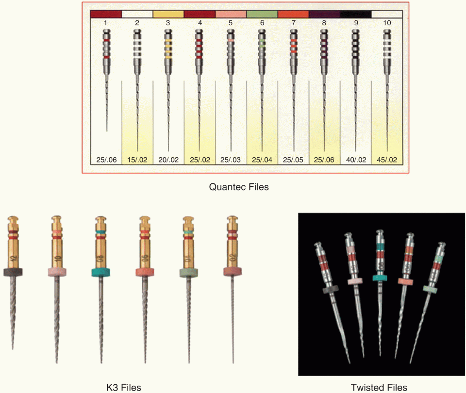
Figure 4.14 Sybron Endo/Kerr systems.
4.1.4.3.5 GT File Rotary System (DentsplySirona/Maillefer)
This system, developed by Buchanan, was very innovative when introduced on to the market in 1996. It features four instruments with 0.04, 0.06, 0.08, and 0.10 tapers, a constant tip size of 20, and a variable length of the active portion: short on the biggest file and increasing regularly towards the smallest. It is interesting to note that the maximum flute diameter (MFD) was the same (1 mm) on all instruments, making the GT system the first to maximize dentine preservation in the coronal third of the root canal. GT files were used with a straightforward crown‐down technique. In 2007, alongside the initial Series 20, the ProSystem GT file was manufactured in M‐wire and supplemented by the addition of a 30 Series, a 40 Series, and three accessory files. A GT hand file series is also available, which can be used in a reverse balanced‐force technique.
4.1.4.3.6 ProTaper System (DentsplySirona/Maillefer)
Due to its innovative features, the ProTaper System has been the leading product on the market since its introduction in 2001. It was the first system to implement cutting edges on NiTi instruments and to feature dedicated files for shaping and finishing, with variable progressive and regressive tapers on their working portion. Whatever the clinical situation, the shaping sequence remained the same, with a reduced number of files. In 2006, minor changes occurred in the ProTaper Universal system with the addition of two finishing files (F4 and F5) and a modification of the initial triangular convex cross‐section to improve flexibility on finishers F3, F4, and F5. Hand ProTaper files featuring the six instruments from the initial set are available as well as three retreatment rotary files: D1, D2, and D3. In 2015, a gold alloy replaced the original NiTi. Manual plastic handles can be clipped on to the rotary files so they can be used as hand instruments.
4.1.4.3.7 Race (FKG)
Race instruments (Figure 4.15) are machined with a triangular cross‐section and alternative cutting edges to eliminate the screwing effect. They are electropolished to improve resistance to fatigue and corrosion, and their tip is rounded for safety. A limitation of this system is its large number of files, with several complex sequences that must be selected between according to the clinical case.

Figure 4.15 FKG Race system.
Source: © FKG Dentaire SA, all rights reserved.
4.1.4.3.8 Twisted File (Sybron/Endo‐Kerr, Romulus, MI, USA)
These files (Figure 4.14) are not ground but twisted, as their name suggests. Through a complex heating and cooling process, the R Phase – the intermediate phase between austenite and martensite – is identified, allowing the file to be twisted in a soft state. A second complex heating and cooling process then brings it back to austenite. Compared to other NiTi files, the twisted files are more flexible and more resistant to cyclic fatigue and torsion [11], but they are still too soft.
4.1.4.3.9 Pathfiles (DentsplySirona/Maillefer)
These files are pathfinding NiTi rotary instruments used to create a sufficient and indispensable glide path prior to NiTi rotary shaping. They are 0.02 taper instruments with progressive tip sizes 0.13, 0.16, and 0.19. Today, all NiTi systems offer their own pathfinding instruments, sometimes with two or three files. Dentsply Sirona/Maillefer was the first company to launch a pathfile in the form of the Proglider, a single glide‐path instrument in M‐wire with progressive tapers on the working portion. The same option was adopted on the WaveOneGold Glider, for use before reciprocation shaping.
4.1.4.3.10 Heat‐Treated Files: M‐Wire, CM‐Wire, Blue and Gold Wire
At the end of the 2000s, after testing, combining, and implementing all possible design parameters on endodontic NiTi files with the aim of creating better instruments, it became apparent that the only way to improve their behaviour was to exploit the properties of the NiTi alloy. In 2008, Dentsply carried out the first heat treatment of the raw material prior to machining, giving the M‐wire [10]. The second generation was the R phase treatment [39] of twisted files (see earlier). Finally, the third generation of thermal treatments was recently carried out in order to optimize the mechanical properties of NiTi (flexibility and resistance to cyclic fatigue), giving the CM‐wire [14], Blue wire [15], and Gold wire [40]. Hyflex EDM (Coltene) is manufactured from CM‐wire, but with an electrical‐discharge machining process [16] to improve resistance to fracture and provide a better cutting action. Unlike with CM‐wire, the Gold heat treatment is done after machining, with an increase of the Af temperature to provide higher flexibility and resistance to cyclic fatigue whilst maintaining torsional strength. For a literature review on the new thermomechanically treated alloys, see Zupanc et al. [18].
4.1.4.4 Group 4: Engine‐Driven Instruments that Adapt Themselves to the Root Canal Anatomy
These instruments are shown in Figure 4.16. They include the self‐adjusting file (SAF), XP Shaper, and XP Finisher.
4.1.4.4.1 Self‐Adjusting File (ReDent NOVA)
The SAF is different from all other available endodontic shaping instruments. It is a hollow cylinder (i.e. without a central core) made of a fine peripheral NiTi lattice that can be compressed during use [13]. It has an asymetrical tip and is available in 1.5 and 2.0 mm diameters. The 1.5 mm‐diameter file may be compressed to the dimensions of a size‐20 K‐file, and the 2.0 mm one to the dimensions of a size‐35 K‐file. The file is attached to a rotary and vibrating handpiece connected to a pump that delivers irrigant. The solution flows through the hollow file, providing true intracanal irrigation. The SAF is not a cutting instrument but has an abrading action. Extensively studied, it may be suited for large canals but has shown limitations in narrow ones, where a glide path must be created with a size‐20 K‐file minimum.

Figure 4.16 SAF system, XP Shaper, and XP Finishers.
Source: ReDent Nova; © FKG Dentaire SA, all rights reserved.
4.1.4.4.2 XP Shaper and XP Finisher (FKG)
These are made of Max Wire, another proprietary thermomechanically treated NiTi alloy. They are the only NiTi endodontic instruments whose use is based on the NiTi shape‐memory property.
The XP Finisher is a single‐use instrument with 0 taper and a 25 or 30 tip size. Straight and soft in the martensitic phase at room temperature, it expands and becomes curved and stiff at body temperature when moving to the austenitic phase. The XP Endo Finisher ø 25 is efficient at the end of the shaping step in agitating irrigants, and the XP Finisher ø 30 in retreatment cases in removing remnants of filling materials [41]; it is used at 1.000 rpm and 1 N/cm torque.
The XP Shaper is a one‐file shaping instrument with a 1% taper and a 30 tip size [42]. Like the XP Finisher, it works on the same shape‐memory principle [43]. It can reach a 30/04 minimum taper at body temperature. The recommended speed is 1000 rpm with 1 N/cm torque.
4.1.4.5 Group 5: Engine‐Driven Reciprocating Instruments
Stay updated, free dental videos. Join our Telegram channel
VIDEdental - Online dental courses


