Introduction
Miniplates are the treatment of choice for complex orthodontic and orthopedic problems. However, they require surgical placement and removal, and complications such as infection and mobility can occur. The aim of this finite element analysis was to investigate the effects of a newly designed miniplate platform to elevate the miniplate above the gingiva.
Methods
A bone block was modeled in 3 dimensions, and 2 N of force was applied on miniplates in 2 scenarios. In scenario 1, the miniplate was fixed with 2 miniscrews on both ends; in scenario 2, miniplate platforms were first seated on the cortical bone surface with their spikes fully penetrating, and then the miniplate was fixed on top with 2 miniscrews.
Results
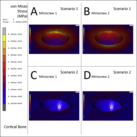
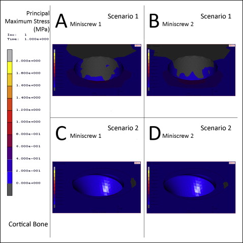
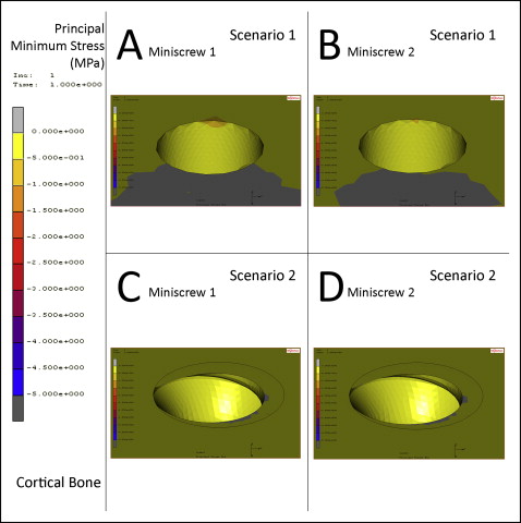
The highest von Mises stress on the cortical bone decreased from 0.5 to 0.3 MPa when miniplate platforms were used. In scenario 2, the principal maximum stresses on the cortical bone around the miniscrews decreased from 0.42 and 0.48 MPa to 0.20 and 0.22 MPa, and the principal minimum stresses decreased from −0.45 and −0.48 MPa to −0.01 MPa.
Conclusions
Miniplate platforms used to elevate the miniplate lowered the stresses generated on cortical bone around the miniscrews by distributing the stresses on the cortical bone surface. Patients can clean the miniplate more readily because it is elevated above the soft tissues. Placing the miniplate platforms requires only removing the gingiva with a punch, and their removal does not require flap surgery.
Highlights
- •
Miniplates can be elevated over the gingiva with a miniplate platform (MPP).
- •
Elevating the miniplate reduces stresses generated on the cortical bone.
- •
The MPP makes it easier to keep the miniplate clean.
- •
Elevating the miniplate may reduce complications and improve success rates.
- •
MPPs can be placed with only a gingival punch and removed without flap surgery.
A temporary anchorage device is temporarily fixed to bone to enhance orthodontic anchorage either by supporting the teeth of the reactive unit or by obviating the need for the reactive unit altogether, and it is subsequently removed after use.
Kanomi used miniscrews for mandibular incisor intrusion and inspired many researchers to give more attention to skeletal anchorage in orthodontics. Although some studies suggested that miniscrews have predictable and stable results, some others found complications such as pain, irritation, soft tissue inflammation, peri-implantitis, and loosening of screws. Miyawaki et al stated that miniscrews had a success rate of 83.9%, and the authors of most studies found success rates over 80%. If a miniscrew loosens, it will not regain stability and will probably need to be removed and replaced.
Miniplates have been used for treatment of fractures; after their clinical success in orthodontic practice, they have fulfilled the need for a more stable temporary anchorage device for complex orthodontic treatments. Miniplates may provide more secure anchorage when higher forces are needed. Cornelis et al made a survey to evaluate patients’ and orthodontists’ perceptions of miniplates during orthodontic treatment and reported good acceptance from both groups.
Miniplate failure rates have been reported to be over 7% in previous studies. Inflammation of the tissues around the miniplates can require miniplate removal. Choi et al stated that miniplates might be more reliable tools for orthodontic anchorage if the rate of complications was reduced, possibly by changing the size of the appliance. Oral hygiene is another important factor for success because prevention of inflammation of the peri-implant tissues is a critical factor for miniplate success.
Different designs of platforms and spikes were introduced to increase the stability of miniscrews and miniplates, such as the washer, the mini-implant ring, and the spiky miniplate.
The aim of this finite element analysis study was to investigate the effects of a newly designed miniplate platform (MPP) used to elevate the miniplate above the gingiva.
Material and methods
Finite element analysis was used to evaluate the stress distributions in bone, miniscrews, miniplates, and MPPs.
Three-dimensional (3D) models of all instruments, tested in this study, were scanned with a 3D scanner (SCAN ST; Steinbichler, Plymouth, Mich). Marc software (version 2005; MSC Software, Newport Beach, Calif) was used to construct the 3D finite element models for preprocessing and modeling. All final solid meshes were constituted by tetrahedral elements with 4 nodes using the Marc software. Finite element analysis was also performed with this software. In scenario 1, 90801 nodes and 466144 elements were used; in scenario 2, 141442 nodes and 717998 elements were used. All bone, miniscrew, miniplate, and MPP elements were assumed to be isotropic, homogeneous, and linearly elastic. The elastic properties of the materials used in this study are shown in Table I . Bone models were fixed for displacement and rotation in the x-, y-, and z-axes on 5 surfaces, except for the surface of bone with the appliance. All appliances used in this study were made of grade 5 titanium (Ti-6Al-4V). Three-dimensional finite element models were prepared, and finite element analyses were processed with an Intel Pentium D Windows 7 Pro computer (CPU 2.60 GHz, 32 GB RAM) (Intel, Santa Clara, Calif).
| Young’s modulus (MPa) | Poisson’s ratio | |
|---|---|---|
| Cortical bone | 13.7 × 10 3 | 0.3 |
| Trabecular bone | 7.9 × 10 3 | 0.3 |
| Miniscrew | 105 × 10 3 | 0.33 |
| MPP | 105 × 10 3 | 0.33 |
| Miniplate | 105 × 10 3 | 0.33 |
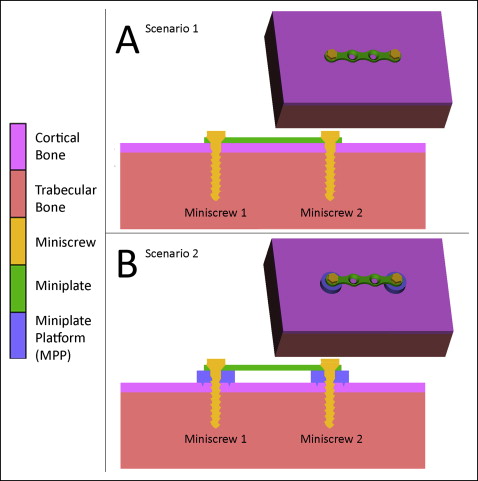
Supporting bone models were modeled consisting of cortical and trabecular bone. The modeled block of bone was a rectangular prism 48 mm wide, 30 mm deep, and 13.5 mm high. The upper 1.5-mm slice of the block was modeled as cortical bone, and the remaining 12 mm was modeled as trabecular bone ( Fig 1 ).
Cylindrical miniscrews, 1.7 mm in diameter and 8 mm in length (Ortho Easy; Forestadent, Pforzheim, Germany), were used ( Fig 2 , A ). In this study, we simulated osseointegrated miniscrews. For simulating such a condition, the miniscrews were fully bonded to the bone along their entire interface. Other than this, all interfaces, including bone-miniplate, miniscrew-miniplate, bone-MPP, MPP-miniplate, and MPP-miniscrew, were defined as face-to-face contacts.
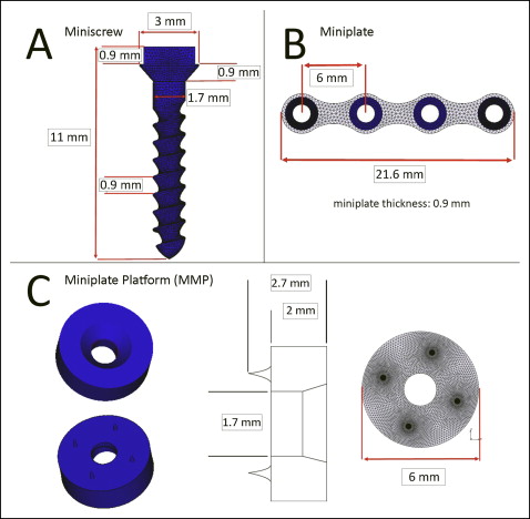
The surgical miniplate (Rita Leibinger, Neuhausen ob Eck, Germany) had a length of 21.6 mm and a height of 0.9 mm, and had 4 holes separated by 6 mm for miniscrew orientation ( Fig 2 , B ). The neck of the miniscrew and the holes of the miniplate were modeled with a perfect adaptation.
The MPP, which had 0.7-mm minispikes at the side that faced the cortical bone, was designed to elevate the miniplate above the gingiva. MPPs also increased the contact surface of the appliance with cortical bone, and the spikes of the MPPs fully penetrated into the cortical bone. This round appliance had a height of 2 mm, a diameter of 6 mm, and a hole in the middle that fit perfectly to the neck part of the miniscrew ( Fig 2 , C ).
Two scenarios were formed in our study. In scenario 1, miniplates were placed on the cortical bone and fixed with 2 miniscrews on both ends ( Fig 1 , A ). In scenario 2, miniplates were placed over the MPP ( Fig 1 , B ). Miniplates were therefore placed above the gingiva, whereas the lower surfaces of the MPPs were directly in contact with the cortical bone, with their spikes fully penetrating the bone, as if a gingival punch was used to remove the soft tissues before placement of the MPPs. The appliance was fixed with 2 miniscrews on both ends. The MPPs were designed to be 2 mm thick to elevate the miniplate over the gingiva.
The tip of the white arrow in Figure 3 , A , shows the point of force application of 2 N applied to the midpoint of the upper surface of the miniplate in a sagittal direction from left to right, parallel to the axis between the miniscrew middle points in both scenarios. This experimental setup was designed for easier evaluation and understanding of the stresses generated.
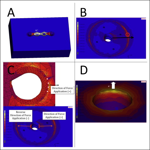
Von Mises stresses were measured and evaluated for titanium appliance elements; von Mises, principal maximum (compression), and principal minimum (tension) stresses were measured for cortical and trabecular bone. The miniscrew at the reverse direction of force application was called miniscrew 1, and the other miniscrew at the direction of force application was called miniscrew 2 ( Fig 1 ). Stresses on cortical bone around the neck of miniscrew were measured in the force application direction (+) and in the reverse direction of force application (−) ( Fig 3 , C ). For example, principal minimum stresses at the cortical bone around miniscrew 1 (−) signify the principal minimum stresses generated at the cortical bone around the miniscrew, which is at the reverse direction of force application.
Stresses were measured from several regions. The highest value measured shows the overall highest stress on the material, and the location of this value is presented in the results for each material. Four values around the miniscrews were measured: stresses around or at the necks of miniscrews 1 and 2 at the direction of force application (+) and the reverse direction of force application (−). Stresses generated at the outer edge and the cortical bone surface contacts were named the edge of the MPP, and stresses generated at the spike and cortical bone contacts were named spikes of the MPP.
When measuring the stresses generated around the necks of the miniscrews, the mean of the 4 nodes in contact with the miniscrews at the investigated regions was evaluated, since there was not necessarily a node intersecting the axis of force application direction. Figure 3 , C , shows 4 nodes selected for both the + and − directions. This measurement style was chosen to differentiate the highest value measured overall and the highest stresses generated at comparable regions. Overall highest stresses can be close to the direction of force application, but they may not be right on the axis; this makes it hard to evaluate and compare. Figure 3 , B , demonstrates how the highest stress on cortical bone around the miniscrew can be at a different location; therefore, the mean of the 4 neighboring nodes was selected to make the data comparable ( Fig 3 , C ). The white arrow in Figure 3 , D , shows the direction of force application on the close-up images. The white arrows in Figure 3 , A and D , represent 0°, meaning that the close-up images were rotated by 90° in a counterclockwise direction to see the 3D effect of the stresses around the miniscrews; the setup simplified the orientation.
Results
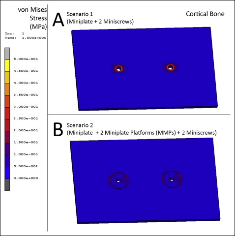
In scenario 1, the highest von Mises stress was measured as 0.5 MPa at the cortical bone surrounding the neck of miniscrew 2 ( Figs 4 , A , and 5 , A and B ). The highest principal maximum value on the cortical bone was 0.6 MPa located at the connection of miniscrew 2 and the cortical bone surface at the reverse direction of force application. The principal maximum stresses on the cortical bone around the necks of miniscrews 1 and 2 were measured as 0.42 and 0.48 MPa, respectively, at the reverse direction of force application ( Fig 6 , A and B ). The highest principal minimum value on the cortical bone was −0.6 MPa located at the connection of miniscrew 1 and the cortical bone surface at the direction of force application. The principal minimum stresses on the cortical bone around the necks of miniscrews 1 and 2 were measured as −0.48 and −0.45 MPa, respectively, at the direction of force application ( Fig 7 , A and B ) ( Table II ).
| Cortical bone | Von Mises (MPa) | Principal maximum (MPa) | Principal minimum (MPa) |
|---|---|---|---|
| Scenario 1 (miniplate + 2 miniscrews) | |||
| Highest value measured | 0.50 | 0.60 | −0.60 |
| Neck of miniscrew 1 (+) | 0.42 | 0.00 | −0.48 |
| Neck of miniscrew 1 (−) | 0.35 | 0.42 | 0.00 |
| Neck of miniscrew 2 (+) | 0.38 | 0.00 | −0.45 |
| Neck of miniscrew 2 (−) | 0.48 | 0.48 | 0.00 |
| Scenario 2 (miniplate + 2 MPPs + 2 miniscrews) | |||
| Highest value measured | 0.30 | 0.31 | −0.34 |
| Neck of miniscrew 1 (+) | 0.08 | 0.07 | 0.00 |
| Neck of miniscrew 1 (−) | 0.22 | 0.22 | −0.01 |
| Neck of miniscrew 2 (+) | 0.08 | 0.07 | 0.00 |
| Neck of miniscrew 2 (−) | 0.20 | 0.20 | −0.01 |
| Edge of MPP | 0.20 | 0.00 | −0.30 |
| Spikes of MPP | 0.10 | 0.90 | −0.10 |
In scenario 2, the highest von Mises stress was measured as 0.3 MPa at the surface of the cortical bone, in contact with the outer edge of the MPP, which is located at the direction of force and fixed with miniscrew 2 ( Figs 4 , B , and 5, C and D ). The highest principal maximum value on the cortical bone was 0.31 MPa located at the connection of miniscrew 1 and the cortical bone surface at the reverse direction of force application. The principal maximum stresses on the cortical bone around the necks of miniscrews 1 and 2 were measured as 0.22 and 0.20 MPa, respectively, at the reverse direction of force application ( Fig 6 , C and D ). The highest principal minimum value on the cortical bone was −0.34 MPa at the surface of the cortical bone, in contact with the outer edge of the MPP, which is located at the direction of force and fixed with miniscrew 2. The principal minimum stresses on the cortical bone around the necks of miniscrews 1 and 2 were measured as almost 0 MPa in both regions at the direction of force application ( Fig 7 , C and D ). The principal minimum stresses were located at the cortical bone surface touching the outer edge of the MPP, and the spikes of the MPP measured −0.3 and −0.1 MPa, respectively ( Table II ).
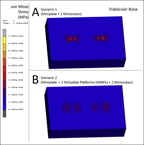
In scenario 1, the highest von Mises stress was measured as 0.06 MPa at the trabecular bone, where it was in contact with the cortical bone around miniscrew 2 ( Fig 8 , A ). The highest principal maximum value on the trabecular bone was 0.06 MPa located at the connection of miniscrew 2’s thread and trabecular bone at the reverse direction of force application. The principal maximum stresses on the cortical bone around miniscrews 1 and 2 were measured as 0.02 MPa in both regions at the reverse direction of force application. The highest principal minimum value on the trabecular bone was −0.04 MPa located at the connection with the cortical bone around miniscrew 2 at the direction of force application. The principal minimum stresses on trabecular bone around miniscrews 1 and 2 were measured as almost 0 MPa in both regions at the direction of force application ( Table III ).
| Trabecular bone | Von Mises (MPa) | Principal maximum (MPa) | Principal minimum (MPa) |
|---|---|---|---|
| Scenario 1 (miniplate + 2 miniscrews) | |||
| Highest value measured | 0.06 | 0.06 | −0.06 |
| Around miniscrew 1 (+) | 0.04 | 0.00 | −0.04 |
| Around miniscrew 1 (−) | 0.03 | 0.02 | 0.00 |
| Around miniscrew 2 (+) | 0.04 | 0.00 | −0.05 |
| Around miniscrew 2 (−) | 0.02 | 0.02 | 0.00 |
| Scenario 2 (miniplate + 2 MPPs + 2 miniscrews) | |||
| Highest value measured | 0.03 | 0.03 | −0.04 |
| Around miniscrew 1 (+) | 0.01 | 0.00 | 0.00 |
| Around miniscrew 1 (−) | 0.02 | 0.02 | 0.00 |
| Around miniscrew 2 (+) | 0.01 | 0.00 | 0.00 |
| Around miniscrew 2 (−) | 0.02 | 0.02 | 0.00 |
Stay updated, free dental videos. Join our Telegram channel
VIDEdental - Online dental courses


