Introduction
Orthodontic treatment is an important part of dental health care in Europe: the percentages of the population undergoing therapy vary from 10% to 55%. Therefore, quantifying effective orthodontic loads is a challenging topic with regard to the predictability of tooth movements and the reduction of traumatic side effects.
Methods
A customized measuring platform was developed and used for detecting orthodontic forces in a range between 0.1 and 2 N. The system consists of 6 load cells, each equipped with 6 strain gauges. The tests were conducted on a 3-dimensional printed malocclused mouth model and on a plaster cast. Four types of superelastic ligation and 2 types of invisible aligners were tested to analyze, respectively, a malocclusion with a high maxillary canine, and the effects on the axial rotation of a maxillary central incisor with and without a divot in the invisible aligners.
Results
Optimal treatment forces are exerted by low-friction wires, especially if they are partially engaged. Moreover, by reducing the treatment force, there is less necessity of anchoring to surrounding teeth, thus decreasing the side effects. The efficacy of using invisible aligners with a divot was validated.
Conclusions
This platform allowed measurement, at the radicular level, of the resultant forces of orthodontic treatments performed with different orthodontic appliances. In addition to customizing and calibrating the therapy for each patient, this platform could be used to develop new specific instruments able to exert lower treatment forces, thus preventing irreversible damages.
Graphical abstract
Highlights
- •
A customized measuring platform for 3D orthodontic loads detection is proposed.
- •
The device is suitable for any kind of fixed orthodontic appliances.
- •
Two cases of malocclusion, treated with wire-brackets and an invisible aligner, were analyzed.
- •
Lowifriction wires exert optimal loads.
- •
Invisible aligners with a divot provided better rotation control.
- •
This platform can be used to train clinicians to exert lower loads and thus avoid irreversible damage.
The interest in understanding orthodontic tooth movements comes from the necessity to improve orthodontic treatment strategies and therefore each patient’s condition in terms of early diagnosis, reduction of risk of trauma at the dental and periodontal tissue levels, and reduction of pain. The therapeutic force-moment system is the origin of complex biologic processes that underlie bone remodeling and tooth movement. However, it is well known that all orthodontic procedures cause side effects in patients, including pain and major damage such as root resorption. The latter is an unavoidable and unpredictable consequence of orthodontic tooth movement that starts with inflammation and leads to the destruction of the tooth root structure; when it involves the dentin, it becomes irreparable. The resorption lacunae arise on the pressure side of the tooth after the application of nonbiologic forces. When these forces are not optimal, blood flow slows and subsequently stops because of the compression of the vessels; after that, the tissue undergoes ischemia that induces necrosis.
Hence, the risk of causing traumatic effects and its correlation with orthodontic therapy must be considered. Over the years, this link has long been discussed. Although some authors do not believe that there is a close connection between the magnitude of applied loads and traumatic side effects, recent investigations have shown how root resorption phenomena are related to high forces and moments. The loss of dental hard tissue was found to be higher in the pressure areas, thus highlighting the interrelationship between traumatic phenomena and therapeutic forces. It is therefore clear that controlling the orthodontic force-moment system, rather than relying on experience or intuitiveness, is paramount for therapeutic success.
To this end several attempts have been made, but only recently have researchers developed instruments for 3-dimensional (3D) in-vivo and in-vitro recording of orthodontic mechanical forces. Apparatuses equipped with commercial load cells acting on a mouth model and a microelectronic chip equipped with multipiezoresistive stress sensors mounted on the brackets or directly on the teeth can be found ( Table I ). Unfortunately, these systems have several limitations that hamper their clinical applications: long acquisition times, nonsimultaneous acquisition processes, and nonreal-time acquisitions. Certain instruments detect the measurements at a point different from that of force application (tooth root), and others rely on simulators of the mouth, thus preventing the analysis of crowding in real patients. Moreover, no attention has been paid to the design of a measuring instrument suitable for all kinds of orthodontic appliances.
| Measuring device | Teeth (n) | Degrees of freedom | Modality | Device |
|---|---|---|---|---|
| Piezoresistive stress sensors (Shi et al, 2012) | 1 | 3 | Resin tooth model | Invisible aligners |
| Industrial automation nano17 load cells (Badawi et al, 2009) | 14 | 6 | Aluminum cylinder tooth model | Wire-bracket complex |
| Smart brackets (Lapatki et al, 2007) | 1 | 6 | 3-bracket model/finite element method analysis | Wire-bracket complex |
| Precision industrial robot RX 60 and FTS nano 12-0.12 3D force-moment sensor (Fuck and Drescher, 2006) | 10 | 6 | Dental cast | Wire-bracket complex |
| Detachable brackets and 6 axis force-torque sensor (Friedrich et al, 1999) | 1 | 6 | Real teeth | Wire-bracket complex |
In this study, we aimed to exploit the innovative technology developed with a customized load cell to detect 3D orthodontic forces, exerted from a generic orthodontic device, in a more thorough way. Many patients can be analyzed with this device as a real mouth model (plaster cast or 3D printed model) to which the sensor can be interfaced and set up each time.
Material and methods
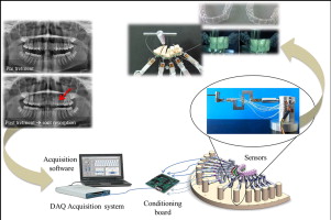
The customized load cell ( Fig 1 ) was designed in 3 parts that rigidly connect together with a variable size between 0.7 (when high sensitivity is required) and 10 mm. Six force sensors (strain gauges, Micro-Measurements; Vishay Precision Group, Wendell, NC) were bonded on the structure. Table II shows the mechanical forces read by each strain gauge according to the reference system shown in Figure 1 . The construction material of the sensor is ergal, an aluminum alloy with better mechanical properties than aluminum itself. The load cell interfaces with the tooth thanks to a dental flowable composite (Tetric EvoFlow; Ivoclar Vivadent, Amherst, NY). This material hardens quickly, thus allowing each tooth to be positioned in a few seconds and ensuring, at the same time, high stability. The load cells are connected to an electronic acquisition system that sends data to a computer. The acquisition software used was from NI LabVIEW (Austin, Tex), and the output data were processed with MATLAB software (MathWorks, Natick, Mass). The load cell was adjusted by applying known weights in the range of orthodontic loads.
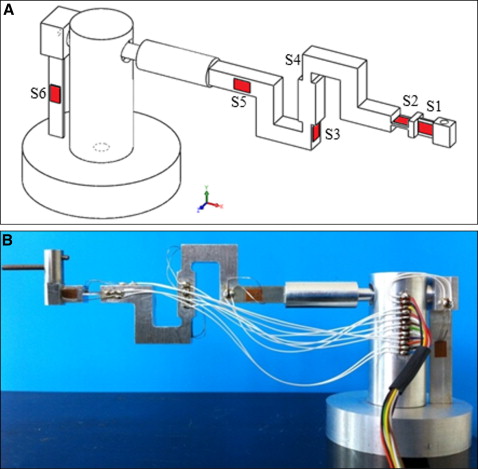
| Strain gauge | Mechanical force | Direction |
|---|---|---|
| S1 | M y | Rotation |
| S2 | M z | Torque |
| S3 | F x -F y | Lingual-buccal force and extrusion-intrusion force |
| S4 | F x -F y | Lingual-buccal force and extrusion-intrusion force |
| S5 | F z | Mesiodistal force |
| S6 | M x | Tip |
Two case studies are presented here: a malocclusion with a high maxillary canine treated with different superelastic wires, and the effects on the axial rotation of a maxillary central incisor with and without a divot in the invisible aligners.
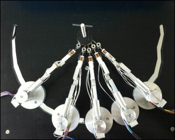
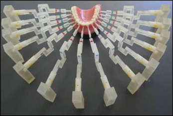
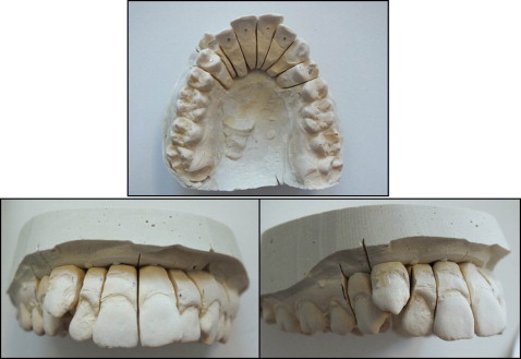
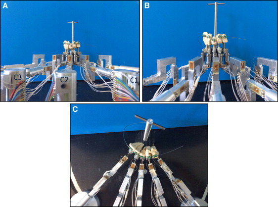
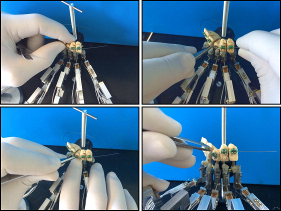
In the first case study, the complete orthodontic measuring platform was composed of 5 customized load cells connected to the patient’s malocclused plaster mouth. The 5 sensors were arranged on a drilled base that allowed for adjustments of their positions before the acquisition ( Fig 2 ). Theoretically, the load cells would number 14: 1 for each tooth in the dental arch ( Fig 3 ). The choice of using only 5 load cells lies in the type of malocclusion investigated: one with a high maxillary canine ( Fig 4 ). To this end, 3 active load cells measured the force-moment data on the maxillary right first premolar, maxillary right canine, and maxillary right lateral incisor ( Table III ). Two neutral load cells, in contact with the maxillary central incisor and the maxillary right second premolar, are needed to support these 2 teeth to simulate a real mouth where each tooth is affected by the forces of the neighboring teeth ( Fig 5 ). Each tooth of the plaster cast has a pin placed during casting. Once the model solidified, the clinician mounted the brackets (MIDI Diagonali MBT system; Leone, Florence, Italy; and SmartClip; 3M Unitek, Monrovia, Calif) with the MBT prescription on the involved teeth. Then the teeth were sectioned and set on the load cells with the Tetric EvoFlow dental composite, which links the pin of the tooth to 1 load cell, which in turn is bound in a steel cylinder. Finally, the dentist mounts the wire on the teeth ( Fig 6 ), after having blocked the load cells through a fixation system. This system ensures that loads do not act on the cells during the assembly phase. Four tests with superelastic wires (Leone) were conducted: 0.012-in nickel-titanium, 0.012-in nickel-titanium SmartClip (fully and partially engaged), 0.014-in nickel-titanium, and 0.016-in thermal nickel-titanium.
| Load cell | Tooth |
|---|---|
| C1 | Maxillary right first premolar |
| C2 | Maxillary right canine |
| C3 | Maxillary right lateral incisor |
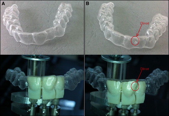
Usually, therapy with invisible aligners has little control over the rotation force. In the second case study, to better correct this moment force, an invisible aligner (ALL IN; Micerium, Avegno, Italy) with a divot corresponding to the tooth to be treated was used. In this analysis, the ability of the divot in controlling the rotation movement was verified. The invisible aligners exert a pure rotation force. The divot was placed according to the mapping proposed by orthodontic specialists in V7-L9 with a thickness of 1 mm. (V7-L9 is an acronym to indicate the position in which the divot was placed. V means vestibular and L means lateral [internal side]).
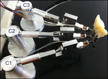
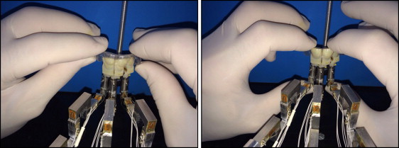
The orthodontic measuring platform is composed of 3 load cells in contact with the maxillary right lateral incisor, maxillary right central incisor, and maxillary left central incisor ( Table IV , Fig 7 ). The teeth are printed in 3 dimensions via a scan of the patient’s mouth. Three patients’ mouths were tested. Each configuration concerns the simulation of the treatment outcome from previous treatment steps (each lasting about 15 days). For each mouth, 3 types of aligners were used: one that does not exert mechanical forces on teeth but is needed for calibration, one that exerts treatment loads but does not have a divot on its surface, and one with a divot ( Fig 8 ). Once the 3 teeth per mouth were sectioned, they were interfaced to the load cell with the Tetric EvoFlow dental composite. Then, with aligner number 1, the right position of the load cells is reconstructed. The placement of the invisible aligner without a divot on the teeth is shown in Figure 9 .
| Load cell | Tooth |
|---|---|
| C1 | Maxillary right lateral incisor |
| C2 | Maxillary right central incisor |
| C3 | Maxillary left central incisor |
For both case studies, before starting to read the data, an acquisition with no load was made to calibrate the system on the initial conditions of each case.
Results
In the first case study, the mean values of the loads acting on the 3 teeth when treated with different superelastic ligations are given in Table V . The data are expressed in grams for the forces and grams per centimeter for the moments (obtained by multiplying the force with the corresponding lever arm: ie, the distance between the strain gauge and the tooth). The lever arm values were 2 cm for strain gauge S1, 1.2 cm for strain gauge S2, and 1 cm for strain gauge S6.
| Tooth | Sensors | 0.012 in | 0.012 in, SmartClip, partially engaged | 0.012 in, SmartClip, fully engaged | 0.014 in | 0.016 in, thermal |
|---|---|---|---|---|---|---|
| Premolar | C1 S1 Rotation | 57.8 gcm | 11.7 gcm | 34.04 gcm | 16.86 gcm | 60.9 gcm |
| C1 S2 torque | 80.17 gcm | 30.89 gcm | 114 gcm | 133.68 gcm | 127.92 gcm | |
| C1 S3-S4 F x | 35.5 g | 0 g | 2.5 g | 30 g | 58.4 g | |
| C1 S4-S3 F y | 50 g | 19.7 g | 22.6 g | 49.5 g | 97.8 g | |
| C1 S5 F z | 7.16 g | 0 g | 0 g | 13.7 g | 9.32 g | |
| C1 S6 tip | 4.95 gcm | 86.65 gcm | 197 gcm | 132.8 gcm | 134.4 gcm | |
| Canine | C2 S1 rotation | 50.46 gcm | 98.26 gcm | 128.28 gcm | 15.24 gcm | 45.58 gcm |
| C2 S2 torque | 112.49 gcm | 70.49 gcm | 6.85 gcm | 135.71 gcm | 142.93 gcm | |
| C2 S3-S4 F x | 72.6 g | 58.5 g | 89.2 g | 153.1 g | 137.5 g | |
| C2 S4-S3 F y | 35.2 g | 21.7 g | 26.7 g | 46.44 g | 44.24 g | |
| C2 S5 F z | 7.62 g | 9.6 g | 12.9 g | 22.07 g | 10.63 g | |
| C2 S6 tip | 8.76 gcm | 43.65 gcm | 66.42 gcm | 119.3 gcm | 140.3 gcm | |
| Incisor | C2 S1 rotation | 176.44 gcm | 6.2 gcm | 35.34 gcm | 104.02 gcm | 27.24 gcm |
| C2 S2 torque | 134.28 gcm | 63.84 gcm | 55.68 gcm | 179.16 gcm | 159.12 gcm | |
| C2 S3-S4 F x | 19.8 g | 0 g | 22 g | 91.8 g | 107.6 g | |
| C2 S4-S3 F y | 26.7 g | 13 g | 27.3 g | 66.5 g | 82.8 g | |
| C2 S5 F z | 3 g | 5.63 g | 7.23 g | 7 g | 6.65 g | |
| C2 S6 tip | 114.8 gcm | 65 gcm | 87.86 gcm | 38.90 gcm | 47.77 gcm |
Stay updated, free dental videos. Join our Telegram channel
VIDEdental - Online dental courses


