CHAPTER 3 Dynamics of Tip-Edge
From Rx-1 to the ‘Plus’ bracket
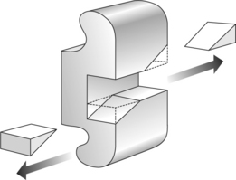
To start the story at its very beginning in 1986, the first Tip-Edge brackets came about by means of a metal saw. The best inventions are frequently the simplest. Dr Peter Kesling’s original aim was to make differential tooth movement possible within an edgewise type bracket face. The prototype Tip-Edge brackets were therefore derived from a single .022 inch straight-wire bracket merely by cutting away two diametrically opposed corners from the archwire slot (Fig. 3.1).1 This resulted in a bracket that enabled the crown to tip in a predetermined direction, whereas with an archwire of full vertical thickness, it would resist tipping in the reverse direction. This was a logical design, since the desired direction of tipping, in routine orthodontic cases, is easy to predict. In general, distal crown tipping is the way the bracketed teeth will naturally want to incline, the main exception being the second premolar in first premolar extraction cases, which will require to tip mesially into the extraction spaces. There are other rare exceptions to this rule, such as where anterior teeth are missing when, if not restoring the spaces, a canine may need to be moved mesially to simulate a lateral incisor, sometimes requiring a contralateral bracket.
Since its introduction, the Tip-Edge bracket (designated Rx-1) has more than proved itself clinically. It is demonstrably able to tackle difficult malocclusions with an ease of tooth movement, light anchorage and effective overbite reduction, which makes conventional ‘bodily movement mechanics’ look pedestrian by comparison. Of course, the technique has been progressively refined and improved, in the light of clinical experience, notably when it became able to exploit rectangular wire in an entirely new way (see Chapter 14). Simultaneous uptake of torque and tip, powered by auxiliaries, could now achieve a precision finish. It thus became a truly preadjusted appliance. Such developments along the line, however, were mainly confined to technique and archwire usage. Major developments to the bracket itself did not prove to be necessary. The Rx-1 bracket slot works well. Why, then, the arrival of the Plus bracket in 2003?
As will be understood in Chapter 14, each bracket requires an auxiliary in the final stage in order to deliver a three-dimensional root correction. With the Rx-1 bracket, this inevitably entailed fitting a Side-Winder spring to virtually every tooth, for the duration of the finishing phase. Clearly, this was seen as a disincentive to using Tip-Edge, particularly among edgewise and straight-wire orthodontists. Also, some of the advantages that Tip-Edge had originally enjoyed over straight-wire in the economy of archwires (normally only three in each arch per treatment) had been lost with the coming of the latest generation of nickel–titanium wires. These have been widely adopted in straight-wire techniques to simplify treatment progression, but without hitherto finding a place in Tip-Edge. Might not such advances in technology be able to streamline treatment with Tip-Edge also? Such was the thinking that initiated the development of Plus.
Unlike the Rx-1 brackets, which are manufactured by casting, Plus brackets are metal injection molded. They are also available in ceramic. This is also injection molded, producing a very smooth surface without the need for machining, which might weaken the ceramic. A bonded polymer base ensures safe debonding.
Cases treated with both the Rx-1 and Plus brackets are therefore presented in this book.
The bracket face
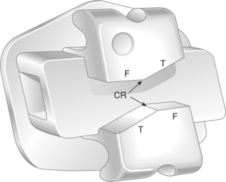
Tip-Edge brackets (Fig. 3.2) contain many features already familiar to the edgewise or straight-wire operator, including conventional tie wings, which accept standard elastomeric ligatures. Likewise, bracket identification is by small circular markers at the disto-gingival tie wings of the maxillary anterior brackets, and similarly placed triangular markings for the mandibular anteriors. (The orientation of premolar brackets depends on the desired direction of tipping and is dealt with in Chapter 6.)

Fig. 3.2 Tip-Edge Plus bracket. CR = central ridge, T = tip-limiting surfaces, F = finishing surfaces.
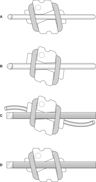
The basic sequence of Tip-Edge treatment is therefore illustrated, showing an upper right canine from its starting position (Fig. 3.3A). During the initial decrowding or overjet reduction, the crown will tip distally into a corrected Class I relationship. Since no root angulating forces are imparted, anchorage will be extremely light during this stage. In an extreme case, the amount of distal crown tip will be limited by the tip-limiting surface (Fig. 3.3B), so that excessive tipping is prevented. The tip-limiting surfaces are angled 25 degrees to the horizontal on canines, 20 degrees on all other bracketed teeth, although in clinical practice such maximum angles of tip will rarely be encountered. Once all crowns are correctly repositioned, a passive rectangular archwire is fitted and an auxiliary nickel–titanium archwire is threaded through the deep tunnels (Fig. 3.3C). This will distalize the root to its prescribed angulation, at which point the uprighting action of the auxiliary archwire will become self-limited by the approximation of the finishing surfaces above and below the main archwire (Fig. 3.3D).
The preadjusted finishing prescription contained within the Rx-1 bracket system is identical in principle to today’s straight-wire systems, with tip in the face, torque in the base. The values (Table 3.1) are particular to Tip-Edge (both Rx-1 and Plus). However, alongside the various prescriptions in common use today, they compare most closely to the Roth specification. It should perhaps be mentioned that TP Orthodontics have also produced a Siamese twin version of the Tip-Edge bracket in both .018 and .022 inch formats, perhaps in an attempt to identify more closely with conventional brackets. They are unlikely to appear in Plus format. In the author’s opinion, neither can be recommended. A/>
Stay updated, free dental videos. Join our Telegram channel

VIDEdental - Online dental courses


