Introduction
This clinical study was performed to evaluate the anteroposterior and vertical displacement patterns of the maxillary teeth in sliding mechanics depending on the position of interradicular miniscrews after the extraction of premolars.
Methods
Thirty-six women requiring maximum incisor retraction because of bialveolar protrusion were divided into 2 groups: group A (n = 18), miniscrew between the premolar and the molar, and group B (n = 18), miniscrew between the premolars. Cephalometric measurements for skeletal and dental changes were made before and after space closure.
Results
In both groups, significant incisor retraction with intrusion of the root apex was noted, with no significant change in the first molar position. Group B displayed significantly greater intrusion at both the incisal tip (1.59 ± 1.53 mm) and the root apex (2.89 ± 1.59 mm) than did group A. In spite of the mean reduction of the vertical skeletal measurements, we failed to find significant skeletal changes.
Conclusions
Miniscrews provided firm anchorage for anterior retraction. Selection of the placement site appeared to be an important determinant for the resultant displacement pattern of the incisor segment. Discriminative intrusion or retraction might be obtained via strategic miniscrew positioning.
Monocortical miniscrew-type temporary anchorage devices have become appliances of choice for securing anchorage in clinical orthodontics. The main orthodontic problems that demand maximum anchorage for premolar extraction include severe crowding and protrusion, which are frequent in many ethnic groups. Anterior retraction is performed with specific strategies that involve vertical control and specified tooth movement types, considering the patients’ preferences. Clinicians are frequently concerned about vertical control of the incisors when a patient has vertical esthetic problems—ie, a deepbite or a gummy smile. Although the clinical effectiveness of miniscrews as anchorage devices has already been shown elsewhere, the effects of varying placement sites on the pattern of anterior tooth movement has not been studied much.
Compared with others such as implants and onplants, a major strength of the miniscrew is the variety of placement sites that can be used. Several authors have demonstrated miniscrew placement at the interradicular space between the second premolar and the first molar for retraction of the anterior segment after premolar extraction. The subapical area is preferred for intrusion of the incisors. Selection of the placement site is based on the common sense that the amount of anteroposterior or vertical force vector might affect the displacement pattern of the segment. The “line of force” is thus determined by simply connecting the line between the miniscrew head and the attachment hooks on the wire, and it is obvious that varying miniscrew positions would create different force vectors. Considering the popularity of sliding mechanics with continuous wire, the following biomechanical characteristics need to be considered to better understand the mechanism of tooth movement in miniscrew sliding mechanics.
Unlike the reciprocal attraction between the anterior and posterior segments along the main archwire in conventional sliding mechanics, the elastic force from the miniscrew head does not primarily affect the posterior segment. Hence, it might not be necessary to put gable or compensatory bends in the archwire. A plain archwire would be adequate for the stabilization of the posterior segment in miniscrew sliding mechanics. Therefore, with a plain archwire, the line of force passing below the center of resistance of the anterior segment might lead to rotational movement of the incisor segment, possibly causing an increase in overbite. In contrast, since miniscrews placed in the alveolar bone normally have an intrusive component of force, the resultant incisor position is questioned.
Additionally, subsequent displacement of the posterior segment might follow the movement of the anterior segment because of the connection of the 2 segments along a continuous archwire.
In spite of ample clinical reports in the literature, investigations of the effect of miniscrew position on the movement pattern of the anterior and posterior segments are scarce, especially with regard to vertical effects. Due to the limited predictability of the biomechanical behavior of continuous wire on a theoretical basis, actual movement of the anterior and posterior segments needs to be investigated in clinical circumstances. The aims of this study were to compare the clinical effects of a single line of force from 2 miniscrew positions in patients with bialveolar protrusion and thus to provide useful clinical information on appropriate selection of placement sites for intentional control of retraction and intrusion in extraction patients.
Material and methods
The subjects were selected from the patients who visited the orthodontic departments at either Yonsei University Dental Hospital or Samsung Medical Center, Seoul, Korea, between 2004 and 2006, with the chief complaint of lip protrusion ( Table I ). Since the authors carried out an intention-to-treat analysis, all patients were included in the analysis regardless of treatment outcome, by an investigator (Y.J.K.) who had not been informed of the purpose of this study: (1) skeletal Class I or mild Class II patients when 4 premolars were indicated to be extracted because of protrusion, (2) interincisal angle smaller than 115°, (3) well-aligned maxillary and mandibular incisors with minimal crowding of less than 3 mm, (4) normal or moderately excessive overjet (2 mm <overject <6 mm), (5) permanent dentition with no missing or malformed tooth, and (6) cervical vertebrae maturation index of 6, indicating cessation of active growth, according to Franchi et al.
| Variable | Group A (n = 18) | Group B (n = 18) | Significance | ||
|---|---|---|---|---|---|
| Mean | SD | Mean | SD | ||
| Age at T1 (y) | 22.25 | 5.36 | 22.10 | 5.73 | NS |
| Duration of retraction (T1-T0) (mo) | 10.35 | 2.33 | 11.15 | 3.51 | NS |
| Overall treatment time (mo) | 22.35 | 5.53 | 24.32 | 7.03 | NS |
| Miniscrew–archwire distance (mm) | 8.21 | 1.61 | 8.30 | 1.95 | NS |
| Line of force-archwire angle (°) | 12.55 | 3.73 | 18.87 | 6.80 | ∗ |
A total of 36 women (mean age, 22.17 ± 5.54 years) who met above inclusion criteria were selected and then further divided into 2 groups depending on the miniscrew position as described below ( Table I ).
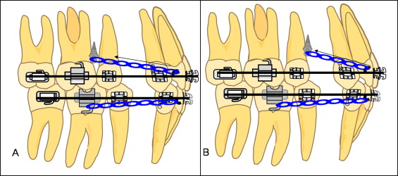
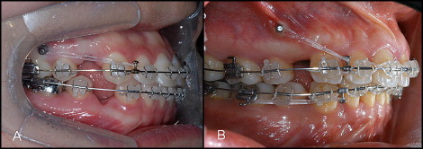
All patients were treated with preadjusted edgewise appliances with the Roth prescription (Tomy, Tokyo, Japan) and an 0.018 × 0.025-in slot. In the maxilla, all first and second molars were bonded with molar tubes instead of bands for accuracy of the cephalometric measurements. After the initial bonding, tapered miniscrews with either 1.8-mm diameter and 7.0-mm length of the thread part (Orlus No 18107; Ortholution, Seoul, Korea) or 2.5-mm diameter and 7.0-mm length (Orthoplant 2507T; BioMaterials Korea Inc, Seoul, Korea) were placed between the maxillary second premolar and the first molar in group A (n = 18), or between the first and second premolars in group B (n = 18), under infiltration anesthesia ( Fig 1 ). The miniscrews were placed only by 2 experienced operators (K.J.L. and S.H.K.). In the mandible, reciprocal attraction with elastic chains between the archwire hooks and either the first or second molar tube, depending on the molar relationship, was used. Plain 0.016 × 0.022-in stainless steel rectangular archwires were placed in both arches including the second molars. Short crimpable hooks (TP Orthodontics, LaPorte, Ind) or soldered hooks were attached distally to the lateral incisor ( Fig 2 ). A retraction force of 150 g was given by the elastic chains (Ormco, Glendora, Calif), and the chains were renewed every 4 weeks. In both groups, space closure was performed independently in each arch, and the use of intermaxillary elastics was avoided to eliminate possible extrusive effects on the anterior segment. After space closure, vertical up-and-down elastics in the posterior segment were used for final settling of the occlusion. Cephalometric films were taken before (T0) and after (T1) space closure so that the effects of the vertical elastics could be eliminated.


At T0 and T1, standardized digital lateral cephalograms were taken by using the Cranex3+ Ceph (Soredex, Milwaukee, Wis). V-Ceph software (version 3.5; Cybermed, Seoul, Korea) was used to obtain the cephalometric measurements. The radiographic magnification of the cephalograms was standardized at 100% actual size, with a 100-mm metal ruler image captured in the digital film as the reference.
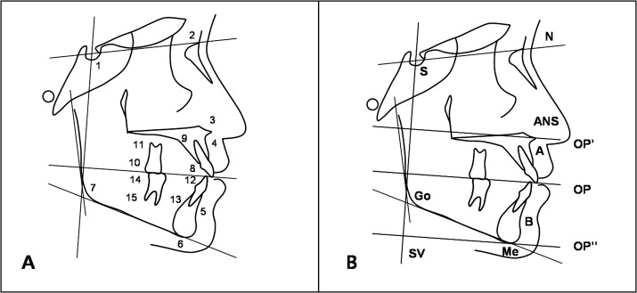
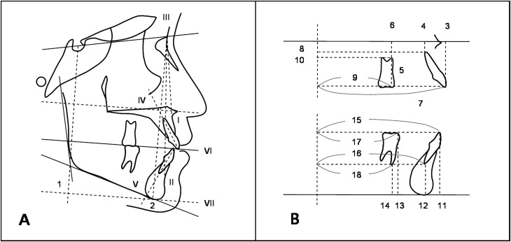
A reconstructed occlusal plane (OP) was made by rotating the palatal plane (PP) at ANS (OP′) by the initial OP-PP angle, and by rotating the mandibular plane (MP) at menton by the initial OP-MP angle (OP′′). A perpendicular line to the OP′ line passing sella (SV) was used as the vertical reference plane. The anteroposterior and vertical distances of the incisors and the first molars in each arch were measured. Cephalometric landmarks and planes, angular measurements, linear measurements, and abbreviations used in this study are summarized in Figures 3 and 4 .


Statistical analysis
All statistical analyses were performed with SPSS software (version 14.0; SPSS, Chicago, Ill). Cephalometric measurements were made with the V-Ceph software by an examiner who was unaware of the purpose of the study (T.H.C.). With a 2-week interval, all cephalometric digitizing and analyses were repeated by the same examiner. Intraexaminer reliability was assessed by paired samples t tests between the 2 sets of measurements, and no significant differences between them were found. Correlation between paired measurements was examined, with the highest coefficient for SNA (0.977) and the lowest for the SN-OP angle (0.912).
The mean and the standard deviation for each cephalometric variable were determined in each group. The Kolmogorov-Smirnov method was used to confirm the normal distribution of the measurements. A 2-tailed paired t test was then used to determine the significance of the treatment changes (T1-T0) in the groups. An unpaired t test determined the differences of the 2 groups between T0 and T1. Correlation coefficients between the amounts of retraction and other variables were also obtained. The statistical significance was determined at the 5% level of confidence.
Results
Of the 72 miniscrews placed in the 36 subjects, 4 miniscrews failed during retraction (2 in group A, 2 in group B), resulting in a 94.4% overall success rate. In the failure cases, retraction was transitionally discontinued for 2 to 3 months, and the miniscrews were replaced in the same interradicular area, with some clearance from the original site. None of the replaced miniscrews failed; hence, the failures were considered to have little influence on the results.
At T0, the 2 groups were similar in both the anteroposterior and vertical skeletal measurements. The mean SN-MP angle was larger in group B, but there was no statistical significance.
At the end of retraction, both groups had significant decreases in SNA and SNB, implicating possible alveolar bone remodeling around Points A and B according to the posterior movement of the incisors. The significant reduction in the ANB angle was attributed to the greater reduction in the SNA than in the SNB. The occlusal plane angle significantly increased during retraction in group A. No statistical significance was found between the 2 groups in any skeletal measurement ( Table II ).
| Variable | T0 | T1-T0 | ||||||||||
|---|---|---|---|---|---|---|---|---|---|---|---|---|
| Group A | Group B | Significance | Group A | Group B | Significance | |||||||
| Mean | SD | Mean | SD | Mean | SD | Significance | Mean | SD | Significance | |||
| SNA (°) | 81.72 | 4.01 | 81.33 | 3.23 | NS | −0.89 | 0.20 | † | −1.83 | 2.09 | ∗ | NS |
| SNB (°) | 77.55 | 3.52 | 75.99 | 2.78 | NS | −0.34 | 0.69 | ∗ | −0.83 | 1.02 | ∗ | NS |
| ANB (°) | 3.58 | 2.07 | 4.83 | 1.71 | NS | −0.55 | 0.94 | ∗ | −1.01 | 1.60 | ∗ | NS |
| SN-MP (°) | 36.41 | 5.55 | 39.66 | 5.50 | NS | −0.14 | 0.75 | NS | −0.35 | 0.94 | NS | NS |
| AFH (mm) | 130.62 | 6.13 | 132.80 | 3.72 | NS | −0.38 | 1.40 | NS | −0.68 | 1.33 | NS | NS |
| PFH (mm) | 83.67 | 6.03 | 82.73 | 5.51 | NS | 0.34 | 0.94 | NS | −0.03 | 0.75 | NS | NS |
| SN-OP (°) | 18.79 | 3.96 | 20.65 | 5.13 | NS | 1.36 | 1.25 | ∗ | 0.07 | 2.20 | NS | NS |
Before retraction, there was no significant difference in the dental measurements between the groups except for the maxillary incisor angle, which was greater in group B. Retraction of the incisors at both the incisal tip and the root apex in the maxilla and the mandible (U1t-SV, U1r-SV, L1t-SV, L1r-SV) was significant in both groups. Maxillary molar movement was not significant during retraction (U6t-SV, U6r-SV), whereas significant mesial displacement was noted in the mandible. Intrusion of the incisal tip (U1t-OP′) was significant in group B, and intrusion of the root apex was significant in both groups (U1r-OP′). The mandibular incisors displayed significant retraction in both groups but no significant vertical displacement. Overbite and overjet were reduced in both groups, with a significant change in overjet in group B ( Table III ).
| Variable | T0 | T1-T0 | ||||||||||
|---|---|---|---|---|---|---|---|---|---|---|---|---|
| Group A | Group B | Significance | Group A | Group B | Significance | |||||||
| Mean | SD | Mean | SD | Mean | SD | Significance | Mean | SD | Significance | |||
| U1t-SV (mm) | 91.78 | 6.44 | 93.25 | 5.60 | NS | −7.20 | 1.58 | † | −7.32 | 2.04 | † | NS |
| U1r-SV (mm) | 75.28 | 4.06 | 76.45 | 4.90 | NS | −2.66 | 1.45 | † | −3.20 | 2.91 | † | NS |
| U6t-SV (mm) | 55.41 | 3.90 | 57.01 | 4.60 | NS | 0.70 | 1.25 | NS | 0.80 | 1.41 | NS | NS |
| U6r-SV (mm) | 55.11 | 3.98 | 57.60 | 3.55 | NS | 0.45 | 1.58 | NS | 0.45 | 1.55 | NS | NS |
| L1t-SV (mm) | 86.45 | 5.39 | 88.24 | 5.84 | NS | −5.85 | 1.71 | † | −5.71 | 2.64 | † | NS |
| L1r-SV (mm) | 77.43 | 6.34 | 76.42 | 6.14 | NS | −1.85 | 1.39 | † | −1.94 | 1.77 | † | NS |
| L6t-SV (mm) | 58.08 | 4.25 | 60.34 | 4.44 | NS | 1.94 | 1.48 | ∗ | 2.01 | 1.85 | ∗ | NS |
| L6r-SV (mm) | 52.80 | 5.26 | 53.04 | 5.16 | NS | 2.04 | 1.67 | † | 2.09 | 2.58 | ∗ | NS |
| U1-PP (°) | 119.48 | 4.52 | 115.86 | 5.61 | ∗ | 9.89 | 5.18 | † | 10.74 | 6.09 | † | NS |
| IMPA (°) | 103.83 | 3.54 | 100.06 | 6.73 | NS | −10.18 | 5.29 | † | −7.42 | 7.84 | † | NS |
| U1t-OP′ (mm) | 30.92 | 2.36 | 31.33 | 2.47 | NS | 0.25 | 1.51 | NS | −1.59 | 1.53 | † | † |
| U1r-OP′ (mm) | 10.57 | 2.37 | 11.44 | 3.42 | NS | −1.80 | 1.45 | † | −2.89 | 1.59 | † | † |
| U6t-OP′ (mm) | 30.45 | 2.55 | 31.39 | 2.05 | NS | −0.24 | 0.78 | NS | −0.44 | 1.24 | NS | NS |
| U6r-OP′ (mm) | 12.07 | 2.78 | 13.35 | 2.89 | NS | −0.35 | 0.74 | NS | −0.55 | 1.45 | NS | NS |
| L1t-O′′ (mm) | 43.97 | 3.12 | 45.24 | 2.77 | NS | 0.34 | 1.06 | NS | 0.99 | 1.34 | NS | NS |
| L1r-O′′ (mm) | 24.78 | 2.29 | 24.88 | 1.99 | NS | −0.77 | 1.70 | NS | −0.45 | 1.54 | NS | NS |
| L6t-O′′ (mm) | 43.09 | 3.68 | 42.77 | 2.44 | NS | 0.35 | 1.27 | NS | 0.60 | 1.07 | NS | NS |
| L6r-O′′ (mm) | 24.15 | 2.31 | 23.77 | 2.55 | NS | 0.80 | 1.69 | NS | 0.95 | 1.44 | NS | NS |
| Overbite (mm) | 2.77 | 2.11 | 3.44 | 2.34 | NS | −0.67 | 1.74 | NS | −1.33 | 1.66 | NS | NS |
| Overjet (mm) | 3.66 | 2.54 | 4.36 | 2.77 | NS | −0.94 | 1.45 | NS | −1.98 | 2.03 | ∗ | NS |
Stay updated, free dental videos. Join our Telegram channel

VIDEdental - Online dental courses


