Fig. 5.1
Comparison of EQV magnitude within a cortical and b cancellous bones for both surgical approaches at different load locations
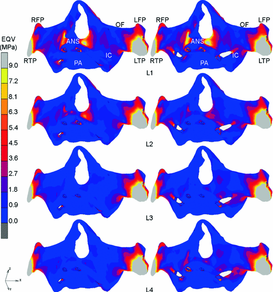
Fig. 5.2
Comparison of EQV distribution within cortical bone under L1 to L4 for the intrasinus and extramaxillary approach (left to right) as viewed from frontal (ANS Anterior nasal spine, IC Infrazygomatic crest, LFP Left frontal process, LTP Left temporal process, MSL Maxillary sinus lateral wall, OF Orbital floor, PA Palatal area, RFP Right frontal process, RTP Right temporal process)
This finding is in agreement with the works done by Bonnet et al. and Daas et al. who reported that higher stress was observed in the molar region as compared to other regions (canine and incisor) [1, 2]. The results of this numerical analysis also supported the concept of a class 3-Lever wherein a higher magnitude of forces is required to lift the weight as the force moves nearer to the fulcrum. In clinical situations, the force, fulcrum and weight are represented by occlusal forces, the temporomandibular joint and food, respectively.
5.1.2 Mechanical Stress Distribution Within the Framework
Again, the results of stress distribution within the framework indicated that posterior loads resulted in high stress magnitudes and concentration around the connection of framework-implants. As observed in intrasinus approach, the magnitude of EQV increased as loads moved posteriorly (158.00–294.27 MPa). This situation was also seen in extramaxillary approach where EQV magnitudes increased from 136.05 MPa up to 459.35 MPa (Fig. 5.3). The peak EQV value within the framework was recorded under L4, with extramaxillary approach being 36 % higher than intrasinus. In comparison, the framework in extramaxillary demonstrated higher values of EQV than that in intrasinus approach (12–36 %) under almost all loading locations except for L1 (being 14% lower).
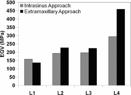
Fig. 5.3
Comparison of EQV magnitude within the framework for both surgical approaches
This outcome was parallel to the stress results obtained within the bodies of zygomatic implants wherein posterior loads were the major influencing factors. The load applied to the top surface of the framework in the molar region resulted in high stress concentration that could be due to resistance to high bending moments generated by the zygomatic implants. A balanced stress distribution was seen on the framework model when it was loaded anteriorly as shown in Fig. 5.4. A possible explanation for this observation is that there may be a progressive transfer of occlusal load from the load point to the surrounding conventional and zygomatic implants in the mesio-distal direction.
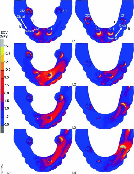
Fig. 5.4
Comparison of EQV distribution within the framework under L1 to L4 for the intrasinus and extramaxillary approach (left to right) as viewed from top axial (B Buccal, L Lingual)
In order to easily differentiate between the implant models, two sets of symbols were used. The first symbol denotes the types of implants: “ZI” for the zygomatic implant and “CI” for the conventional implant. The second symbol indicates the location of the implants: “1” and “2” symbolises the placement of the implant in the left (working side) and right side (non-working side) of the bone model, respectively.
5.1.3 Mechanical Stress Distribution Within the Implants
Within both zygomatic implants investigated, it appears that the 2nd molar load (L4) configuration led to the highest stress values in ZI1 for both intrasinus (64.8 MPa) and extramaxillary approaches (91.3 MPa) as illustrated in Figs. 5.5a, b. The high stresses were mainly concentrated at the abutment-implant connection and spread out towards the coronal and intermediate parts of the implant body on the bucco-lingual side. The apical part seemed to have a smaller EQV dispersion than the coronal part, and the stress concentration region became wider as the applied load moved posteriorly (Figs. 5.6, 5.7).
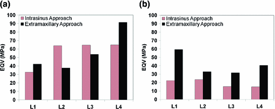
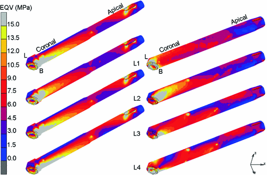
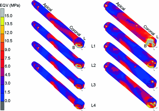
Fig. 5.5
Comparison of EQV magnitude within a ZI1 (working side) and b ZI2 (non-working side) for both surgical approaches
Fig. 5.6
Comparison of EQV distribution within ZI1 under L1 to L4 for the intrasinus and extramaxillary approach (left to right) as viewed from frontal
Fig. 5.7
Comparison of EQV distribution within ZI2 under L1 to L4 for the intrasinus and extramaxillary approach (left to right) as viewed from frontal
Stay updated, free dental videos. Join our Telegram channel
VIDEdental - Online dental courses


