Fig. 7.1
Bone-anchored RPE. No tooth attachment design. (a) Pre-expansion. (b) Post-expansion
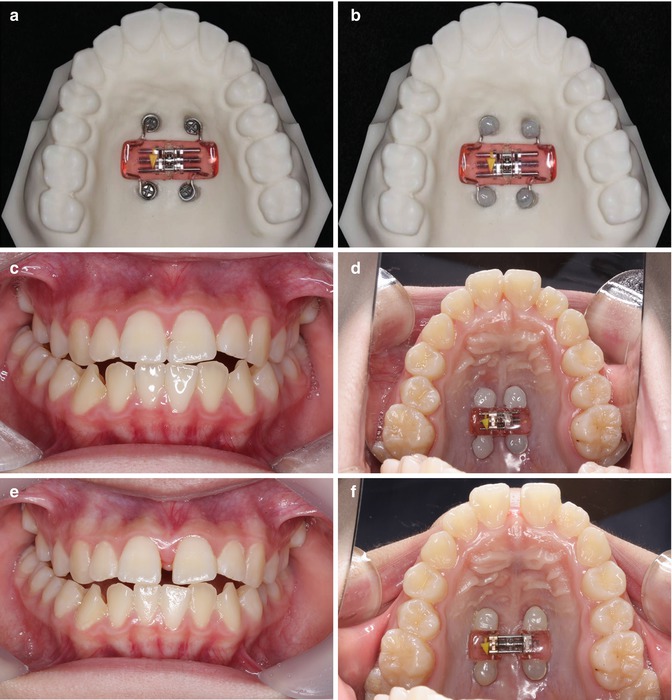
Fig. 7.2
No tooth attachment design (Courtesy of Dr. Yoon-Ah Kook, Dr. Seong-Hun Kim). (a) Bone-anchored RPE. (b) Bone-anchored RPE was secured with the flowable composite. (c) Frontal view of pre-expansion. (d) Occlusal view of pre-expansion. (e) Frontal view of post-expansion. (f) Occlusal view of post-expansion
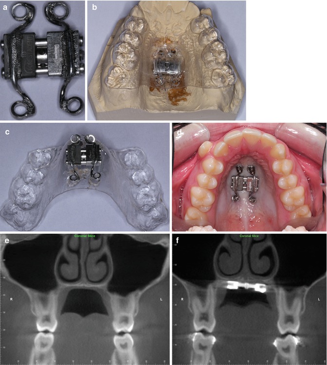
Fig. 7.3
No tooth attachment design. (a) Expansion screw. (b) Expansion screw with vacuum-formed template on the model. (c) Expansion screw with vacuum-formed template. (d) Expansion screw applied to a patient. (e) Coronal view of CBCT, pre-expansion. (f) Coronal view of CBCT, post-expansion. RPE screw was expanded by 6 mm, but intermolar distance was increased by 2.8 mm
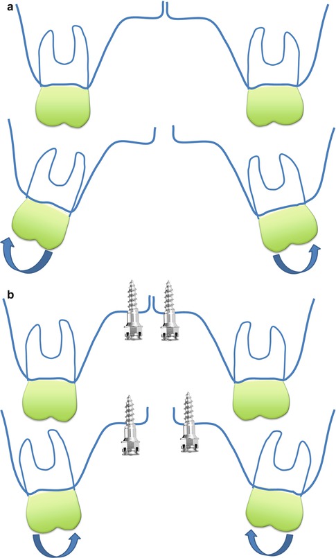
Fig. 7.4
Dentoalveolar response after RPE. (a) Buccal crown tipping with tooth-anchored RPE. (b) Palatal crown tipping with bone-anchored RPE
7.2 Supporting Wires Design
A Hyrax® expander was fabricated on a plaster cast marked with the locations for four or two miniscrew implants. Four metal rings were laser-welded to the expander screw. Stainless steel wires were extended to the lingual of the maxillary premolars and first molars to prevent palatal tipping. Four miniscrew implants were inserted in both palatal slopes using a template made with a vacuum-forming plastic (Fig. 7.5). If one side of the miniscrew implant is placed more gingivally than in the other side, then as the expansion progresses, the supporting wire on the same side can be embedded into the soft tissue, and this causes soft tissue irritation (Fig. 7.6).
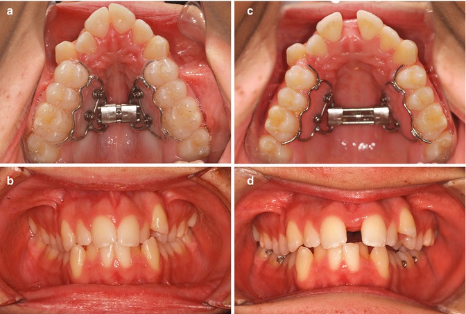
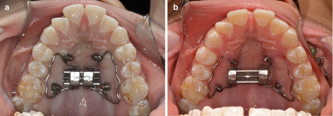
Fig. 7.5
Supporting wire design. (a) Occlusal view of pre-expansion. (b) Frontal view of pre-expansion. (c) Occlusal view of post-expansion. (d) Frontal view of post-expansion
Fig. 7.6
Supporting wire design problem. (a) Occlusal view of pre-expansion. (b) Occlusal view of post-expansion. Note two anterior miniscrews and supporting wires are impinging the palatal soft tissue
7.3 Acrylic-Type Design
The average thickness of the palatal bone 2–4 mm from the midline was between 4 and 7 mm [15]. A careful evaluation of the bone thickness is essential for locating and directing the miniscrew implant placement to prevent unwanted tissue injury. First, four miniscrew implants were placed paramedially in the palate. An impression was taken for fabrication of an RPE with palatal acrylic, which was secured to the miniscrews with flowable composite. A small amount of relief underneath the acrylic is required to prevent soft tissue irritation. The cross-slot head design or higher-profile miniscrew implants are preferable to increase the mechanical retention. Small occlusal rests on the premolars are needed to keep the acrylic away from the palatal tissue. Once the flowable composite is cured, then the wires for the occlusal rest can be removed (Fig.7.7).
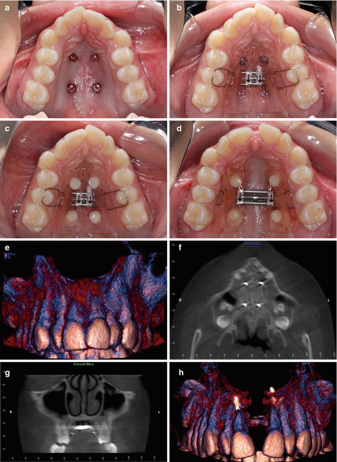
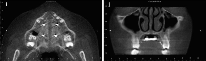
Fig. 7.7
Acrylic-type design. (a) Four miniscrew implants were placed in midpalatal region. (b) Acrylic-type RPE was tried in. There was a relief under the acrylic and occlusal rests were preventing the acrylic touching the palatal tissue. (c) RPE was secured with the flowable composite. (d) Occlusal view of post-expansion. (e) 3D surface rendering from CBCT, pre-expansion. (f) Transverse view of CBCT, pre-expansion. (g) Coronal view of CBCT, pre-expansion. (h) 3D surface rendering from CBCT, post-expansion. (i) Transverse view of CBCT, post-expansion. (j) Coronal view of CBCT, post-expansion
7.4 Hybrid Design
It is quite possible to use both bone anchorage and tooth anchorage for RPE at the same time. There have been only a few articles to show two anterior miniscrew implants and two posterior bands [16–17]. When teeth normally used for anchorage are missing, hybrid RPE can be used (Fig. 7.8). The finite element simulations suggest that the hybrid RPE appliance is capable of minimizing many of the periodontal side effects associated with the tooth-anchored RPE [16–19].
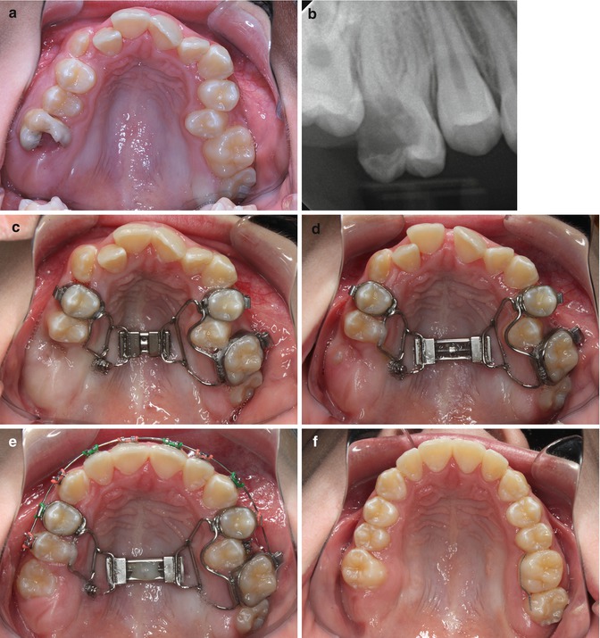
Fig. 7.8
Hybrid design. (a) Note severe caries on the maxillary right first molar. (b) Periapical radiograph of the maxillary right first molar. (c) Occlusal view of pre-expansion. (d) Occlusal view of post-expansion. (e) Bond the upper arch. (f) Occlusal view of posttreatment
7.4.1 Considerations
With no direct attachment of the posterior teeth, banding and bonding are carried out with the expander in place; as a result, leveling and alignment can be started while keeping the expander for the purpose of consolidating the expansion. It may be that the overall treatment time is shortened. One of the common problems of a tooth-anchored RPE is bite-opening effect due to the extrusion of the palatal cusps of the maxillary posterior teeth along with the buccal crown tipping. However, bone-anchored RPEs for open bite patients seem not to show much vertical change after the expansion because dentoalveolar tipping happens much less than tooth-borne RPE. For patients who have periodontal disease or very thin alveolar bones around the posterior teeth, bone-anchored RPE may be a good option for expanding the maxilla without compromising the periodontal health.
7.4.2 Surgically Assisted RPE (SARPE) with Bone-Anchored Expander
Recently there have been reports of successful nonsurgical maxillary expansion in adult patients [20–21]. However, SARPE is considered as the standard procedure to correct the narrow maxilla width in adult patients [22–23]. Typically a tooth-anchored expander is used in SARPE, but it has been shown that there may be periodontal complications as a result of stress on the anchoring teeth [24–28]. Bone-anchored expanders followed by Le Fort I surgery have been used, and they have produced successful results [24, 25, 29, 30–32]. Reportedly, the benefits of bone-anchored expanders for SARPE [11, 12, 27, 33–35] have proven to be a reliable and suitable technique for maxillary expansion without causing significant dental and periodontal damage [13, 36].
7.4.3 Possible Alternative for SARPE
One study showed that nonsurgical maxillary expansion was achieved with hybrid expander in a young adult male patient [37]. According to the adult cadaver simulation with a tooth-anchored RPE, there was no sutural opening, but rather an unwanted rupture of the alveolar process or a tooth rupture through the alveolar bone [38]. In contrast, there was a successful separation of the intermaxillary suture, which was achieved in a bone-anchored RPE. A finite element model simulation shows that it needs a relatively low transverse force to open the intermaxillary suture with a bone-anchored RPE. A high tensile stress was concentrated only on the palatine suture, and the overall stress distribution on the remaining skull is almost negligible [39]. The bone-anchored RPE does not affect the position of the teeth, and the effect on the alveolar process is insignificant (Fig. 7.9). Lee et al. studied the stress distribution and the displacement of the maxilla and teeth according to the different designs of bone-anchored RPE [19]. According to their results, the acrylic-type design expanders with miniscrew implants placed at the palatal slope showed the palatal expansion without buccal inclination of the dentition (Fig. 7.10). Although there needs to be more studies done to prove this, a bone-anchored RPE without surgery may be a possible alternative to SARPE in certain cases, especially for young adults (Fig.7.11).
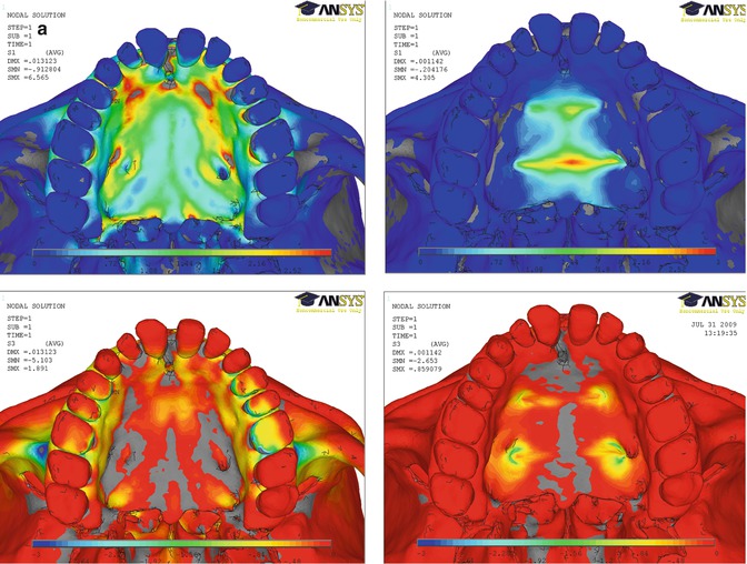
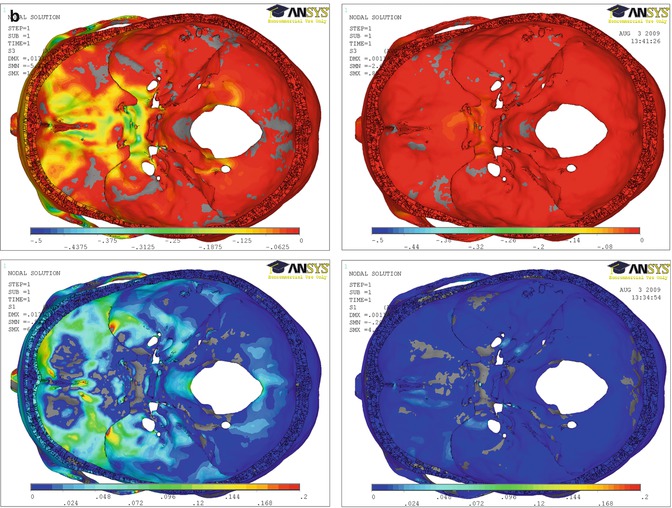
Fig. 7.9
Finite element simulation with the tooth-anchored RPE and bone-anchored RPE. (a) Finite element simulation of a transverse force application with the tooth-anchored RPE and bone-anchored RPE (From Boryor et al. [39]). Upper left: Tensile stress distribution with the tooth-anchored RPE. Lower left: Compressive stress distribution with the tooth-anchored RPE. Upper right: Tensile stress distribution with the bone-anchored RPE. Lower right: Compressive stress distribution with the bone-anchored RPE. (b) Finite element simulation results of the stress distribution on the inner cranial base with the tooth-anchored RPE and bone-anchored RPE. Upper left
Stay updated, free dental videos. Join our Telegram channel
VIDEdental - Online dental courses


