Introduction
Corticotomy has proven to be effective in facilitating orthodontic tooth movement. There is, however, no relevant study to compare the biomechanical effects of different corticotomy approaches on tooth movement. In this study, a series of corticotomy approaches was designed, and their impacts on dentoalveolar structures were evaluated during maxillary canine retraction with a 3-dimensional finite element method.
Methods
A basic 3-dimensional finite element model was constructed to simulate orthodontic retraction of the maxillary canines after extraction of the first premolars. Twenty-four corticotomy approach designs were simulated for variations of position and width of the corticotomy. Displacement of the canine, von Mises stresses in the canine root and trabecular bone, and strain in the canine periodontal ligament were calculated and compared under a distal retraction force directed to the miniscrew implants.
Results
A distal corticotomy cut and its combinations showed the most approximated biomechanical effects on dentoalveolar structures with a continuous circumscribing cut around the root of the canine. Mesiolabial and distopalatal cuts had a slight influence on dentoalveolar structures. Also, the effects decreased with the increase of distance between the corticotomy and the canine. No obvious alteration of displacement, von Mises stress, or strain could be observed among the models with different corticotomy widths.
Conclusions
Corticotomies enable orthodontists to affect biomechanical responses of dentoalveolar structures during maxillary canine retraction. A distal corticotomy closer to the canine may be a better option in corticotomy-facilitated canine retraction.
Highlights
- •
A finite element model simulated maxillary canine retraction after premolar extraction.
- •
Twenty-four corticotomy approaches were simulated during canine retraction.
- •
Biomechanical responses of dentoalveolar structures were calculated and compared.
- •
An alternative approach is recommended for clinical adoption.
Two main challenges are often confronted in orthodontic treatment for adult patients: long duration and risk of side effects such as root resorption and marginal bone loss. To cope with these problems, surgical techniques are used to facilitate orthodontic tooth movement, including alveolar osteotomy, corticotomy, and distraction osteogenesis. Compared with osteotomy and distraction osteogenesis, corticotomy has become popular gradually because of the minor surgical injury, flexible approach, and operational simplicity.
Corticotomy has been demonstrated to facilitate orthodontic tooth movement effectively in the clinic. It has many advantages over more traditional orthodontics, including reduced orthodontic treatment time, more significant tooth movement, and less anchorage required. Wilkco et al attributed these effects of corticotomy to the regional acceleration phenomenon, which is characterized by an increase in the rate of bone turnover. The remodeling of alveolar bone and periodontal ligament (PDL) would be activated and aggravated after being exposed to an insult such as a corticotomy or a cortical perforation. En-block movement of the bone segment was another explanation for this technique. Corticotomy can reduce the resistance of alveolar bone to orthodontic tooth movement by breaking the continuity of the bone layer, leading to a bone-bending effect, and possibly even a greenstick fracture of the alveolar bone.
Orthodontic tooth movement is the result of remodeling of the alveolar bone and the PDL around the tooth. Two stages are included in this procedure: the delivery of orthodontic force and the biologic responses to the force. The force generated by the orthodontic appliance is transmitted to the PDL by the teeth and then to surrounding alveolar bone, contributing to the change of the mechanical environment of the dentoalveolar structure. The mechanical stimulation can trigger a series of biologic responses to regulate the deposition or resorption of the alveolar bone temporarily and spatially to facilitate tooth movement. The internal strength and distribution of the mechanical stimulation can be denoted accurately with stress and strain, rather than with orthodontic force, in consideration of the shape and size of the dentoalveolar units. The stress and strain in dentoalveolar structure can be altered by breaking the continuity of the cortical bone after a corticotomy. The change of stress or strain can be calculated using 3-dimensional (3D) finite element methods.
Three-dimensional finite element analysis is a numeric technique for simulating mechanical processes of a real physical system; it is considered to be a valid and reliable approach for calculating stress, strain, and displacement of dentoalveolar structures. This technique can be used to simulate orthodontic processes with different treatment plans and to compare their biomechanical effects without increasing the numbers of patients or animals in the sample, unlike clinical or animal investigations.
The routine treatment plan for patients with maxillary or bimaxillary protrusion is retraction of the anterior teeth after extraction of the premolars. With regard to these patients, a 2-step treatment can be used to make the canine move first during space closure. To shorten the treatment time and save anchorage, corticotomies have been used to facilitate canine movement in the clinic. Although these studies have provided useful findings, the corticotomy approach was limited. More importantly, little research regarding the biomechanical effects of corticotomy approaches on dentoalveolar structures has been done. Therefore, the aims of this study were to design different corticotomy approaches and compare their biomechanical impacts on dentoalveolar structures during retraction of the maxillary canine and to select an optimal approach for clinical adoption.
Material and methods
Construction of the basic finite element model was based on computed tomography scans (120 kV; 175 mA; slice thickness, 0.625 mm) (LightSpeed VCT; GE Healthcare, Wauwatosa, Wis) of the skull of an adult with maxillary protrusion. A surface 3D model of the maxillary alveolar bone and the dentition with the first premolars extracted was constructed from the scanned images through thresholding, region growing, and calculating 3D operations with Mimics software (version 9.0; Materialise, Leuven, Belgium). Scaling and Boolean operations were performed on the surface model of the alveolar bone and dentition to generate the cortical bone with an average thickness of 2.0 mm and the PDL around the tooth with an average thickness of 0.2 mm based on the studies of Wang et al and Lim et al with Rapidform software (version 6.5; INUS, Seoul, Korea). The orthodontic appliances, including edgewise brackets for the anterior teeth and premolars, buccal tubes for the molars, square wires, and miniscrew implants, were designed and modeled according to clinical applications in computer-assisted design software (version 2011; Solidworks, Vélizy-Villacoublay, France). The brackets and buccal tubes were placed on the center of the labial or buccal surface of the clinical crown of the teeth. The implants were placed in the interradicular space between the first molar and the second premolar. All components were saved in initial graphics exchange specification format and imported into Abaqus (version 6.11; Solidworks). The bases of the brackets and buccal tubes were subtracted from the corresponding teeth to create a matching geometry. Then the alveolar bone, teeth, PDL and orthodontic appliances were assembled to form the geometric model. Volumetric meshes of these components in the model were created separately. The types and numbers of elements and nodes are listed in Table I
| Types of element | Nodes (n) | Elements (n) | |
|---|---|---|---|
| Teeth | C3D4 | 34037 | 166707 |
| PDL | C3D20R | 589521 | 140402 |
| Trabecular bone | C3D4 | 29405 | 139600 |
| Cortical bone | C3D10 | 79619 | 40356 |
| Bracket | C3D4 | 28097 | 116846 |
| Square wire | C3D8R | 1233 | 540 |
The first step of simulation of the corticotomy approach was to design and build a shear band corresponding to the approach in Solidworks. Then cortical bone was subtracted by the shear band to generate the model in Abaqus. Twenty-four models were built in this study. These models can be classified as follows.
For the corticotomy approaches with the position of the cuts varied, the corticotomy cuts were in cortical bone around the maxillary canine. There were 4 basic cuts: mesiolabial, mesiopalatal, distolabial, and distopalatal. Other approaches were the various combinations of these cuts and combinations with labial and palatal cuts. There were 20 corticotomy approaches designed and modeled ( Fig 1 ).
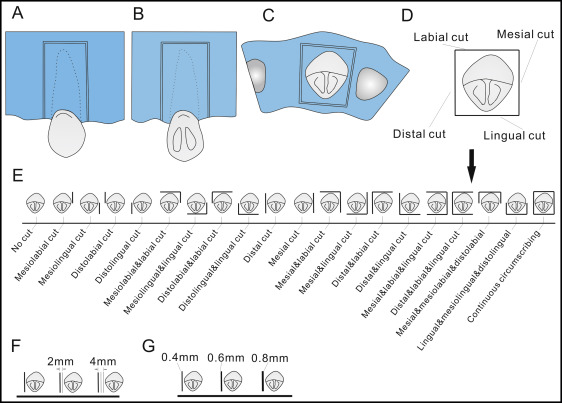
For the corticotomy approaches with the distance to the canine varied, 2 other cuts parallel to the distal corticotomy were designed at the extraction side. They were 2 and 4 mm from the distal corticotomy cut, respectively ( Fig 1 ).
For the corticotomy approaches with the width of the corticotomy cut varied, the width of the corticotomy cuts above was set at 0.4 mm according to the diameter of the bur used for corticotomies in the clinic. Two other cuts with widths of 0.6 and 0.8 mm were designed on the base of the distal corticotomy cut ( Fig 1 ).
Five materials were used in this study. All materials were assumed to be homogeneous, isotropic, and linearly elastic. The material properties were determined from the values documented in the literature ( Table II ). Then the material properties were assigned to cortical bone, trabecular bone, teeth, PDL, and orthodontic appliances.
| Young’s modulus (MPa) | Poisson’s ratio | Reference | |
|---|---|---|---|
| Cortical bone | 10.7E3 | 0.3 | Aversa et al |
| Trabecular bone | 9.7E2 | 0.3 | Aversa et al |
| Teeth | 20.7E3 | 0.3 | Lee and Baek |
| PDL | 50 | 0.45 | Lin et al |
| Brackets and stainless steel wire | 200E3 | 0.3 | Canales et al |
Canine distalization is the first step of space closure in a 2-step treatment. To eliminate the complex constraints of square wire on the canine and to facilitate its movement, the segmented arch technique was used in this study. The maxillary incisors, ipsilateral molars, and second premolars were connected with 3 pieces of square wire. The bilateral canines were not tied to the square wire to let them move freely. To prevent separation and slippage, binding constraints were used to define these interfaces: square wire-bracket, tooth-bracket, PDL-tooth, trabecular bone-PDL, and cortical bone-trabecular bone. The miniscrew implants were not involved in calculations of finite element models, and they were used to indicate the direction of the orthodontic load ( Fig 2 ).
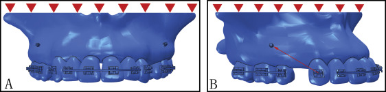
All these models were restrained at the nodes on the maxillary bone at the base of nasal cavity in all degrees of freedom. To simulate retraction of the maxillary canine, a 100-cN concentrated force was applied to the middle points of the bracket slot toward the crown notch of the miniscrew implant according to the clinical condition ( Fig 2 ). The displacement of the canine, stress distributions in the canine root, and strain distributions in the PDL and the trabecular bone were analyzed with Abaqus software.
Results
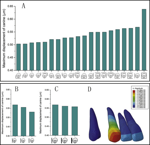
The displacements of the canines were observed in a newly defined coordinate system: origin-anterior nasal spine; x-axis, the line through posterior nasal spine; and the x-y plane–middle sagittal plane. The initial displacement of the canine showed distal movement combined with clockwise rotation, and the largest displacement of the canine was highly concentrated on the cusp in all models ( Fig 3 ). The position of the corticotomy had an obvious effect on the displacement of the canine. The maxillary canine in the model with the continuous circumscribing cut showed the greatest displacement, and larger displacements were found in models with distal corticotomy cuts and their combinations. However, no notable difference of canine displacement was observed in models with distopalatal and mesiolabial cuts and in the model with no corticotomy. As the distance between the canine and the corticotomy increased, the displacement of the canine decreased gradually. The width of the corticotomy cut had no obvious influence on the canine displacement ( Fig 3 ).