(1)
InLaser Rome – Advanced Center for Esthetic and Laser Dentistry, Rome, Italy
(2)
Arizona Center for Laser Dentistry, 7900 E. Thompson Peak Parkway #101, Scottsdale, AZ 85255, USA
Abstract
PIPSTM is an advanced laser-activated irrigation process by which photons of light are emitted in very low energy levels and with short microsecond pulse duration. PIPSTM utilizes a unique tapered and stripped tip design that allows for lateral dispersion and propagation of the generated shock wave in liquids at subablative levels, via photoacoustic and photomechanical events avoiding the possibility of thermal damage and allowing for effective three-dimensional streaming of fluids when the correct specific parameters and protocols are used. By virtue of lower energy and high peak power, unique tip design, and its positioning far from the apex, PIPSTM provides safe and effective activation for exchange of irrigants. The tip is kept stationary in the coronal aspect of the access preparation only thus offering effective irrigation with a minimally invasive instrumentation optimizing the conservation of the dentin structure and thus avoiding the possibility of laser thermal damage to dentin walls. The use of NaOCl and EDTA along the correct protocol improves the cleaning and decontaminating effect for root canals when compared to conventional methods.
Keywords
PIPSPhotoacousticShock waveSubablativeLaser-activated irrigation
11.1 Introduction
PIPS is an acronym first described by Enrico DiVito (2006) and stands for photon-induced photoacoustic streaming.
It is a patented and trademarked term that covers both PIPSTM tip design and protocols.
PIPSTM is an advanced laser-activated irrigation process by which photons of light are emitted at very low energy levels and with short microsecond pulse duration. Unlike other forms of laser-activated irrigation, PIPSTM utilizes a unique tapered and stripped tip design that allows for lateral dispersion and propagation of the generated shock wave in liquids at subablative levels, via photoacoustic and photomechanical events. This avoids the possibility of thermal damage and allows for effective three-dimensional streaming when the specific parameters and protocols are used.
The term PIPS is often improperly used to describe the use of generic tips to activate the intracanal fluids without using the specific PIPSTM tip, laser, and settings and also without following the science behind PIPSTM: an advanced protocol of laser activation of the irrigants.
The PIPSTM protocol is validated by several in vitro studies and supported by a strong body of both published and non-published experiments and data. PIPSTM has been confirmed by thousands of clinical trials and differs from the other investigated LAI techniques in the following way:
-
It uses a specific and unique tip design.
-
It uses subablative or minimally ablative energy.
-
It is delivered via a very short pulse duration thus producing a very high peak power.
-
It requires an easy positioning of the tip in the pulp chamber only and not into the canal.
-
It advocates minimal root canal and apical preparation.
By virtue of lower energy and high peak power, unique tip design, and its positioning far from the apex, PIPSTM provides safe and effective activation for exchange of irrigants when the proper protocol is followed.
Unlike other LAI techniques, PIPSTM technique is based on new “minimally invasive” or “biomimetic” concept that minimizes the use of intracanal instrumentation without compromising the ability for irrigation to effectively reach all aspects of the root canal system (Figs. 11.1 and 11.2).
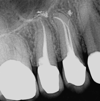
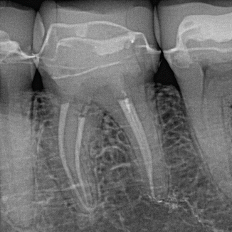

Fig. 11.1
Upper first and second premolars showing conservative shaping and obturation after PIPS

Fig. 11.2
Lower first molar showing minimal shaping of four canals and obturation post-PIPS
This optimizes the conservation of dentin structure and avoids the possibility of laser thermal damage while creating superior cleaning and decontamination through more copious and effective exchange of irrigation activated by PIPSTM. The need for enlarging and shaping of the canal system to remove infected dentin and to assure sufficient space for an appropriate flushing of irrigants, as suggested in the modern endodontics [1], is no longer necessary.
11.2 PIPS in Brief
In Chap. 10, the different LAI techniques investigated in the last 8 years were reviewed. It is evident that all the studies published in the peer-reviewed literature lack uniformity in the materials and methods used. However all the studies resulted in improved smear layer removal and bacterial reduction when compared to the other conventional irrigation techniques [2–10].
After several preliminary investigations, testing the more appropriate laser wavelength and settings, the first PIPS study on root canal cleaning dates back to 2010 (online since 2010, published in 2012) and was performed using an Er:YAG laser (Fidelis III, Fotona; Ljubljana-SLOVENIA) at 20 mJ and 15 Hz to activate the irrigant EDTA for smear layer removal [11]. Later, Peters et al. (2011) published the first PIPS study on root canal disinfection, performed with an older model of Er:YAG laser (Fidelis, Fotona; Ljubljana-SLOVENIA) at 50 mJ, 10 Hz, to activate the intracanal irrigant NaOCl [12].
In review of the published studies on PIPS, the more obvious and important values are the lower laser settings and less invasive root canal preparations required for treatment. Also of significant merit is the safe and less technique-sensitive positioning of the PIPS tip not in the canal but rather in the coronal pulp chamber only [11–15].
Photon-induced photoacoustic streaming (PIPSTM) uses a cutting-edge erbium:YAG laser technology (2940 nm) at high peak power to pulse extremely low energy levels of laser light to generate photoacoustic shock waves into liquid-filled root canals. PIPS actively pumps the fluid three-dimensionally into the main canal, lateral canals, fins, anastomosis, and dentin tubules to the apex (Fig. 11.3). With the irrigant continuously delivered in the pulp chamber during PIPS activation, the resultant shock wave travels three-dimensionally in all directions and effectively debrides and removes both vital and necrotic tissue remnants (Fig. 11.4a–c). Through this laser-activated turbulent flow phenomenon, clinicians following the PIPS protocol are not required to place the tip into the canals, but the tip is held stationary in the coronal aspect of the access preparation only (Fig. 11.5). This means that the need to enlarge and remove more dentin structure normally required to deliver a standard needle, a negative pressure system, or a laser fiber is eliminated, and the smaller and more delicate anatomy commonly seen in the apical one-third is preserved (Figs. 11.6 and 11.7). Unlike other laser-activated irrigation techniques, PIPS is not a thermal event but rather a subablative one. Due to the very short pulse duration and specific PIPS design, the extremely low level of energy required to activate the irrigants is below the threshold of ablation for dentin [16, 17] (see energy threshold Sect. 4.6.1). Ledging and thermal effects that have plagued the widespread use of other conventional laser systems are completely avoided when the correct settings and PIPSTM protocol techniques are used [13, 18–20] (Figs. 11.8, 11.9, 11.10, and 11.11) (see also Figs. 5.34, 5.35, 5.36, and 5.37 in Chap. 5 and Figs. 10.3, 10.4, and 10.5 in Chap. 10).
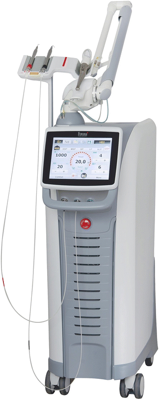
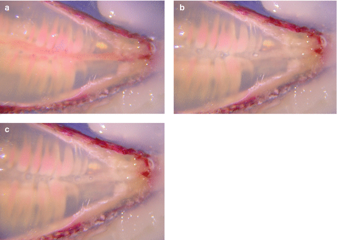
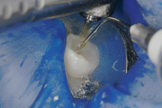
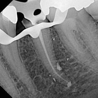
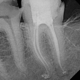
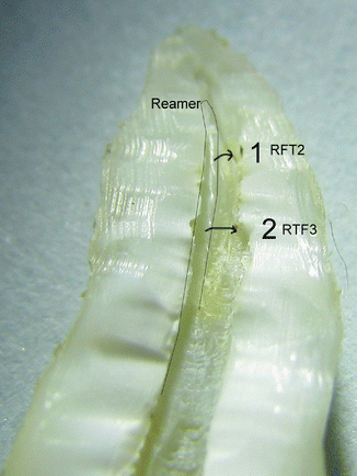
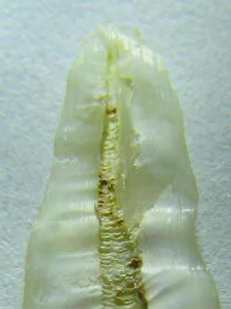
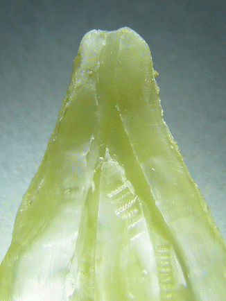
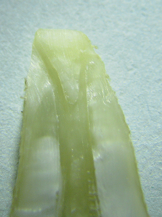

Fig. 11.3
Er:YAG and Nd:YAG LightWalker AT dual wavelength laser by Fotona (Ljubljana-Slovenia)

Fig. 11.4
(a) Cross section of single rooted, noninstrumented clarified tooth specially prepared and stained with pulp tissue in canal; (b) PIPS action shows streaming of irrigant in the canal and around nerve tissue; (c) post-PIPS application shows removal of nerve tissue from canal space with no files used (Images courtesy of Dr. Giovanni Olivi in cooperation with Drs. Augusto Malentacca and Vasilios Kaitsas, Rome, Italy)

Fig. 11.5
Proper positioning of the PIPS tip held stationary in the chamber of the access opening only. Note the syringe supplying continuous replenishment of irrigation

Fig. 11.6
Despite the minimal instrumentation, PIPS protocol allowed the obturation of multiple portals of exit in a lower second bicuspid (Courtesy of Dr. Mark Colonna Whitefish, Montana, USA)

Fig. 11.7
Lower first molar showing minimally prepared canal shapes with adequate obturation in the apical area post-PIPS (Courtesy of Dr. Mark Colonna Whitefish, Montana, USA)

Fig. 11.8
Ledging and thermal damage on root canal surface as a result of Er,Cr:YSGG laser radial tip placed into the canal as advocated with conventional protocol (Courtesy of Dr. Graeme Milicich Hamilton, New Zealand and Dr. Enrico DiVito, Scottsdale, Arizona, USA)

Fig. 11.9
Dentin surface with thermal damage and charring seen after Er,Cr:YSGG laser radial firing tip was placed in the canal and withdrawn as per protocol (Courtesy of Dr. Graeme Milicich Hamilton, New Zealand and Dr. Enrico DiVito, Scottsdale, Arizona, USA)

Fig. 11.10
Clean canal surface seen after the correct PIPSTM protocol is used. No signs of thermal damage (Courtesy of Dr. Graeme Milicich Hamilton, New Zealand, and Dr. Enrico DiVito, Scottsdale, Arizona, USA)

Fig. 11.11
Clean delta at the apical one-third of root canal seen after PIPS. Thermal damage is avoided because PIPS does not require that its tip be placed into the canal preparation at all but rather stationary in the coronal pulp chamber only (Courtesy of Dr. Graeme Milicich Hamilton, New Zealand and Dr. Enrico DiVito, Scottsdale, Arizona, USA)
11.3 Mechanism of PIPS
To date there are several studies investigating the fluid dynamics of laser-activated irrigation using both erbium chromium:YSGG laser [21, 22] and erbium:YAG lasers [4, 23]. To understand the working mechanism of PIPS, high-speed visualization methods to capture images with microsecond resolution have been performed. Also PIPS fluid dynamic studies have verified the effectiveness of PIPS (unpublished data by Drs. Peters, Jaramillo and Koch (2015), USA).
Because of the high absorption rate of the erbium laser in water, the bubble formation and its corresponding collapse create a strong pressure wave. Due to the newer and different technologies used, the shock wave is generated at lower energy levels reducing the undesirable thermal effects commonly seen with other laser systems.
11.4 Bubbles: Cavitation and Shock Wave
According to reports by other authors described in Chap. 10, when erbium:YAG laser energy is absorbed in water, an instantaneous super heating of the irrigant to the boiling point of water (100 °C) generates an initial vapor bubble expansion at the end of the tip [4, 21–24]. During expansion the bubble passes over the equilibrium state, and at its maximum volume the internal pressure is lower than the pressure in the surrounding liquid forcing the bubble to collapse. During the collapse phase a portion of energy is converted into acoustic energy with emission of acoustic shock waves [24] (Fig. 11.12).
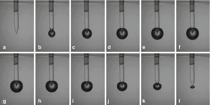

Fig. 11.12
Sequential still frame shots showing the bubble cycle with increase (a PIPS tip before activation, expansion from b–g) and subsequent decrease (collapse from h–n) of the bubble resulting in primary and secondary cavitation, seen from the PIPS tip during fluid activation at 20 mJ and 50 μs pulse duration (Courtesy Drs. L. van der Sluis, R. Macedo, B. Verhaaghen, M. Versluis, University of Twente, the Netherlands in cooperation with G.Olivi Rome, Italy)
11.5 Fluid Dynamics Study of PIPS
One of the main problems in endodontics is the fluid dynamics of the irrigants in the confined canal space. Vapor lock makes the deep penetration of the irrigant more difficult because of the absence of turbulence over much of the canal volume when using conventional irrigant devices. Accordingly, a preliminary study was performed in order to evaluate the fluid movement, distribution of turbulence, and the flow velocity inside experimental models comparing PIPS with passive ultrasonic (PUI) activation of fluids. Measurements were obtained using microscopic digital particle image velocimetry (micro DPIV). Under similar experimental conditions, the distribution and magnitude of the irrigant flow velocity stimulated by photon-initiated photoacoustic streaming device (PIPS; LightWalker, Fotona) and by a standard ultrasonic device (Suprasson P5 Booster with a 20 mm Irrisafe file tip) were gathered. A digital camera acquired images directly to the computer memory at 30 frames per second, throughout a 5s duration, for a total of 150 images for each experiment. A customized cylindrical Pyrex glass tube (5.8 mm diameter and 25 mm long), with a flat sealed bottom, filled with distilled water, was used to simulate a tooth model. The water was mixed with 5 mg/ml, silver-coated hollow glass spheres, 10 μm in diameter (S-HGS, Dantec Dynamics, Tonsbakken, Denmark), as tracing particles inside the liquid. The laser and the ultrasonic handpieces were supported by a micromanipulator to allow fine-tuning of the handpiece-tip-file with respect to the location of the tooth model. The PIPS tip was submerged 4 mm below the free water surface, while the ultrasonic file was submerged 8 mm below the free water surface. The measurements were performed on the plane of the central axis of the test glass tube, at four different locations under the PIPS tip. The first measurement area was located directly under the tip, with subsequent measurements being performed at 5, 10, and 15 mm below the tip. The Er:YAG laser was set to pulse at 15 Hz with 20 mJ pulses. The ultrasonic device was set at 50 % of scale. The measurements for the ultrasonic probe were performed in a similar manner to that of the PIPS with the tip of the ultrasonic file being just out of and above the measurement area. In the case of the ultrasonic, upon descending the measurement area 5 mm from its tip, the velocity diminished fairly quickly, and for this reason additional measurements were not taken at further distance from the probe. The measurement area locations are shown in Fig. 11.13. Data acquisition commenced 2 s before the activation of the tip.
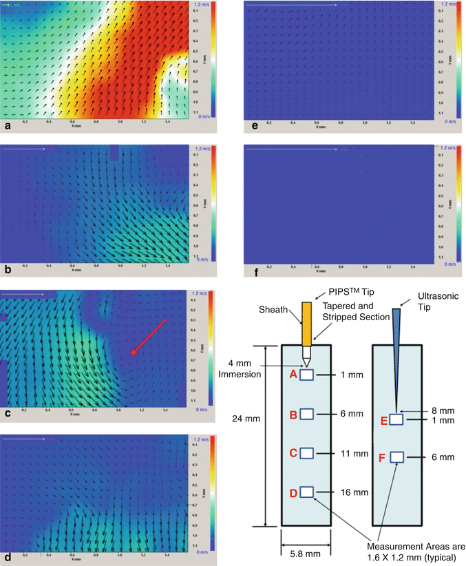

Fig. 11.13
Colored charting of fluid dynamic flow rates comparing PIPS to ultrasonics. Note the increased degree of movement with PIPS tip both near and far from the tip end position in (a–d) as compared to ultrasonic (e, f). Near tip areas of (a) and (e) show PIPS average velocities being up to 20× greater and distant areas of (d, f) show PIPS being about 10× greater than the average velocity of ultrasonic. Instantaneous velocity fields corresponding to the different measurement areas (a–f); the color represents the magnitude of the velocity vectors as indicated by the scale at right. Note the change of scale for the yellow 1 m/s reference arrow in the upper left corner of each panel. Panel e shows instantaneous velocity fields corresponding to the measurement directly under the ultrasonic tip and directly under the probe tip, corresponding to the initial spike in velocity that follows the activation of the device. Here the average velocity is 0.036 m/s, which is 20 times less than that measured for the PIPS data immediately under the probe tip as seen in panel a. Panel f corresponds to measurements 5.5 mm below the ultrasonic tip, the velocities are measured at less than 0.01 m/s showing significant decay from those of measurement area (e) (Courtesy of Dr. Ove Peters San Francisco, California, Dr. David Jaramillo USC, California in cooperation with and Dr. Enrico DiVito Scottsdale, Arizona)
11.5.1 Qualitative Observations
After 2–3 s of PIPS activation, many particles that had settled to the bottom of the test vial were resuspended and observed to be in relatively vigorous motion globally. The ultrasonic device on the other hand was visibly less effective during the 5s of the experiment and even after 20–30 s of continuous application. No substantial global motion was observed.
In the PIPS tests, the backlit videos showed an oscillating flow with a predominantly vertical velocity component. The fluid in the entire glass tube was in motion.
In the ultrasonic tests, a decrease of the velocity fluctuations was observed. The flow did not exhibit strong temporal fluctuations, and toward the bottom of the glass tube, motion was barely perceptible.
11.5.2 Quantitative Results
Test results, using digital particle image velocimetry (DPIV), showed PIPS with a 20× magnitude of difference in flow rate when compared to ultrasonic. The amplitude of the temporal oscillation was significantly higher for the PIPS experiments, corresponding to much larger flow accelerations.
Of significant finding was the remarkable fluid movement measured distant from the PIPS tip (at 5, 10, and 15 mm) when compared to the lack or nearly no movement measured much past 1 mm from the ultrasonic tip. The clinical significance of this finding is the benefit to which clinicians can effectively irrigate, stream, and improve exchange of fluids throughout the entire canal systems without the need to create larger canal spaces and remove more tooth structure as seen with current preparation and shaping techniques described in the literature (Fig. 11.13).
Another preliminary study utilized glass models as an artificial root canal for visualization of the PIPS phenomenon. Recordings with a high-speed imaging technique allowed visualization of the explosive vapor bubbles. The sequence of frames taken of the PIPS tip activated in water represented sequential frames taken at 50,000 frames per second. Given that the width of the optical probe was 600 μm, calculations for the expansion velocity of the bubble were determined. The bubble radius initially increased quite rapidly then slowed down as the bubble grows, due to the increased volume as a function of radius. The fiber width was 40 pixels corresponding to 600 μm = >15 μm per pixel. The bubble expanded from zero to a radius of 35 pixels in between the first two frames corresponding to a velocity of 26.5 m/s.
After the initial expansion the bubble then expanded more slowly, and between the second and third frame, the expansion velocity is 9.75 m/s. The expansion slowed to zero then reversed. In the final collapse between the last two frames, the inward velocity was again 26.5 m/s (see Fig. 11.12).
11.6 Parameters that Influence the Bubble Formation
11.6.1 Effect of Energy and PIPS Tip Diameter and Design
As reported in Chap. 10, Blanken et al. (2009) [21, 22] and deGroot et al. (2009) [4] observed how the size and the life cycle of the bubble depend on the energy applied and the tip used. A spherical bubble develops when a PIPS tip is used (see Fig. 11.14). This finding is consistent from other authors that refer to conical tips [23, 24]. The authors have unpublished data showing that:
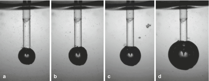

Fig. 11.14
Still frame shots showing the different bubble size resulted from different energy pulse used with PIPS at 50 μs: (a) 10 mJ, (b) 15 mJ, (c) 20 mJ, and (d) 80 mJ. The size of the bubble increases with the energy/pulse (Courtesy Drs. L. van der Sluis, R. Macedo, B. Verhaaghen, M. Versluis, University of Twente, the Netherlands in cooperation with G. Olivi Rome, Italy)
-
The higher the energies used, the greater the size of the bubbles.
-
Also observed was the longer life cycle of the radial and stripped PIPS tip when compared to the flat or conical tip alone.
-
If energy settings are kept equal, the size of the bubbles measured is greater for the larger diameter tips (Fig. 11.14).
As already reported, this finding is opposite to the concept of fluence in laser physics where for the same energy the fluence increases with smaller diameter of the fiber.
Today the use of 20 mJ is considered the standard setting for the PIPS technique in endodontics together with a 600 μm, 9 mm long tip (Figs. 11.15 and 11.16). The energy can be reduced to 15, 10, or even 5 mJ for more control in activation of the irrigant such as in the case of roots with opened apices or reduced coronal access chamber size (Fig. 11.17a–d).
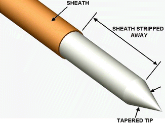
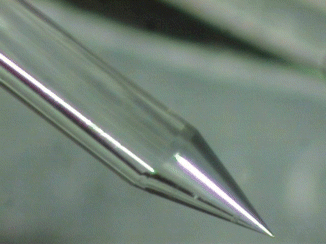
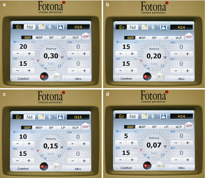

Fig. 11.15
Diagrammatic representation of the PIPSTM tapered and striped tip

Fig. 11.16
Actual close-up magnification of the tapered and stripped tip. Look at the extreme refinement and accuracy of the manufactured tip at only 600 μm diameter

Fig. 11.17
(a) The current recommended PIPS settings of 20 mJ, 15 Hz, in SSP mode (50 μ) results in an average power of 0.30 W (Peak Power = 400 W). The air-water spray is off; (b–d) the Fotona LightWalker model dashboard showing the energy settings to be lowered from 15 mJ, 0.2 W to 10 mJ, 0.15 W and to 5 mJ, 0.07 W, all at 50μs pulse duration (Peak Power 300 W, 200 W and 100 W respectively)
The radial and stripped PIPS tip emits less energy at the front of the tip, with the 4 mm stripped part improving the lateral distribution of the energy. Consecutive three-dimensional pressure waves inside the water follow the bubble implosion especially when the energy is emitted through a very short pulse duration (50 μs). The overlapping laser impulses occurring at 15 Hz generate pressure waves that rapidly travel (shock waves) in the intracanal fluids. These shock waves create rapid fluid motion and turbulence three-dimensionally and have been demonstrated to improve both smear layer and biofilm removal [25].
The larger diameter, shorter length tip, increases the surface of interaction of the laser energy with the surrounding fluid improving the efficiency of the procedure especially for the posterior teeth given the limited intra-occlusal space (Fig. 11.18). Larger tips have also been demonstrated to be more robust and durable and as such reusable for many treatments. Thinner tips can be useful in cases of small access cavities for lower incisors and upper lateral incisors (Fig. 11.19).
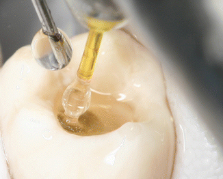
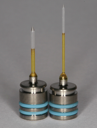

Fig. 11.18
In vivo micrograph shows the correct positioning of the PIPS tip and of the irrigation needle during PIPS: note the bubble formation around the stripped part of the tip

Fig. 11.19
PIPS™ tips: 9 mm long, 600 μm diameter tip (left) and 12 mm long, 400 μm diameter tip (right)
11.6.2 Effect of Pulse Duration
Another fundamental parameter that modulates the efficacy of PIPS activation of intracanal fluids is the duration of each laser pulse. Experiments show that the opto-dynamic energy conversion efficiency of erbium lasers, defined as the ratio between the released acoustic energy and the energy of the laser pulse, increases rapidly with decreasing pulse duration of T p approximately as 1/T p 3/2 [26]. Moreover the efficiency is approximately three times larger when a conical PIPSTM tip is used instead of a standard flat tip. The most current and technologically cutting-edge erbium:YAG laser available (LightWalker, Fotona, Slovenia) has the shortest laser pulse duration available for use with the PIPS tip. As a result, unlike other laser systems used for LAI, the very short pulse duration used with PIPS allows for very high peak powers at very low energy settings (see peak power Sect. 4.6.4). The rapid vapor bubble expansion results in strong acoustic transient waveforms during the subsequent bubble collapse oscillations. The possibility to modulate the peak power changing the pulse duration from 50 to 100 μs, as well as reducing the energy in millijoules, allows for another way to control the agitation and activation of the irrigants. For example, a reduction of the laser pulse duration from 100 to 50 μs results in a threefold increase in the opto-dynamic efficiency, meaning that three times less laser energy is required to achieve the same effect with the shorter pulse duration. This is very important if we consider the limited space where the laser-irrigant-dentin interaction takes place.
The triad of “tip design, low energy, and short pulse duration” is the key of the effectiveness and efficiency of the PIPS technique.
11.7 Conditions that Influence PIPS Efficiency and Safety
In addition to the factors already reported that influence the efficacy and efficiency of laser activation of the irrigants (pulse energy, tip diameter, design, and pulse duration), can also be the wavelength used, the pulse frequency, the continuous or intermittent irrigation, the location of different tip positions, as well as the size of apical preparation and the root canal shaping can also affect the efficiency and safety of the protocol used.
11.7.1 Effect of Different Wavelengths
Early investigations were started using the Er,Cr:YSGG wavelength (2780 nm). PIPS today utilizes the Er:YAG laser due to its higher efficiency and selective interaction with water. It is important to note that a laser energy threshold exists below which no acoustic transients are generated. Since the laser energy threshold depends inversely on the absorption coefficient [16, 17], laser wavelengths with high absorption coefficients in the irrigant are more suitable for laser activation.
The Er:YAG wavelength (2940 nm) has an advantage since it has the highest absorption coefficient for water and thus exhibits lowest threshold of energy for laser activation. For example, the laser energy thresholds for Er,Cr:YSGG (2780 nm), Nd:YAP (1340 nm), and Nd:YAG (1064 nm) laser wavelengths are, respectively, approximately 3×, 1000×, and 10,000× higher as compared to that of erbium:YAG (see Fig. 10.1 in Chap. 10).
Consequently wavelengths that demonstrate lower absorption properties in water require more energy to produce similar cavitation effects [27]. The longer pulse duration of the Er,Cr:YSGG laser also affects both quality and temperature rise on the dentin surface. As already reported, the use of parameters that can create good agitation in water, 50 or 75 mJ for the Er,Cr:YSGG laser, also creates thermal events to the root canal surface when the tip is positioned inside the root canal by virtue that the energy levels are in the ablative range of dentin [16, 17] and depletion of irrigant occurs (see Figs. 10.8, 10.9, 10.10, and 10.11 and also Figs. 5.34, 5.35, 5.36, and 5.37 in Chap. 5 and Figs. 10.3, 10.4 and 10.5 in Chap. 10).
11.7.2 Effect of Pulse Frequency
Studies from the authors demonstrated 15 Hz (or pps) as the preferred repetition rate to assure an efficient activation and recycling effect of the liquid in root canal model. Measurements using the standard protocol of 30 s cycling during PIPS laser activation yielded turnover of irrigants some 15×. Also noted was the effective removal of vapor lock often seen when using conventional manual and ultrasonic irrigation techniques. Lower repetition rate resulted in less efficacious exchange and greater splashing and dispersion of liquids out of the pulp chamber.
11.7.3 Effect of Continuous or Intermittent Irrigation
The presence of liquid in the canal system during the laser activation is also important. It has been suggested by several authors that intermittent irrigant flow within a limited time (5s) be used instead of the continuing flowing technique (see Chap. 3). The rest phase allows sodium hypochlorite to react and the following phase to replace the consumed solution with fresh active solution.
PIPS technique requires continuous flowing of the irrigants for 30s, not only to activate the solutions but also to promote, via the shock wave, a cleaning action of the dentin surface. After a longer agitating and activating phase, a rest time (rest phase) is necessary for the reaction rate of the solutions [28]. Effectively, if short time and intermittent irrigation (5s) does not maintain continuous presence of liquid during laser activation and if the tip is positioned incorrectly inside the canal and/or the energy applied is high, the fast consumption of the irrigant inside the apical and middle one-third of the canal produces depletion of the liquid in the apical portion. This leads to dry interaction on the dentin and consequently thermal damage from ineffective hydration, jeopardizing the results of the PIPS technique as reported in a recent study in which constant irrigant was not maintained [29]. The two steps of continuous agitation/activation and rest phase are fundamental for successful irrigation when using the PIPS technique. Following the proper PIPS protocol is critical for optimal results (Figs. 11.20, 11.21, 11.22, and 11.23).
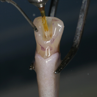
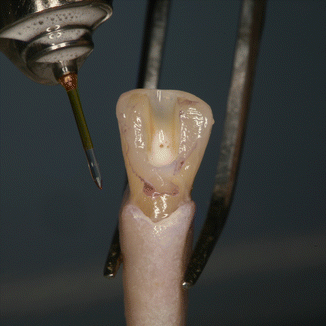
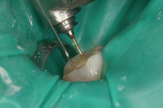
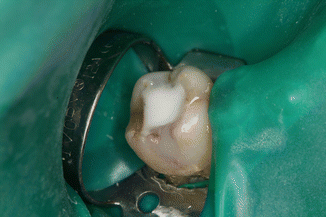

Fig. 11.20
The 600 μm PIPS tip is held stationary in the coronal access opening only and not into the canal itself

Fig. 11.21
During the required “resting phase” of 30s, a high consumption of available chlorine is seen as effervescence

Fig. 11.22
In vivo micrograph of lower first molar showing correct positioning of irrigation and PIPS tip for laser-activated irrigation: note the 27G needle resting to side of handpiece head

Fig. 11.23
Release of chlorine during the 30 s rest phase after PIPS laser activation shows foaming action
11.7.4 Effect of Tip Position in the Pulp Chamber
Comparing data from PIPS studies [11–15] with those from LAI (Table 10.2), it is evident that confusion still remains in LAI procedures on how far the laser tip should be kept away from the apex to allow efficient and safe cleaning and disinfection of the root canal.
Many disadvantages are related to the position of the tip inside the canal:
-
Curved or complex anatomy may be problematic for negotiation by a laser fiber tip, as well as needle or ultrasonic files or negative pressure probes (Fig. 11.24).
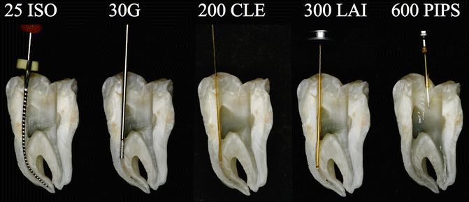 Fig. 11.24Split section of lower molar with three canals: A steel K-file ISO#25 positioned 1 mm shorter of the apical terminus of curved mesial canal; the flexibility of the instrument follows the root canal anatomy. A 30G endodontic needle cannot reach the working length resulting in ineffective irrigation. A 200 μm near infrared laser fiber (conventional laser irradiation) is not able to follow the curvature of the shaped root canal; as a consequence the tip enters in contact with dentinal walls along the curvature, producing hot spots; also the wanted decontamination effect fails. A 300 μm tip (laser-activated irrigation) is positioned 5 mm shorter of the apical terminus: the tip itself creates an obstacle to the flow of irrigant from the tooth entrance, and a possible depletion of irrigant may occur in the apical part resulting with ineffective irrigation and thermal hot spots. PIPS is easy, safe, and effective, far from the apex, and does not require that it be placed in the canals. It allows for multiple canal irrigation at same time regardless of the shape or anatomy
 -
Larger and more invasive preparations are required to create space for the 300 or 400 μm fibers in the apical one-third portion of the canal (Fig. 11.25).
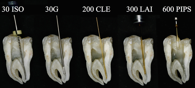 Fig. 11.25Split section of lower molar with three canals: a steel K-file ISO#30 positioned 1 mm shorter of the apical terminus of straight distal canal. Also here the 30G endodontic needle cannot reach the working length with ineffective irrigation. Also the 200 μm near infrared laser fiber (conventional laser irradiation) is not able to follow the curvature of the root canal in the apical one-third. A 300 μm tip (laser-activated irrigation) is positioned 5 mm short of the apical terminus. PIPS is easy, safe, and effective, far from the apex, and does not require that it be placed in the canals
 -
When a flat or conical laser tip is positioned close to the apex (1–5 mm), keeping it stationary or moving it up and down during LAI procedures [2–8], irrigant extrusion can result at the apical terminus as described [23, 30] (Fig. 11.26).
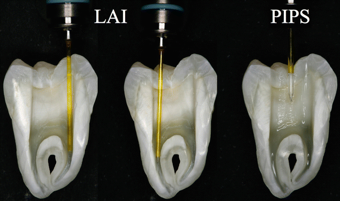 Fig. 11.26Comparison between PIPS and LAI protocol: the tip positioned close to the apex (1–5 mm), during LAI procedures, may create irrigant extrusion and liquid depletion during laser activation of irrigantsWhen a tip is positioned in the apical or middle one-third of the canal, the tip itself becomes an obstacle to the flow of irrigant from the tooth entrance, and a possible depletion of irrigant may occur in the apical part. The larger the diameter of the tip, the more it occludes the canal thus decreasing the flow of irrigant from the coronal to the apical portion.
 -
Moreover, it is impossible for the clinician to observe and be sure if the fluid level in the apical part is being maintained or if depletion occurs. Depletion of the irrigant results in thermal damage with laser spots seen on the dentin surface.
It is important to note that the use of high energy inside the canal leads to a faster vaporization and depletion of fluids and unwanted ablative effects (see Figs. 11.8, 11.9, 11.10, and 11.11; see also Figs. 10.3, 10.4, and 10.5 in Chap. 10).
On the other hand, PIPS protocol does not require that the tip be placed into the canals at all, but rather in the pulp chamber only (see also Figs. 11.5, 11.18, 11.22, and 11.27).
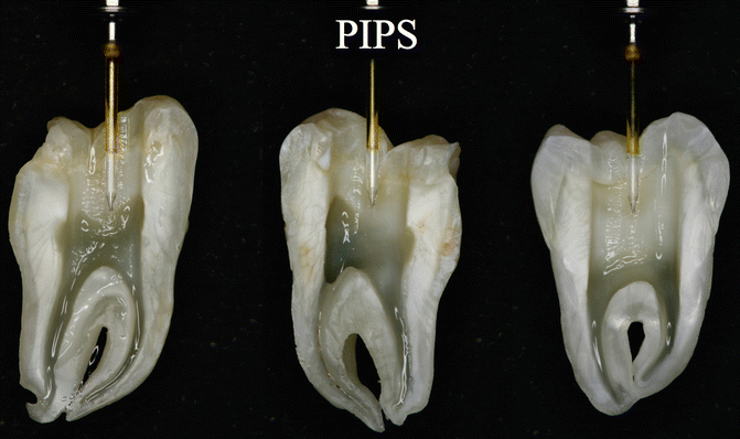

Fig. 11.27
PIPS tip correctly positioned in pulp chamber: note the border of the stripped part positioned at occlusal margin of the cavity and the tip not in contact with dentin walls: as a consequence all the canals can be irrigated both effectively and safe
Several advantages are related to positioning of the PIPS tip in the pulp chamber only:
-
The absence of need to enlarge and remove more tooth structure as required to deliver a fiber inside the canal.
-
Increased ability to efficiently irrigate all the root canal length, including the isthmus and lateral canals frequently present in the coronal and middle one-third, otherwise not irrigated when the tip is inserted into the canal.
-
Increased ability to efficiently irrigate complicated anatomical systems including curved canals that would otherwise be difficult to irrigate with other techniques.
-
More conservative negotiation of smaller and more delicate anatomy commonly seen in the apical one-third.
-
The position of the laser tip far from the apex decreases the possibility of apical extrusion (this part will be discussed later).
The tip is kept stationary in the coronal aspect of the access preparation only thus offering a less technique-sensitive application for achieving good irrigation. The result is a canal convenience form that is more conservative, minimally invasive, and biomimetic avoiding the unnecessary removal of tooth structure (Figs. 11.28a–d and 11.29a, b).
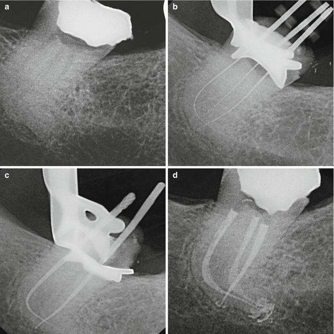
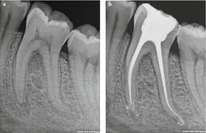

Fig. 11.28
(a) X-ray of the lower third molar showing accentuated curvature of distal root; (b) thin and flexible files to negotiate the apices; (c) gutta-percha master cone check; (d) root canal obturation with very conservative shaping of root canals (Courtesy of Dr. Enrico DiVito, Scottsdale, Arizona, USA)

Fig. 11.29
(a) Pre-treatment radiograph of the lower first molar; (b) post-re-treatment radiograph. Note the conservative obturation (20/04) shape that can be achieved with the use of PIPS laser-activated irrigation (Courtesy of Dr. Paolo Magliano, Torino, Italy)
11.7.5 Apical Preparation and Root Canal Shaping Using PIPS
This is yet another key distinguishing point of the PIPS technique.
The ability of photon-induced photoacoustic streaming to drive irrigants three-dimensionally into the root canal system by positioning the tip in the pulp chamber only where the irrigant reservoir can be maintained and visualized is complementary with the new “minimally invasive” philosophy in endodontics. Without the need to position any device (needle, ultrasonic tip, negative pressure system, or laser fiber) inside the canal, PIPS advocates minimal root canal and apical preparation while still allowing for efficacious movement and exchange of irrigants and effective cleaning and decontamination needed prior to establishing hermetic apical sealing during obturation. To maintain the natural or preexisting size of the anatomic apical constriction and to reduce the size of the preparation at a working length, PIPS technique advocates instrumenting 1 mm shorter than the measured working length from the anatomical apex. This approach maintains the natural delicate morphology often seen in the last 3 mm of the apical third while better controlling the possibility for blockage, transportation, and apical extrusion.
Zhu et al. (2013) reported that the effectiveness of PIPS may be influenced by a larger canal size, as it would reduce the superior efficacy of the PIPS, because the conventional needle or other systems can reach the apical third easier by virtue of sacrificing more tooth structure thus yielding no difference in their disinfecting ability [31].
This observation will be extensively debated ahead, in the discussion part.
11.7.6 Apical Extrusion
Different conditions, closely related one to another, can create extrusion.
11.7.6.1 Wide Apical Foramen
The apical foramen size depends on the “status quo ante” of the tooth.
Usually vital and necrotic teeth maintaining intact apical openings have a natural constriction ranging from ISO #08 to #20 [32, 33]. These clinical situations permit minimal and biomimetic approaches that limit the apical preparation to ISO #20–25. When chronic pathology leads to an apical reabsorption with a wide apical opening, or as seen in the case of immature teeth, care must be taken during the laser activation of the commonly used irrigants. PIPS protocol allows for the reduction of energy (from 15 to 5 mJ) reducing the peak power and consequently the photoacoustic effect limiting the force of the pressure waves in apical direction.
11.7.6.2 High Pressure Inside the Canal
Accordingly to George and Walsh (2008), high pressure inside the canal depends on the energy applied and on the position of the tip (c) [30].
11.7.6.3 Tip Position
During LAI procedures, when a flat or conical laser tip is positioned close to the apex (1 or 5 mm) either stationary or in movement, irrigant extrusion from the apical terminus was described [23, 30]. Essentially the closer the tip is to the apex, the more the pressure wave can create extrusion (see Fig. 10.9).
PIPS uses lower energy in comparison with other different LAI protocols and a safer position of the tip in the pulp chamber.
When the tip is positioned in the pulp chamber and held stationary without entering the canal orifices, no irrigant extrusion was observed by Peeters and Mooduto (2013) [34]. Possible fluid dynamic explantations include passive reflux event, surrounding periodontal ligament pressure, and intraosseous vascular pressures measured at 5.7 mm of Hg from Khan et al. (2013) creating a positive pressure that can preclude extrusion [35–38]. The capillary blood pressure in the human body is reported to be approximately 25 mmHg in the capillary bed, higher at the arterial end of the capillaries, and 10–15 mmHg at the venous end [39].
Apical extrusion of irrigants remains a controversial and debated issue, still under investigation. However the authors observed no extrusion during clinical trials when the proper PIPS protocol was used.
11.8 Temperature Variation
Because of the low energy used (20 mJ or less) and its complete absorption in water, no significant temperature rise was recorded on the root surface.
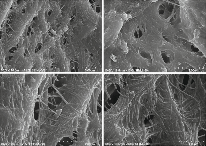
DiVito et al. (2012) [11] in an in vitro morphological study investigated the possible thermal side effects of erbium:YAG laser activation (20 mJ per pulse, 15 Hz, and 50 μs pulse duration, 400 μm PIPS tip) of 17 % EDTA, used for smear layer removal. Temperature variations on the external root surface of the teeth of the laser groups were measured by a modified thermocouple sensor of 1.5 mm diameter placed on the root surface 5 mm from the apex. Temperature variations were monitored continuously throughout all the irradiation periods. Minimal average temperature increases of 1.2 and 1.5 °C were observed at the root surface during laser irradiation for 20 s and 40 s irradiation time, respectively. SEM evaluations of 5 mm in the apical third reported no laser thermal damage on the dentin surfaces (Figs. 11.30, 11.31, 11.32 and 11.33).

Figs. 11.30, 11.31, 11.32 and 11.33
Post-PIPS SEM images reveal extremely clean, undisturbed, and not thermally affected surfaces when correct PIPS protocol is followed (Courtesy of Dr. Graeme Milicich, Hamilton, New Zealand and Dr. Enrico DiVito, Scottsdale, Arizona, USA. Figs. 11.30, 11.32 and 11.33: Reprinted from DiVito et al. [11] with permission. Fig. 11.31: Reprinted from DiVito et al. [13] with permission)
11.9 PIPS Effects on Irrigants: The Activation Phase and the Resting Phase of NaOCl
Another important value of LAI and PIPS is their ability to increase not only the fluid dynamics of the irrigants but also their activation and effectiveness.
Macedo et al. (2010) [28] demonstrated that sodium hypochlorite efficacy depends on its reaction rate and on the availability of free chlorine ions, specifically the hypochlorous acid (HOCl) and the hypochlorite ion (OCl−) (Fig. 11.34). In alkaline solutions the OCl− prevails and brings with it a superior oxidative effect and a higher tissue-dissolving capacity than HOCl (Baker 1947). There is an activation phase occurring during agitation producing a significant portion of active chlorine ions. When activation is discontinued and the resting phase occurs, active ions produce chelates which are antibacterial and digestive in action on smear layer, bacteria, and other organic and inorganic tissues. The study reported that continuous agitation is a strong activator of sodium hypochlorite. In particular NaOCl solutions activated by laser and ultrasonics showed a higher reaction rate than nonactivated NaOCl solutions. LAI was demonstrated to be more effective than PUI after the 3 min of resting interval (Figs. 11.35a–d).

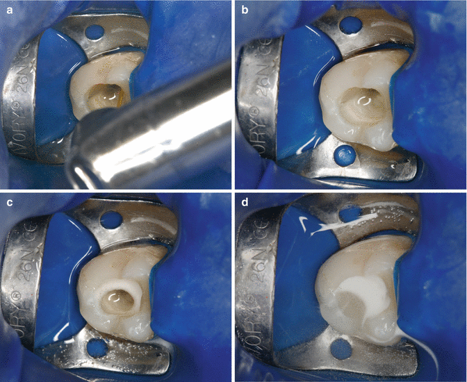

Fig. 11.34
Chemical reaction of sodium hypochlorite produces free chlorine ions, specifically the hypochlorous acid (HOCl) and the hypochlorite ion (OCl−)

Fig. 11.35
(a) Intraoperative micrograph shows the correct position of PIPS tip prior to activation; (b–d) note the higher consumption of available chlorine with foaming after 10, 20, and 30 s of resting phase following PIPS activation
11.10 Other Effects of PIPS: Vapor Lock
Van der Sluis reported that stable bubbles, such as vapor lock occurring at the apex, can be driven and eliminated by the pressure changes from the growth and collapse of the laser-induced bubble (see Chap. 3) [40]. Peeters et al. (2014) in a visualization study described the disruption of the trapped air from the apical region, caused by bubble implosion produced by the use of laser-driven irrigation [41].
Also experimental records from the authors also reported the ability of PIPS pressure waves to eliminate vapor lock from inside the artificial canal model (Olivi G. and DiVito E, 2014) (Fig. 11.36a–f).
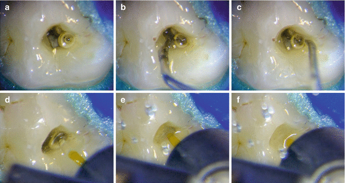

Fig. 11.36
(a–c) Ultrasonic activation not effective at removing vapor bubble; (d–f) PIPSTM laser-activated irrigation quickly removes vapor bubble
11.11 Undesired Effects: Fluid Splashing
If higher power setting (more than 20 mJ) or incorrect tip positioning is used (not completely immerged in the pulp chamber with part of the stripped portion out of the coronal opening), splashing of irrigant outside the tooth may occur. This depends on the width of the generated vapor bubble and on its consequently high pressure that pushes irrigant out of the root canal at the coronal opening causing loss of irrigant and ineffective irrigation. Unlike what was reported by van der Sluis et al. for LAI (see Chap. 3), PIPS needs continuous irrigation with an external supply to maintain constant levels of irrigant inside the canal so that the canal does not dry out thus avoiding adverse thermal effects (George and Walsh 2012) [42] or ineffective irrigation (Deleu et al. 2015) [29].
Additionally, to avoid undesired and unpleasant side effects to the patient, it is recommended that a hermetic barrier using a rubber dam be used to establish adequate isolation. Liquid dam can also be added to help achieve proper isolation. Also covering the patient with waterproof bib to protect clothing is highly recommended (Figs. 11.37 and 11.38).
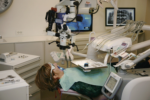
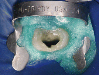

Fig. 11.37
Proper patient draping with waterproof bib to protect clothing is highly recommended to be prepared

Fig. 11.38
Proper isolation for PIPS is important. Liquid dam is interlocked beneath the dam clamp
11.12 Clinical Applications of PIPS
PIPS offers a variety of applications and results in cleaning and decontamination of the root canals clearly supported by the international literature. The ability of PIPSTM to remove medications from the root canal, such as double and triple antibiotic pastes or calcium hydroxide, and to remove filling materials from oval-shaped canals was investigated, suggesting the application of PIPS also in endodontic re-treatment.
Stay updated, free dental videos. Join our Telegram channel

VIDEdental - Online dental courses


