Lingual orthodontics
An improvement in one’s physical appearance, as is common with orthodontic treatment, can positively affect social and interpersonal interactions. With an increasing number of grown-ups opting for orthodontic treatment, adult patients form a significant segment of practise, making almost up to 40% of certain orthodontic practises. These adults have special aesthetic demands regarding their orthodontic appliance visibility, which prompted the idea of placing brackets on the lingual side, with a resultant introduction of lingual orthodontic treatment methodology.
Traditionally, banding was used to place various orthodontic attachments on teeth. Current development of lingual orthodontics began in early 1970s, when it became apparent that bonding of brackets was a viable clinical procedure and that ‘aesthetic’ plastic brackets were a compromise. Dr Craven Kurz developed a true lingual appliance, in which he bonded plastic Fischer edgewise brackets to the lingual aspect of the anterior teeth and metal brackets to the lingual aspect of the posterior dentition, for many of his aesthetically conscious adult patients. A product development team of Ormco – orthodontic product manufacturing company in California, USA – developed many prototypes of edgewise lingual appliance. The turning point in the early stages of lingual appliance development was the addition of an ‘anterior flat bite plane’ as an integral part of the maxillary brackets. This converted the shearing force produced by the lower incisors to compressive force, which was believed to facilitate the anterior intrusion and decreased bond failure.
In the early 1970s, when lingual orthodontics debuted sensationally,1,2 the number of lingual cases increased exponentially in the United States. However, this rapid increase declined within a few years.3,4 The reason for this decline is not only due to the ceramic brackets which debuted at the same time but also due to the fact that most of the lingual cases could not finish with satisfactory results, as most orthodontists started lingual treatments without understanding the peculiarities of lingual orthodontics.
Some patient-related problems like tissue irritation, speech difficulties, gingival impingement and occlusal interferences and certain operator-related problems like appliance control, appliance placement and bonding, wire placement, ligation and attaching auxiliaries were associated with lingual appliance system. However, a continued research in this field over the last few years has led to several improvements in the original lingual appliance and to a variety of new lingual appliance systems. The current lingual appliances are much more refined to address the above-mentioned problems and offer great promise in clinical practise. The development of newer appliances, invention of superelastic wires such as thermoactive wires and improvements in laboratory procedures5–12 changed the lingual orthodontic practise, making it easier and more comfortable for the patients. Current lingual orthodontic practise is completely different from the lingual orthodontic practise, 30 years ago.
This chapter deals with certain key features of lingual treatment, efficient bonding procedure and various lingual appliance systems with clinical case presentations.
Key diagnostic and treatment planning considerations
It is certainly true that lingual orthodontic appliances in their current forms have helped orthodontic professionals to provide services to a large segment of population that would not have otherwise sought orthodontic treatment. However, every patient seeking lingual orthodontic treatment should be comprehensively examined, and potential difficulties, if any, should be identified to establish appropriate treatment strategy. Patient examination, diagnosis and treatment planning are carried out in a manner similar to established standards; however, certain factors that are specific to lingual treatment mechanics must be considered in diagnosis and treatment planning process.
Patient selection
Some practitioners of lingual orthodontic therapy are quite particular about the selection of specific malocclusion patients for lingual treatment. Authors believe that all cases can be successfully treated with lingual appliance therapy; however, certain morphological characteristics of malocclusion pose challenges, and therefore, limitations to this approach.
The patient was a 12-year 9-month-old male. At first examination, the authors did not expect that such a young boy would request for lingual treatment. Molars were Angle Class II on both sides, and the upper incisors were flared out (Fig 8.1A1–D). After the upper bicuspids were extracted, the treatment began with lower arch (Fig 8.1E1–H5). Extraction spaces were closed with sliding mechanics, followed by detailing of dentition. The treatment term was 21 months, large overjet and deep overbite were overcorrected (Fig 8.1I1–J5). Maxillary and mandibular growth was observed during the treatment. Headgear was not used (Fig 8.1K). Panoramic radiograph showed a good root paralleling, and dental radiographs showed that root resorption was not observed (Fig 8.1L–M2).
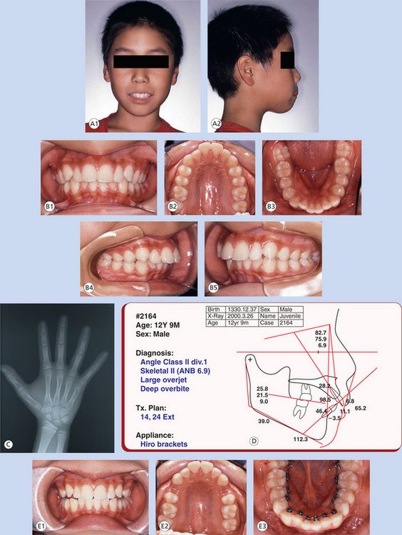
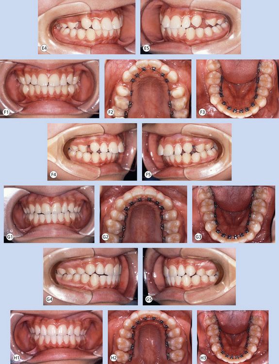
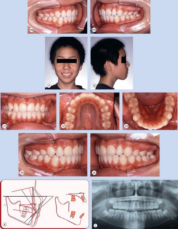
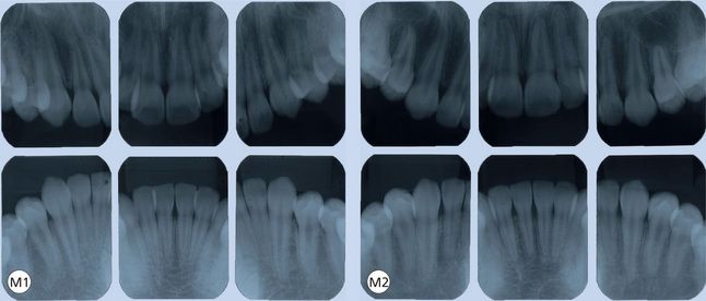
Figure 8.1 (A1 and A2) A 12-year 9-month-old male patient. He and his father requested lingual treatment. (B1–B5) Pretreatment intraoral pictures. Upper incisors were protruded. Molar relations were almost full Class II. (C) Pretreatment hand-wrist X-ray. Sesamoid bone was not appeared yet. It is about stage 3. (D) Pretreatment cephalometric tracing, diagnosis and treatment plan. He was skeletal Class II, and maxillary growth control was required. However, he did not accept it. (E1–E5) Upper bicuspids were extracted, and brackets were bonded on lower bicuspids. Initial wire was 012NiTi. (F1–F5) Four months into the treatment. Upper brackets were bonded. The archwires were 016 thermoactive in both arches. (G1–G5) Eleven months into the treatment. Space closure was done with sliding mechanics. Archwires were 1725 Beta III/0175 square titanium molybdenum alloy (TMA). (H1–H5) Sixteen months into the treatment. Finishing and detailing were done with 1725 Beta III/0175 square TMA. (I1 and I2) Posttreatment facial pictures showing pleasing smile. However, profile was not improved because of lack of maxillary growth control. (J1–J5) Posttreatment intraoral pictures showing an excellent occlusion. (K) Cephalometric superimpositions show the growth of maxilla and mandible. Anchorage loss was minimal despite not using any additional anchorage. (L) Posttreatment panoramic X-ray shows good root paralleling. Lower third molars are not extracted yet. (M1 and M2) Dental X-rays of (1) pretreatment and (2) posttreatment. Root resorption was minimal.
Bracket positioning, laboratory setup and bonding procedure
It has been universally recognized that precise bracket placement holds the key to success of the lingual treatment. Considering the difficulty in gaining access to the lingual surfaces of maxillary and mandibular teeth, indirect bonding technique remains the only viable option to control bracket placement. This makes the laboratory setup and indirect bonding procedure a standard protocol in lingual orthodontics.
The most important aspect of bracket placement in lingual orthodontics is that the required tip, torque, in-out and rotational corrections are built into the bonded brackets through the resin beneath the bracket bases. There is no predetermined bracket placement prescription in lingual technique. An accurate bracket positioning on laboratory setup models and precise transfer of the same during bonding procedure are critical steps involved in successful lingual treatment.
More than 30 years have passed since lingual orthodontics appeared.1,2 During the last 20 years, lingual orthodontics has taken very important revolutionary steps. The current lingual orthodontic practise is quite different from the lingual orthodontic practise, 30 years ago. One of the most dramatic changes is the evolution of the bonding procedures.5,6,8–12 The indirect bonding technique is pivotal for success in lingual orthodontics. The only indirect bonding technique in the 1980s was silicone tray system made with torque angulation reference guide (TARG) or customized lingual appliance set-up service (CLASS).8 Some clinicians are still using silicone trays; however, it has a lot of associated problems such as bonding inaccuracy, bonding failure and increased cost.
In the early 1990s, authors introduced an epoch-making laboratory-indirect bonding system and published it in 19988 as the resin core indirect bonding system (RCIBS). Since RCIBS has made a great impact in the lingual orthodontic world, the users did not name it RCIBS but the ‘Hiro system’. Currently, the Hiro system is becoming a widely used indirect bonding system because it has improved upon a lot of difficulties associated with the other indirect bonding systems, providing accurate bonding with minimum bonding failure. It allows rebonding and is affordable.
The laboratory and indirect bonding procedure of Hiro system
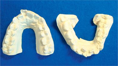
Make impression of the patients’ teeth with alginate. Hiro system does not require silicone impression materials. This is because the laboratory work of Hiro system is simple; therefore the chances of error are reduced. Models should be poured with hard plaster (Fig 8.2).
Fabricating the setup
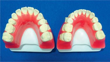
Fabricate the setup using articulators (Fig 8.3). Any kind of articulator is suitable since the purpose of mounting on an articulator is to make the laboratory work easy. Making the setup as ideal occlusion or making some over correction is dependent on the orthodontist’s treatment technique. Dr Hiro always uses ideal setup in his practise.
Prepare the ideal archwire
Once the setup has been fabricated with wax, bend an ideal archwire using full-size rectangular wire (Fig 8.4). When you have bent the anterior part, bend the bicuspid insets. Not all bonding bases will fit to the tooth surface of the dental cast, but this is fine (Fig 8.5). Do not make small adjusting bends in the archwire and keep it as smooth as possible. If you make small adjusting bends in this step, they should be continued throughout the treatment.
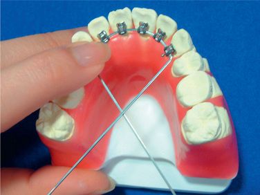
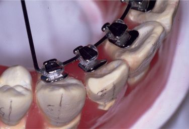
Figure 8.5 The bonding bases may not fit to the tooth surface of the dental cast, but this is fine. Do not make small adjusting bends in the archwire; keep it as smooth as possible.
Mesiodistal position: Mesiodistal position of brackets is normally the middle of the teeth for each tooth.
Bracket height: Bracket height in bicuspid-molar area is normally lower (gingival) than the centre of the crown height (Fig 8.6). Sometimes gingivoplasty might be necessary for second molars or upper canines in order to place the brackets in ideal position. Do not place the brackets higher than the functional cusps. In the upper anterior part, brackets must be placed close to their gingival margin. This positioning will help the patient’s speech and avoid interference to antagonistic teeth. In the lower anterior part, brackets must be positioned at almost the centre of the crown height. To achieve this bracket position, some cases may require vertical steps between canines and first bicuspids. Remember that if this vertical bend is made in the laboratory archwire, you must bend the archwires for the patient in the same way.
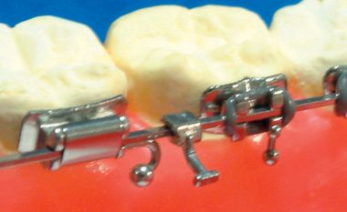
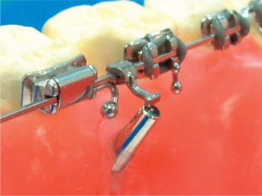
Crimp surgical hooks
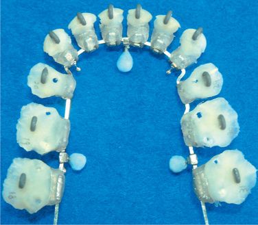
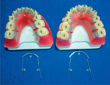
When the ideal arch is completed and the brackets positioned (Fig 8.7), remove the archwire from the setup and crimp three surgical hooks on the wire (Fig 8.8). One of the hooks is crimped between both the central incisors (Fig 8.9). Another two hooks are crimped between the first and the second molars on both the sides (Fig 8.10). Afterwards, the surgical hooks are bent lingually (Fig 8.11).

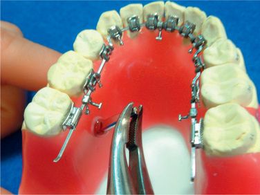
Stick dowel pins
Next, heat three dowel pins and stick them in the wax base, just under the surgical hooks (Figs 8.12–8.14).
Fabricate the attachments
Once the dowel pins are fixed in the wax, the next step is to fabricate the attachments with liquid-powder acrylic resin. Use gutta-percha at the two points of the archwire to hold it temporarily. Next, using brush on technique, cover the top of the surgical hooks and the dowel pins with the resin and connect them with each other (Figs 8.15 and 8.16). They work as attachments so that you can replace the archwire exactly in the same position. Therefore, you can reproduce new bracket positions and rebond them anytime in case the patient’s brackets break off or are lost. After the resins are cured, remove the gutta-percha and clean the model and the archwire.
Prepare the models
Block out deep and small grooves with wax (Fig 8.17). This prevents imperfect fit of cores when they are placed on the patient’s teeth.
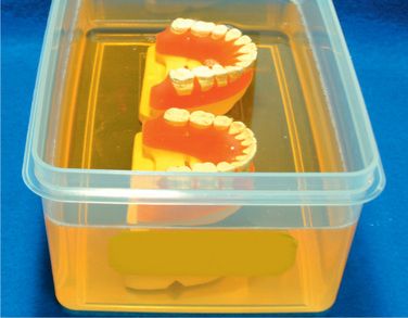
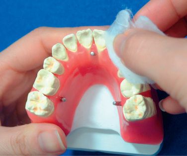
Soap the setup model
Put the setup models into a soapy liquid. After 10 min of dipping, polish them with cotton in the water (Figs 8.18 and 8.19). The purpose of soaping is to replace the application of separating medium. The authors had tried all kinds of separating media and found that this is the best way for the future laboratory steps and that the frequency of broken brackets during the treatment is minimum. Do not use vaseline as separating medium because it causes dislodgement of brackets from the teeth.
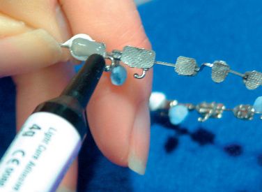
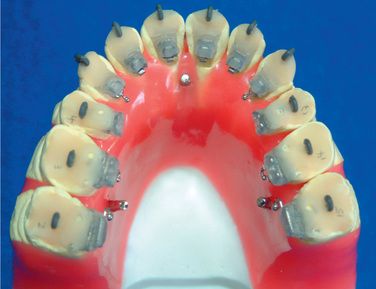
Complete the bracket prescription
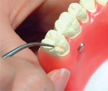
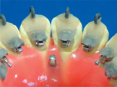
The next step is to transfer all the information of the setup to the brackets. Apply the light cure composite resin (Transbond®3M) on all of the bracket bases, set the archwire on the setup with the help of the attachments and cure them (Figs 8.20 and 8.21). Now, all the information of the setup, bracket height, angulation, in-out, rotation and torque have been transferred to the brackets.14
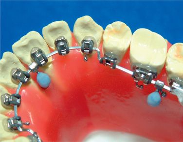
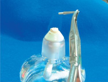
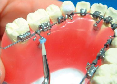
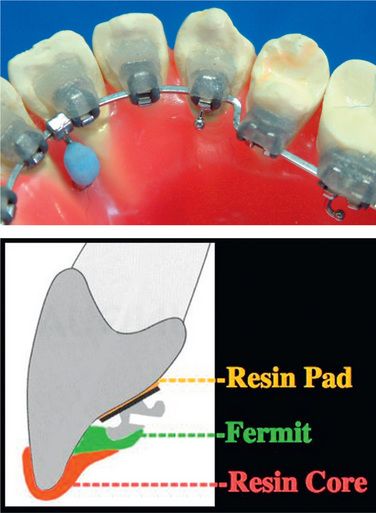
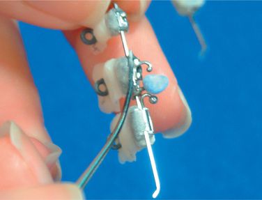
Fabricate resin cores
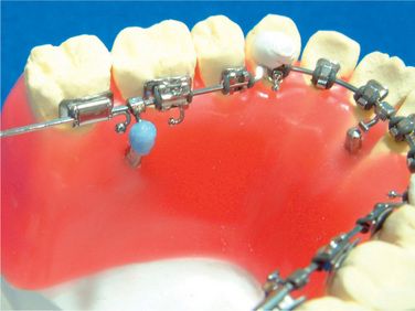
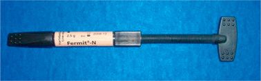
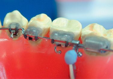
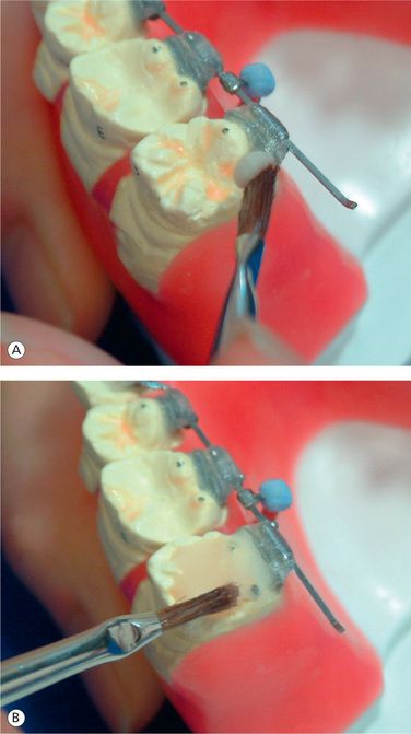
Apply small amount of provisional dental resin (Fermit® Vivadent) on the brackets, paying special attention not to cover the ideal archwire (Figs 8.22–8.24). Since Fermit has elasticity after it is cured, it is easy to remove them even through the undercut areas such as tie-wings. Do the same for all the brackets and cure. Use liquid-powder acrylic resins to fabricate resin cores (Fig 8.25A and B). Do not use composite materials such as Bandlok as core materials because it is too hard and difficult to remove.15 Before the acrylic resin hardens, put elastomeric rings on the cores for the purpose of holding resin cores when we bond them on the patient’s teeth (Fig 8.26A and B). If you make a small hole at the top of lingual cusps of each core, excess adhesive will come out from the hole when you bond them on the patient’s teeth.
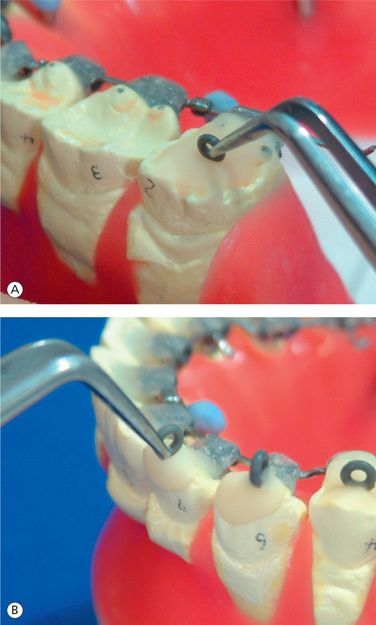
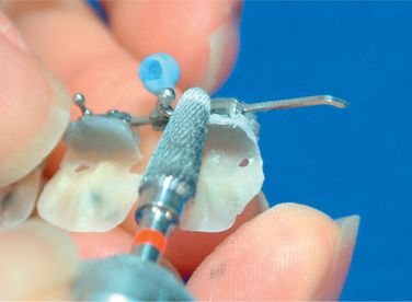
Finalizing the resin cores
After writing down the tooth number on each core, remove all the cores-brackets-archwires as a unit and grind off the excess resin (Figs 8.27 and 8.28). Cut the elastomeric ligatures with a heated instrument and separate the brackets from the ideal arch (Fig 8.29). Now, all of the brackets are ready to bond (Figs 8.30–8.32).
Stay updated, free dental videos. Join our Telegram channel
VIDEdental - Online dental courses


