Chapter 8
Image Storage and Handling
Aim
The aim of this chapter is to provide an understanding of the methods of image storage and handling, and in particular to provide knowledge of the rather complex terminology associated with the subject.
Outcome
After reading this chapter, the reader should understand:
-
the terminology used by manufacturers and technical support services, to ensure they are getting the correct equipment, specification and support
-
the basic elements involved in image handling, including communications standards, computer networking, image display and image storage.
Introduction
In digital imaging systems, acquisition and display are not intrinsically linked, as with a film system, but are separated. This enables almost unlimited and highly efficient storage, communication and display of the digital data. However, the success or failure of a digital imaging system rests on the correct set-up of each of the many technical elements comprising it. This chapter focuses on this challenging subject. It does not cover application software, as there are many products available, each with their own nuances. Needless to say, a user evaluation of any software before purchase is essential.
There are two main methodologies for handling digital dental images. The first is to use dedicated “standalone” systems, which are often proprietary systems based around a personal computer. They are used for single-modality applications, such as a single intraoral camera or a single CCD x-ray detector. This type of system is common in dental applications (Fig 8-1). In addition to the basic computer functions of display and short-term storage, they often have a method for long-term storage, such as a DVD or CD writer, and the ability to print good quality images. The limiting factor with these systems is that they have no, or very limited, connectivity and communication with other systems.
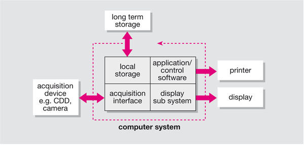
Fig 8-1 Standalone single-modality system, where the core functions of image handling are combined in one computer.
The second methodology is the “distributed” system (Fig 8-2), which has dedicated systems for each function. This allows multi-modality and multiple users to share the same system. This type of system is generically referred to as a picture archival and communication system (PACS) or mini PACS, and is usually installed in larger institutions.
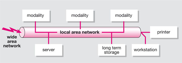
Fig 8-2 Distributed image handling, with dedicated systems for each function.
Regardless of the terminology or size, all these systems are effectively PACSs as they will archive and communicate pictures. Most systems will also use generic building blocks that are as applicable to a small system as they are to a larger one.
Medical Radiography Standards
The whole field of digital imaging in medicine is developing at an increasing rate, not only with respect to the modality and associated technologies but also with respect to the development of standards. Two standards are currently key to the integration of medical imaging systems; the Digital Imaging and Communications in Medicine (DICOM) and the Health Level Seven (HL7) standards.
DICOM
What is DICOM? DICOM is a ratified standard from the American College of Radiologists (ACR) and the National Electronics Manufacturers Association (NEMA) that aims to standardise connectivity in medical imaging. The need for this arose with the advent of digital imaging where each manufacturer would have their own method of connectivity and image storage. The current level of DICOM is version 3 although this is a little misleading as the previous version was called the ACR/NEMA standard 2.0. Additionally, although version 3 was released in 1993, there are frequent additions to the DICOM standard by the use of supplements. Most, if not all, manufacturers of medical imaging equipment now adhere to DICOM version 3. This does not, however, ensure compatibility of equipment, and terms such as “DICOM compatible” and “DICOM enabled” may be erroneous. DICOM at the technical level is quite complex; the perception that DICOM specification is difficult is further enhanced by DICOM conformance statements, which are impenetrable technical documents often issued at the tender stage by manufacturers and not really appropriate for clinical end users. This section aims to demystify DICOM and provide a practical level of knowledge to assist in purchasing decisions and in the day-to-day use of DICOM modalities. For those who wish to learn more about DICOM there is an official DICOM website (http://medical.nema.org), and the website of David Clunie is an excellent DICOM resource: (http://www.dclunie.com).
DICOM service classes
The service classes can be thought of as the DICOM communications protocols. They specify the levels of connectivity between modalities. The seven most useful classes for medical imaging are:
-
Verification
-
Modality Work List
-
Performed Procedure Step
-
Store
-
Storage Commit
-
Print
-
Query/Retrieve.
Not all these classes may be available on all modalities, and may be conditional on whether the service class is being used or provided by the modality. With each DICOM communication, a communication exchange is set up; where one system is the user and the other the provider. Therefore, in specifying DICOM service classes you have to decide your role: whether you just want to use that service (service class user – SCU), provide it (service class provider – SCP), or both.
An example of a DICOM communication would be where a modality wants to store an image on another modality: the sender will have to have DICOM Store at the SCU level and the receiver will have to have DICOM Store at the SCP level.
The sender could also receive images to store, but this would be a separate communication and would require DICOM Store SCP as well. A list of the service classes and the user/provider context is shown in Table 8-1.
| Service class role | ||||
| SCU | SCP | SCU and SCP | ||
| DICOM service classes | Verification | Can check to see if a DICOM communication is possible on another system | Can accept a DICOM communication check request to provide the required service | Can check and confirm that DICOM communications are possible |
| Modality work list | Radiological information system (RIS) – sends a work list to the modality | Modality – can receive work lists from the RIS | N/A | |
| Performed procedure step | Modality can send confirmation to the RIS that an examination is complete | RIS – can receive confirmation that an examination is complete | N/A | |
| Store | Can send images to storage | Can receive images to store | Can send and receive images to storage | |
| Storage commit | Can transfer ownership of images to the store modality | Can take ownership of images from the send modality | Can assign or receive ownership of images with another modality | |
| Can send images to print | Can receive images to print | Can send and receive images to print | ||
| Query/ retrieve | Can query a remote database and retrieve images from it | Allows its database to be queried and images retrieved | Can query and retrieve from another database and allows others to query retrive its own database | |
DICOM object
The DICOM object is the part of DICOM that contains the image data. This will contain not just the images but also all other modality-specific information to ensure the receiving system knows how the image is formatted and presented. There are many DICOM objects, and new ones are being added all the time. The current list includes, for example:
CR = computed radiography
CT = computed tomography
MR = magnetic resonance
NM = nuclear medicine
US = ultrasound
RG = radiographic imaging (conventional film/screen)
DX = digital radiography
MG = mammography
IO = intraoral radiography
PX = panoramic x-ray.
From this list it can be seen that dental-specific modalities are included. In many respects, the end-user does not need to be concerned with this level of DICOM other than to ensure that the relevant service class, roles and object are supported. This can be specified by using the DICOM service object pair (SOP).
DICOM service object pair
We have defined the service class, the service class role and the object; we can now use these to specify the exact DICOM functionality of the modality using the DICOM SOP. The SOP should be stated in a modality specification and used to establish levels of DICOM communication. An example would be a simple digital x-ray unit that can store to PACSs only.
The SOP for the modality would be:
| Service class | Role | SOP |
| Store | SCU | DX |
whereas the SOP for the PACS would be:
| Service class | Role | SOP |
| Store | SCP | DX, US, MR, CT, etc. |
The end-user looking at these SOPs can see that the two systems are compatible for the purpose of DICOM Store.
Modality configuration
The preceding sections dealt with the theory and specification of DICOM connectivity. An equally important element is the physical set-up of the modalities. Each modality has to be uniquely identified on the network. This is achieved in three ways: the IP address, the Application Entity Title and the port number:
-
IP address. The IP (Internet Protocol) address is a unique four-part numerical identifier. The range of IPs is unique for a particular network, and an individual unique IP is issued by the network administrator for each modality. A typical IP could be 192.168.120.5; IP addresses are covered in more detail in the section on networking.
-
Application entity title (AET). The AET is effectively the name of the modality on the network. A usual syntax would be AET_MXRRM1; which stands for main x-ray (MXR) room 1 (RM1). AETs can be extremely useful in administration tasks as they allow modalities to be identified without the need to refer to lookup tables. However, ambiguous AETs, such as AET_A012DFRZ1, can cause delays in fault finding, particularly on large systems. Additionally, errors can be introduced in having to retype complex AETS, as these may need to be entered on all devices that the modality needs to connect to. Some DICOM modalities allow verified DICOM identities to be turned off. This allows them to accept any DICOM connection, which can be advantageous in some cases, but in general verified DICOM identities are preferable.
-
Port number. Computers connected to a network have a number of virtual ports that they can access (see the section on networking). These can be thought of as numbered subconnections on the computer. If a port is closed, no connection is available. Additionally, if the software is listening to the wrong port, it will not recognise when a DICOM communication is taking place. Therefore, the correct port, which has been specified in the local DICOM settings, must also be specified on other modalities. It does not matter which port number is used as long as it is specified at both ends of the communication. Ports 104 and 4006 are often used for DICOM purposes; one model could use port 104 for workstations and port 4006 for modalities, or 4006 for all DICOM devices.
DICOM greyscale standard display function (Part 14)
There are additional DICOM components that are of a more specialised nature and not of interest to the general reader. However, one additional component is essential to the correct display of images: the DICOM greyscale standard display function (GSDF).
There is a huge choice of commercial displays, each with its own characteristics. This is not helpful for viewing medical images, as an image on one monitor may appear completely different on another monitor. The DICOM GSDF was defined in an attempt to standardise image display. The GSDF describes the non-linear human perceptual response to different levels of luminance. It is based on a model of the human visual system and defines a standard curve against which different types of display devices can be calibrated. In this way, the calibrated image display uses the available contrast of the display device in a “perceptually” linear way (i.e. the difference between black and 5% grey is perceived equal to the difference between white and 95% grey). This calibration can yield a consistent image display, which means that the appearance of the image to the human observer is as similar as possible given the differing properties of display devices.
To set up the DICOM display function correction requires the measurement of the characteristic curve of a display system. This is done using a number of uniform images with areas of constant grey level from black to white and a photometer. A lookup table (LUT) is generated by mapping each point on the GSDF curve to the closest point on the measured curve. This LUT is then used to map the measured characteristic curve to the GSDF. This task can often be conducted automatically on high-end monitors, and lower specification monitors often have built-in DICOM curves applied.
Health Level Seven (HL7)
Although DICOM is a key component in a PACS, the system still requires integration with the patient management system to ensure that images are unambiguously linked to the correct patient. This is achieved using information system standards such as HL7.
HL7 is a standard that is accredited by the American National Standards Institute (ANSI) to provide a standardised method of interfacing hospital information systems. This is very much a standard for system integrators and developers, and for the large part the clinical user will be unaware of HL7 except when procuring information systems or PACSs. However, it is a pivotal component in PACSs as it ensures consistency of data, theoretically all the way from the hospital information system (HIS) or practice management software, through to the radiological information system (RIS) – in larger institutions – and through to the modality. This then ensures that any image data acquired at the modality is intrinsically linked to high probity demographics from the initial booking stage.
This has two major benefits; first, workflow at the modality is faster as the patient will automatically be listed through DICOM work lists, making entry of data at the modality unnecessary; and second, the instances of unvalidated images will be reduced or eliminated. Unvalidated images can occur if patient demographics are incorrectly entered at any stage; for example, if a patient’s correct name is “Stephens” but at the modality it is spelt “Stevens” there will be a mismatch of the data. This can result in either the data being rejected by a PACS, as it will not match the HIS data, or duplicate entries being generated for the same patient. As a result, either the images will not be available to view, until they are manually fixed to the HIS database, or only some or no images will be retrieved when searching for the patient on the image database at a later date.
Networking
A major component in any digital image system, particularly with multi modalities and workstations, is the network.
In a multi-surgery dental practice there may be several computers and associated x-ray systems, linked by a network. A computer network is not just the physical connection between computers, it also includes the communication protocols running on it. The following is a simple introduction to the most common components and terminology encountered in setting up a digital imaging network. The basic principles will be the same, from a simple peer-to-peer, computer-to-computer connection through to a hospital-wide corporate system. There are many sources of information on networking, including the Internet, and the UK MHRA Evaluation Centre PACSNet has produced a useful background document for healthcare users in the UK (see Further Reading).
There are two general categories of network, t/>
Stay updated, free dental videos. Join our Telegram channel
VIDEdental - Online dental courses


