Chapter 3
Panoramic Equipment and Imaging
Aim
The aim of this chapter is to describe modern panoramic x-ray equipment, in particular those design features that improve safety and image quality.
Outcome
After reading this chapter the reader should be able to:
-
give the indications for panoramic imaging
-
list the functions of components of a panoramic machine
-
outline how a panoramic image is formed
-
describe how to position a patient correctly in a typical machine
-
assess image quality
-
identify common anatomical structures
-
outline the additional features and programmes that are found on modern panoramic units.
Indications for Panoramic Imaging
The panoramic radiograph has several advantages over intraoral imaging. It is quicker and easier to perform than a set of full-mouth periapical views, and because all teeth and supporting structures are shown on one film it has an ancillary use for patient education.
There used to be a dose advantage in using a panoramic view over a set of full-mouth periapical views. However, using modern intraoral equipment and techniques this may no longer be the case. In addition, the resolution of the panoramic image is lower than obtained by intraoral imaging. The indications for panoramic imaging are limited to those situations where intraoral imaging is not practicable or realistic. This makes it ideally suited to the evaluation of large intrabony lesions, impacted third molars, the assessment of bony trauma and assessment of the bony parts of the temporomandibular joints.
In the general practice setting, panoramic radiography should not be used as a screening tool for new patients, as the prevalence of significant asymptomatic disease is low. The following indications for panoramic imaging are taken from Selection Criteria for Dental Radiography, a document published by the Faculty of General Dental Practitioners (UK):
-
Where a bony lesion or unerupted tooth cannot be demonstrated on intraoral radiographs.
-
In a patient with a neglected dentition where clinically there are multiple carious teeth and there is concurrent generalised advanced periodontal disease.
-
As part of an orthodontic assessment where there is a clinical need to know the state of the dentition and the presence or absence of teeth. (In addition, the British Orthodontic Society has produced guidelines on the use of radiographs in orthodontics.)
-
In the assessment of third molars prior to surgical extraction.
Equipment
A typical panoramic machine and its components are shown in Fig 3-1.
-
X-ray tube head. Produces the x-ray beam. The beam is aimed slightly upwards, towards the slot in the cassette holder.
-
Diaphragm. The x-ray beam is collimated by the diaphragm to form a vertical slit-shaped beam. The x-ray beam width should be no greater than 5 mm.
-
Cassette holder. Has a metal sheet at the front that prevents scattered x-ray photons reaching the cassette, which would otherwise degrade the image. There is a narrow vertical slot in the holder directly opposite the x-ray source. This ensures that only a small amount of the film is exposed at one time.
-
Cassette carriage. Moves the cassette behind the cassette holder during the exposure.
-
Bite block. Used to locate both upper and lower incisor teeth in an edge-to-edge relationship in the focal layer. It also separates the upper and lower teeth to prevent overlap.
-
Light-beam markers. Used to position the patient correctly, to ensure that the teeth fall in the focal layer.
-
Head-holding apparatus. Allows the patient’s head to be immobilised once accurately positioned.
-
Handles. Minimise movement of the patient.
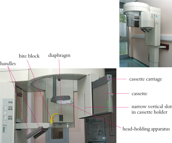
Fig 3-1 An example of a panoramic machine, with the main components labelled.
Image Formation
Simultaneous rotational movements of the x-ray source, cassette and cassette-holder in the horizontal plane produce a U-shaped focal layer of the teeth and jaws. During the exposure, the x-ray beam moves behind the patient, the cassette holder moves in front of the patient, and the cassette carriage and cassette move behind the slot in the cassette holder. These movements are shown in Fig 3-2.
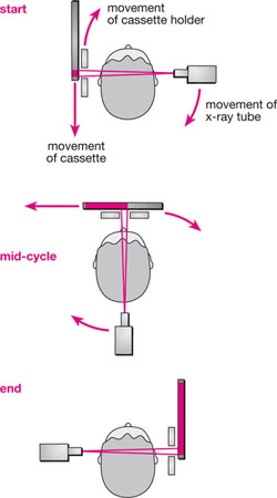
Fig 3-2 Diagram showing the movements of the x-ray tube, cassette holder and cassette during a panoramic exposure. (Based on a diagram provided by Mr E Whaites).
The x-ray beam passes through the structures in the focal layer at the same speed as the cassette passes behind the slot in the cassette holder, ensuring those structures are sharply defined. The focal layer reflects the shape of the jaws in an “average patient”, but it varies in shape depending on manufacturer. The thickness of the layer also varies; being narrower anteriorly than it is posteriorly. Some units use a continuously moving centre of rotation to produce the U-shaped focal layer (Fig 3-3). It should also be appreciated that the focal layer is three dimensional, with the height of the layer being determined by the height of the slit-shaped beam.
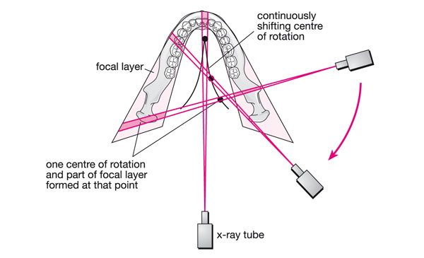
Fig 3-3 Some machines use a continuously moving centre of rotation to produce the curved focal layer similar in shape to the “average jaws”. This diagram shows three stages in this movement, the position of the x-ray tube and direction of the x-ray beam at these times, and the part of the image formed at these stages.
The image is magnified by between 10 and 30%. Magnification in the vertical and horizontal planes is equal only for those structures that fall into the centre of the focal layer. Therefore, uniform magnification of the teeth is seen only when the patient is positioned correctly and the shape of the jaws conforms exactly to the shape of the focal layer. Those structures outside the focal layer are distorted, blurred and often unrecognisable. Those structures that fall between the focal layer and the cassette tend to be narrowed in the horizontal plane and those structures located lingually are magnified in the horizontal plane. Distortion in the vertical plane is not generally as marked as in the horizontal plane. Some studies have shown that there can be a narrowing of the focal layer if it is captured digitally, making patient positioning even more important.
The image is built up sequentially as the apparatus rotates about the patient, with an exposure time of 12–20 seconds for an adult. It is vitally important that the patient remains motionless during the exposure, to prevent movement artefacts on the image.
Procedure
Before the Exposure
-
Confirm the identity of the patient.
-
Ask the patient to remove dentures, removable orthodontic appliances, tongue studs, earrings, necklaces, glasses and hair ornaments which may be in the path of the x-ray beam.
-
Set a suitable programme and exposure factors.
-
Place a plastic sleeve on the bite block for control of cross-infection purposes.
Stay updated, free dental videos. Join our Telegram channel
VIDEdental - Online dental courses


