Chapter 2
Intraoral X-ray Equipment and Imaging
Aim
The aim of this chapter is to describe modern intraoral x-ray equipment, in particular those design features that improve safety and image quality.
Outcome
The reader should be able to:
-
recognise the key features in modern intraoral x-ray equipment
-
explain the safety design features of modern intraoral x-ray equipment
-
explain how the design features of the x-ray set can affect image quality
-
relate safety and image quality to current regulations and good practice guidelines.
Components of an Intraoral X-ray Set
Various components make up an intraoral dental x-ray set, the functions of which are shown in Table 2-1. A typical intraoral set is shown in Fig 2-1.
| X-ray tube head | |
| Component | Function |
| X-ray tube | Site of x-ray production |
| Tube head housing | Metal casing that helps prevent leakage of radiation. It is filled with oil to help dissipate the heat generated during x-ray production |
| Step-up transformer | Steps up the voltage applied across the x-ray tube from 240 V to between 60–70 kV |
| Step-down transformer | Steps down the voltage applied to the filament to 10 V |
| Autotransformer | Allows the kV to be varied on those sets with variable kV selection |
| Aluminium filter | Filters out low-energy x-ray photons |
| Collimator | Metal component that defines the size and shape of the x-ray beam |
| Position indicating device (PID) | Device that allows the beam to be aimed accurately at the area under investigation and also sets up the focus-to-skin distance |
| Extension arm | |
| The arm allows precise and steady positioning of the x-ray tube head so that the position indicating device may be aligned correctly | |
| Exposure control panel and exposure button | |
| The panel allows the setting of the exposure time. The milliamperage (mA) is normally fixed by the manufacturer and is not adjustable. Some machines allow the operator to adjust the kV. Once the exposure factors have been set, pressing the exposure button activates the exposure. | |
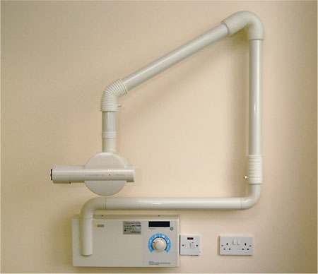
Fig 2-1 An example of a modern intraoral x-ray set.
The X-ray Tube
The x-ray tube is composed of an evacuated glass tube containing a cathode (tungsten filament) and an anode (tungsten target set into a copper stem). A low current, typically around 7 mA, is passed through the tungsten filament, producing a cloud of electrons by thermionic emission. A focusing cup surrounding the filament keeps the electrons near to the filament. The electrons are then accelerated towards the tungsten target by the high potential difference (60–70 kV) between the cathode and the anode. The electrons are travelling fast when they strike the focal spot in the target and rapidly lose their kinetic energy in the form of heat and x-ray photons. The heat is conducted away from the tungsten target by the copper stem and is further dissipated by the surrounding oil. The x-ray photons pass through the thin glass tube. The components of the x-ray tube are shown in Fig 2-2.
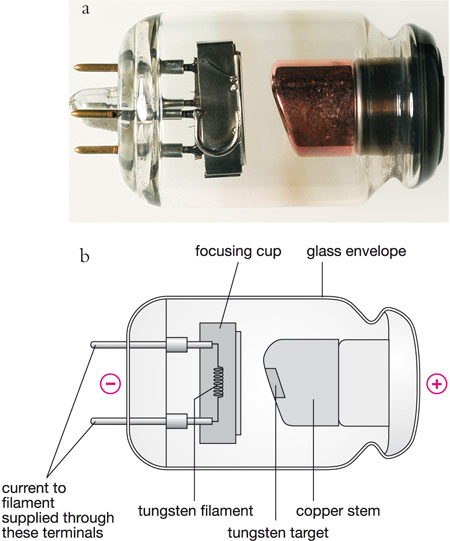
Fig 2-2 a) The dental x-ray tube; b) The main components in the x-ray tube.
Recommendations for X-ray Equipment
In the UK, intraoral dental x-ray sets are designed and constructed so that they comply with British Standards and meet the safety and performance standards set out in the Medical Devices Regulations 1994. In the USA, all x-ray machines have to comply with performance standards set out by the Food and Drug Administration in 1995. Similar regulations are found in other countries.
Although the dose from one intraoral exposure is low, intraoral radiography is one of the commonest x-ray investigations undertaken in both the UK and USA. Therefore, the principle of “optimisation” should be followed at all times – keeping the radiation dose as low as reasonably practicable. Modern intraoral equipment incorporates many dose saving design features, the requirements for which include the following:
-
New equipment should operate at a high kilovoltage.
-
Constant potential units are superior to alternating current x-ray sets.
-
The x-ray tube, x-ray housing and position indicating device should be constructed to keep radiation leakage to a minimum.
-
Adequate filtration of the x-ray beam should be employed.
-
Open-ended position indicating devices should be used in conjunction with rectangular collimation.
-
The position indicating device should provide a long focus-to-skin distance.
Kilovoltage
The kilovoltage refers to the potential difference applied across the x-ray tube. Strictly speaking, the term “kVp” (peak kilovoltage) should be used as this reminds us that the stated kilovoltage is that achieved at the peak of the alternating potential provided by the mains electrical supply. For simplicity, this book uses the term “kV”. If a high kV is selected, the electrons in the x-ray tube are accelerated more and will be travelling more rapidly when they hit the target. The interaction of these electrons with the tungsten target will produce higher energy x-ray photons. Higher energy photons have shorter wavelength and are more penetrating. Therefore, these photons are less likely to get absorbed, decreasing the skin dose. A kV of between 60 and 70 kV is generally recommended.
However, the kV also has an effect on the quality of the image, in particular the radiographic contrast. The relationship between patient dose and radiographic contrast is discussed later.
Constant-potential Units
As indicated above, the mains power supply is alternating potential, and hence alternating current (AC). This means that the current is continuously oscillating from positive to negative. Each complete oscillation is known as a cycle. The number of cycles per second will vary depending on the country; there are 50 cycles per second (50 hertz) in the UK and 60 cycles per second (60 hertz) in the USA.
The mains voltage follows a similar waveform to the current (Fig 2-3). Only the positive half of the cycle is useful in producing x-rays. Rectification circuits ensure a positive kV is always applied across the tube.
-
In full wave rectification, there are 100 pulses per second (in the UK), but peak voltage is only achieved for a short period of time. For the remaining time the kV is lower, producing lower energy x-ray photons. These lower energy photons increase the />
Stay updated, free dental videos. Join our Telegram channel
VIDEdental - Online dental courses


