Chapter 4
Conventional Image Receptors
Aim
The aim of this chapter is to describe the modern choices available for the clinician using traditional image receptors for x-ray imaging.
Outcome
After completing this chapter, the reader should have an understanding of:
-
the modern choices for non-digital capture of intraoral x-ray images
-
the modern film/screen/cassette combinations available for extraoral radiography
-
the modern choices for processing film-based images.
Intraoral Dental Film
While digital radiography is fast becoming the 21st-century option for dentists, it is likely that conventional film will remain the modality of choice for many dentists for economic reasons. By conventional film, we mean the direct x-ray sensitive film that is used for intraoral radiography. Only dentists use this type of film, with intensifying screen/film/cassette combinations used in all other types of conventional (non-digital) radiography. There are several reasons for this. Constructing tiny cassettes for use in the mouth is expensive and demanding. The challenge of cross-infection control means that disposable film packets are a convenience. It is, however, also important to remember that direct x-ray sensitive film offers a much higher resolution than do screen/film/cassette combinations (Fig 4-1).
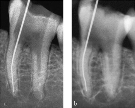
Fig 4-1 Two radiographs of the same tooth, taken a) using conventional, direct x-ray sensitive, intraoral film and b) using a screen/film/cassette combination. The intraoral film gives much better resolution, while the cassette film image shows some blurring in comparison.
Over the past century, there has been a steady pace of development in dental film technology, aimed principally at reducing the exposure necessary to produce the required “blackening” (optical density). The relationship between exposure and density is demonstrated by the film characteristic curve shown in Fig 4-2, which allows a simple visual method of relating a film’s “speed” and “contrast”. Films can be classified into groups, using capital letters as the group indicator. Until 1980 the fastest film commercially available was film of group D speed. This was superseded by E-speed film in 1981. This film could give the same density for about 50% of the exposure needed with D-speed film.
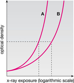
Fig 4-2 Film characteristic curves for dental x-ray films. Optical density (vertical axis) indicates the “darkness” of the film. For the same density, film A requires less exposure than film B. Film A is, therefore, the faster film.
However, the E-speed film had a lower inherent contrast and greater sensitivity to aged and depleted processing solutions, which led to resistance to its adoption by many dentists. Furthermore, the very fact of it being “faster” meant that less than satisfactory darkroom safelighting might produce a significant fog level, which did not occur on the slower D-speed. Subsequent developments in film technology produced improved E-speed emulsions and, most recently, films that fall into the F-speed group. Relative speed varies a little between manufacturers, but the change to F-speed film can allow 20–25% lower exposures than the same manufacturer’s E-speed product.
The modern dentist who still uses conventional radiography should, therefore, use film speeds from the F-speed category. There is, however, an occasional barrier to this because the x-ray set cannot be easily adjusted to reduce exposures. As might be expected, this is particularly so for older machines. In such instances it is sensible to discuss the problem with your x-ray engineer and (in the UK) radiation protection adviser.
One final point worth mentioning is the use of “instant process” film. A number of manufacturers produce film that can be processed very quickly using a “monobath” solution, injected directly into the film packet. The films are, at best, D-speed, and image quality is invariably poorer than could be achieved with conventional processing. Therefore these should not be used for routine radiography. At best, their role would be in emergency situations, such as out-of-hours work when it is impracticable to organise normal processing, or during surgical procedures when a very rapid radiograph is needed.
Extraoral Radiography using Film Cassettes
Cassettes are used for panoramic, cephalometric and oblique lateral radiography. These are far more than simple rigid containers for a large film. Essentially, they include three different components:
-
the outer casing
-
a compressible layer
-
the intensifying screens.
This arrangement is duplicated on either side of the hinged cassette shown in Fig 4-3 and is shown diagrammatically in Fig 4-4. The outer casing does, indeed, act as a container for the film and should be light-tight. A rigid cassette design is preferred as this is more robust and gives image quality advantages. Flexible cassettes, sometimes provided by manufacturers of panoramic x-ray equipment, are prone to light leaks (Fig 4-5) and poor film-screen contact (Fig 4-6).
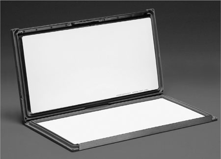
Fig 4-3 A radiographic cassette, showing one intensifying screen on each side.
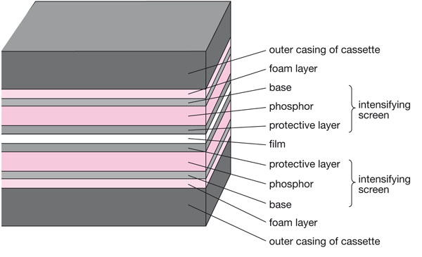
Fig 4-4 A diagrammatic cross-section of a closed cassette containing a film. The film is sandwiched tightly between opposing screens.
These are typical of light leakage into the cassette causing localised film fogging.
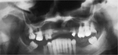
Fig 4-5 This poor-quality panoramic radiograph shows dense (black) artefacts along the upper edge of the film.
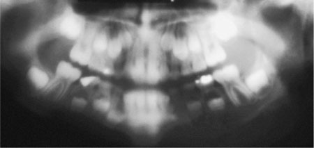
Fig 4-6 Poor film-screen contact results in considerable image unsharpness as light emissions from the screens diffuse before reaching the film.
The most important components in the cassette are the intensifying screens. These come in pairs; one is fixed to each side of the cassette. The film is placed between the screens. Intensifying screens work by absorbing the x-ray energy and converting it to light (fluorescence), which in turn exposes the film. Using intensifying screens rather than film alone allows x-ray exposures to be reduced enormously (by at least 90%).
The base material of the intensifying screens is a thin plastic layer, which supports the x-ray sensitive phosphor coat. It also helps in the imaging process by reflecting light from the phosphor on to the screens. In some cases this reflection is a property of the base material itself, and in others it is produced by a coating of titanium dioxide.
There are basically two types of screen: calcium tungstate and rare earth. The former has a long history, while the latter was first introduced in 1972. Calcium tungstate fluoresces at 440 nm (blue light). Many dental practices probably still use cassettes with this type of phosphor, but calcium tungstate absorbs x-rays and converts their energy to light very inefficiently. The alternative rare earth phosphors work far more efficiently. They vary in composition from manufacturer to manufacturer, but those used most frequently contain:
-
gadolinium oxysulphide (terbium activated)
-
lanthanum oxybromide (terbium activated)
-
yttrium tantalite (niobium activated).
The first two of these emit light in the yellow/green end of the spectrum, while the third emits blue/>
Stay updated, free dental videos. Join our Telegram channel
VIDEdental - Online dental courses


