Chapter 7
Indirect Digital Imaging
Aim
The aim of this chapter is to provide a comprehensive understanding of indirect digital x-ray imaging in dentistry.
Outcome
After reading this chapter the reader should be able to:
-
describe the basic construction of a photostimulable phosphor plate
-
explain how a typical indirect digital system works
-
give the advantages and disadvantages of these systems.
What Does Indirect Digital Radiography Mean?
There is some confusion in the use of the term “indirect digital imaging”. To some this means digitising a conventional radiograph using a flatbed scanner with a transparency adaptor. In this chapter, the term is used for images acquired using a photostimulable phosphor plate (PSP).
With these systems, once the PSP has been exposed the sensor has to be scanned by a laser before the image can be displayed. As there is this additional scanning process, these systems are referred to as indirect digital systems.
Principles of Indirect Digital Radiography
Construction of the PSP
The PSP is similar for all systems and comprises:
-
a phosphor layer
-
a reflective layer
-
an electroconductive layer
-
a polyester or polyethylene base layer
-
a light-shielding layer
-
protective layers.
A cross section of a PSP illustrating these layers and their functions is shown in Fig 7-1. A PSP will last for several thousand exposures, so long as it remains undamaged and free of scratches.
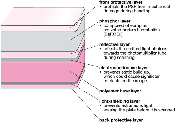
Fig 7-1 Cross section through a typical PSP showing the layers and their functions.
Interaction of the Phosphor Layer with X-radiation
When exposed to x-radiation, photoelectric interactions within the phosphor layer produce photoelectrons, which remove electrons from the europium activator. These electrons become trapped within fluorohalides at sites known as “F centres”, leaving “holes” at the original europium sites. Some of the electrons drop back almost immediately, but importantly, the remaining electrons stay trapped within the F centres.
The number of trapped electrons at any particular point on the PSP is proportional to the original number of x-ray photons incident on that part of the sensor, thus producing a latent image.
Scanning the PSP and Displaying the Image
The PSP with the stored latent image is scanned immediately using a thin red helium–neon laser beam. The laser energy causes the electrons to fall back into the europium holes, emitting light from the blue part of the visible spectrum. This process is known as “photostimulable luminence”.
The blue light is detected by a photomultiplier tube (PMT). The PMT produces an amplified voltage proportional to the original light received. The voltage is converted into a digital signal by an analogue–digital converter (ADC). The ADC may have an output as high as 32 bits, which corresponds to over 4 billion grey level values. Because the human eye cannot perceive this many grey levels, the image is normally displayed with 256 shades of grey (8 bits).
Various scanning methods are employed, including the following:
-
Linear scanning. The PSP is simply moved in front of a fixed laser source. The laser beam is deflected by mirrors onto the surface of the PSP. The Digora FMX and Optime (Soredex, Tuusala, Finland) use technology based on linear scanning.
-
Carousel/drum scanning. The PSP is secured to a carousel, which rotates as the imaging head containing the laser moves down, parallel to the drum. The DenOptix (Gendex Dental Systems, Lake Zurich, USA) employs this method of scanning.
-
Spinner scanning. The laser beam rotates while the PSP moves downwards. The laser is transmitted via a pentaprism onto the PSP. The blue light produced is reflected by parabolic mirrors onto the photomultiplier tubes. The VistaScan (Dürr Dental, Beitigheim-Bissingen, Germany) employs spinner-type technology.
These scanning processes are shown in Fig 7-2 and examples of the equipment are shown in Fig 7-3.
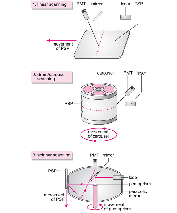
Fig 7-2 Diagram showing the scanning processes that may be employed by the indirect digital imaging systems; a) linear scanning; b) drum/carousel scanning; c) spinner scanning.
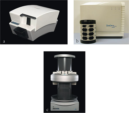
Fig 7-3 Examples of indirect digital imaging systems; a) Digora Optime, utilises linear scanning; b) Gendex DenOptix, utilises drum/carousel scanning; c) Dürr VistaScan, utilises spinner scanning.
Scanning times vary between systems. In addition, the scanning time may depend upon the scanning resolution selected, the size of the sensor being scanned and the number of sensors that require scanning. This time may be as short as 10 seconds for a single intraoral sensor, but for a “high-resolution” panoramic image it may be as long as 5 minutes.
Erasing the PSP
The Digora systems automatically erase the PSP during the scanning process, leaving it ready for immediate reuse. However, with the VistaScan and DenOptix systems a latent image remains after scanning. This is because some of the electrons still remain within the F centres. Therefore, the sensor needs to be erased before being used again, otherwise a “double image” is produced. Erasure may be achieved by placing the PSP on a conventional light box. The time taken to erase the PSP will depend upon the intensity of the light produced (1000–5000 lux) but it should be cleared and ready for reuse in under 2 minutes. The PSP may also be erased using the manufacturer’s dedicated erasure system.
A flow diagram showing these stages is given in/>
Stay updated, free dental videos. Join our Telegram channel
VIDEdental - Online dental courses


