Chapter 8
Delayed Placement in Adequate Bone with Mature Ridge
Introduction
Delayed insertion of implants into mature bone of adequate width and height is a very safe and predictable technique with which to achieve osseointegration. It enables the clinician to select the implant site with precision and to be assured of the attachment of bone to the implant.
An extraction socket matures at approximately six months, confirmed by radiographic assessment. This provides a healed bony site where an osteotomy can be prepared. This can be predicted by proper assessment of the bony biotype. Other techniques have been described to commence treatment at completion of soft tissue healing and often require advanced surgical techniques using membranes and biomaterials to correct any deficiency that naturally would be present. These techniques are described elsewhere.
Typically in situations where malpositioned teeth need to be replaced, allowing the extraction site to heal will permit implant site selection to match the proposed ideal tooth position as predicted based on bone biotype (see Case 4, below). Carrying out treatment in stages also permits bone deficiencies caused by infection to be repaired naturally. This in specific biotypes permits implant placement without the need for augmentation. In other cases staged treatment allows the clinician to confirm the need for augmentation based on a visual assessment of the provisional restoration and a radiographic assessment of the bone volume (Case 4 in Chapter 14).
Furthermore, the bone level on the completion of healing and remodelling can be predicted specific to the implant system used. For example, for an externally hexed system, the minimum interimplant distance has been specified as 3 mm.103 This was based on the expected remodelling of bone resulting from micro-leakage at the implant–abutment interface. Other systems that have an implant–abutment junction with no micro-gap are beginning to redefine the minimum interimplant distance.119
For a 3.5-mm implant, a minimum ridge height of 12 mm and a minimum width of 6 mm is considered necessary (Figs 8-1 and 8-2). This will leave more than 1 mm of residual bone on the buccal and lingual aspect of the ridge. The length of the ridge for a single tooth should ideally be 8 mm and 14 mm for two implants of the above diameter (Figs 8-2 and 8-3; Flowchart 8-1).
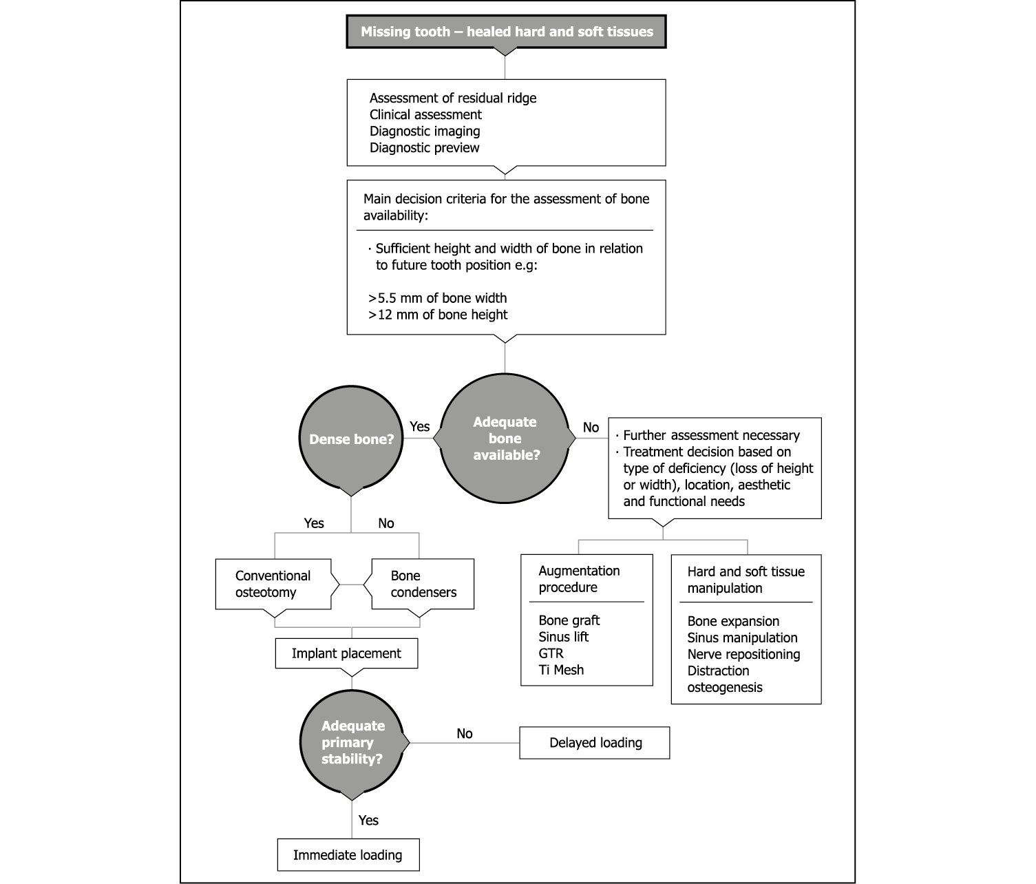
Flowchart 8-1 Ridge assessment for delayed placement in healed site.
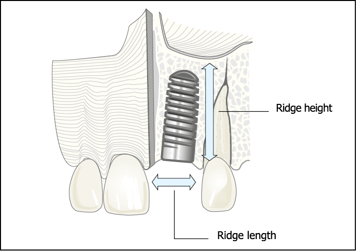
Fig 8-1 Schematic representation of an implant placed to replace the maxillary left central incisor. The ridge length (L) represents the distance between the adjacent teeth. The ridge height (H) represents the height of alveolar ridge available for an implant and corresponds to the length of an implant that could be used.
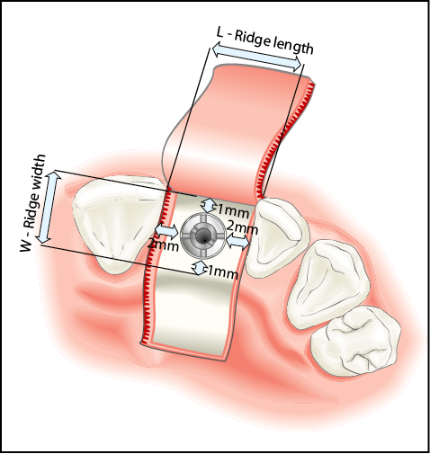
Fig 8-2 Schematic of the occlusal view of the implant showing the ridge length (L), which has an impact on the implant diameter. The width of the ridge (W) determines the diameter of the implant that can be used. The ideal ridge length and width have been estimated based on the most common implant diameter (approximately 3.5 mm). The estimated ridge length allows for up to 2-mm clearance from adjacent teeth and the minimum ridge width allows for 1-mm thickness of bone on both the buccal and palatal sides of the implant.
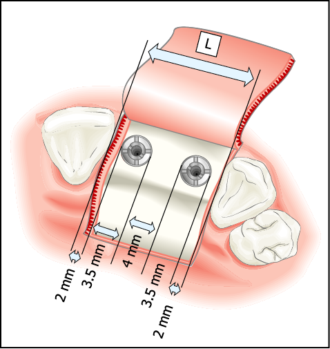
Fig 8-3 The estimated minimum ridge length for two implants placed interdentally. A space of 15 mm is considered suitable allowing 2-mm clearance between the adjacent teeth and implants and a 4-mm clearance between the two implants.
Delayed placement in mature bone offers the opportunity to load an implant immediately at the time of placement. Assessment for this is carried out in the preoperative phase, as the requirements in terms of the surgical approach, component parts and the transitional restorations will differ (Flowchart 8-2).
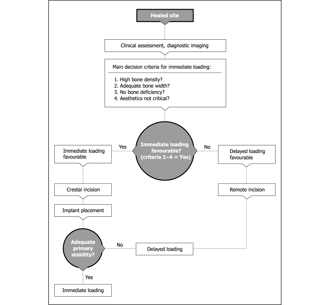
Flowchart 8-2 Assessment for delayed or immediate loading.
Assessment
Clinical Assessment
The clinical appearance of the ridge height and width should be assessed (Figs 8-4 and 8-5). The ridge height should be compared with the papillary height of the adjacent teeth. The width should be assessed in relation to the labial contour around the adjacent teeth. The gingival margin and the height of the papillae should be noted, because scalloped thin papillae are more difficult to reproduce than flat and thick papillae (see Figs 6-6 and 6-7, p. 34).
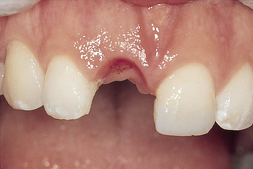
Fig 8-4 Preoperative labial view: the gingival contours can be seen following the removal of the provisional restoration.
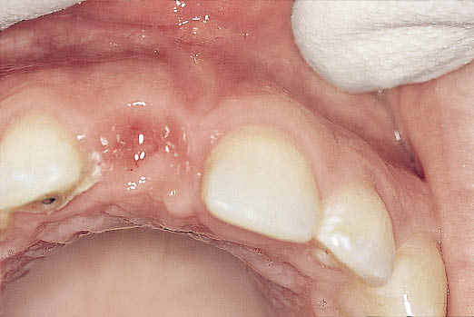
Fig 8-5 Occlusal view showing adequate width of the residual ridge.
Although the height and width of bone can be assessed using radiographic means (CT) or ridge mapping, the relationship of the ridge to the future tooth requires assessment. This can be achieved accurately by positioning a tooth in the desired position and noting the projected gingival contours (Fig 8-6).
Fig 8-6 Metal-acrylic resin Rochette bridge replacing the maxillary right central incisor demonstrating excessive tooth length.
The number of missing teeth will also have a bearing on the treatment outcome; consequently the length of the ridge (e.g. mesiodistal space) in relationship to the number and size of the teeth will influence the treatment plan. The precise location of the implant site will influence the emergence profile, the interdental bone height and the soft tissue contours.
Radiographic Assessment
Periapical Radiograph
Periapical radiographs are valuable for establishing the status of healing following tooth loss and for the elimination of any pathology. Any residual roots or pathology can be identified on the radiograph. The interdental ridge height as well as the bone level at the proposed implant site can be measured in relation to the cementoenamel junction of the adjacent teeth.
An impression of the ridge width can be gained by trabecular density, although this cannot be relied on. Relevant anatomical structures (e.g. naso-palatine canal or the inferior alveolar canal) and their proximity to the implant site can be estimated from a periapical radiograph.
The height of the available bone can be accurately assessed using techniques where the distortion is known or minimal. The mesiodistal dimensions of the available bone and the space available between the adjacent roots and the orientation of the roots can also be determined using this type of radiograph (Figs 8-7–8-9).
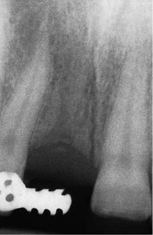
Fig 8-7 Preoperative periapical radiograph demonstrating adequate bone and local anatomy such as naso-palatine canal and proximity of roots.
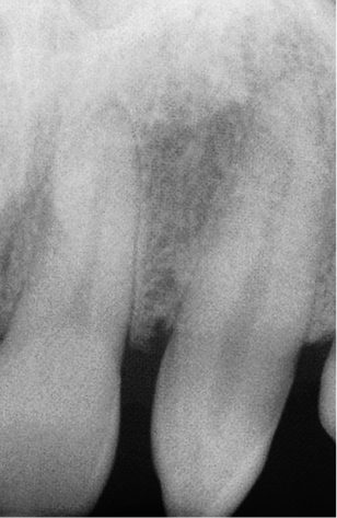
Fig 8-8 Preoperative periapical radiograph of the region requiring restoration, showing inadequate space for implant placement.
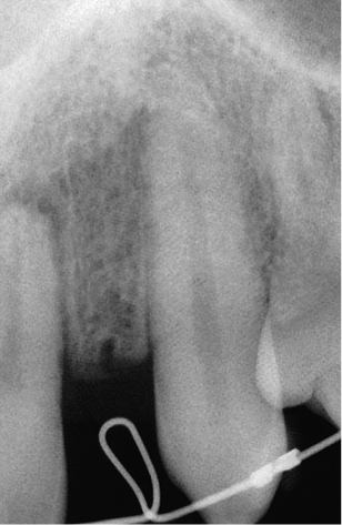
Fig 8-9 Periapical radiograph on completion of the orthodontic treatment, showing sufficient interdental space. (Orthodontics carried out by Dr Peter Gascoigne, London, UK.)
Dental Panoramic Tomography (Orthopantomography)
DPTs provide an excellent overview of the jaws, confirming the information obtained from periapical radiographs.
Computed Tomography
CT provides very useful 3D information regarding the spatial orientation of the ridge when the tooth position has been identified with markers of distinct radiopacity. Additional information relating to bone density measurements will facilitate the decision whether to load immediately or not. Furthermore, CT will provide guidance regarding techniques to be employed during surgery.
Preoperative Stage
Where there will be delayed insertion of an implant in a mature ridge, the following preoperative stages are considered pertinent to accurate assessment. Impressions of the mandible and maxilla, coupled with a facebow when required, can be used to provide the diagnostic and treatment aids described below.
Diagnostic Preview
The arrangement of acrylic resin denture teeth of the correct form on a baseplate in the ideal aesthetic and functional position can be used to assess the possible treatment outcome by transferring the preview to the patient’s mouth. Pink wax should not be used on the labial aspect, and flanges are contraindicated. An assessment of the tooth length can only be made when the tooth or tooth-coloured wax is used in contact with the soft tissues, providing a contrast to facilitate assessment.
The relationship of the ideal tooth form to the residual ridge can be used to establish the need for augmentation. A decision regarding the use of maxillary bone expansion or autogenous onlay graft to achieve the ideal ridge contour can be made in conjunction with appropriate diagnostic imaging techniques. Patients’ involvement in this assessment process is fundamental to informed consent. More effective feedback can be obtained by transferring this information into a fixed provisional restoration.
Diagnostic Template
On completion of the assessment, the information gathered can be transferred to a template constructed from the diagnostic preview.
The concept of a hollow prosthetic envelope to transfer the validated aesthetic and functional parameters to the surgical site is considered to be the most effective means of guidance during surgical phases.120 The diagnostic template may be used for a number of purposes:
- • positioning a bone graft to ensure insertion of an implant in the ideal position
- • confirming the implant site selected using established guidelines that take into account local anatomical parameters
- • selecting and confirming the abutment and its position within the prosthetic envelope to permit the proposed restoration
- • indicating any requirement for manipulation of the soft tissues to establish the desired contour.
Templates designed in the laboratory to guide the surgeon in the positioning of the implant are considered inappropriate and liable to cause surgical error, since anatomical details are not available to the laboratory. Furthermore, directional drilling guides built into templates by the laboratory without accurate guidance from 3D imaging are considered to be equally dangerous.
Drill Guides Based on CT Data
Guides may be fabricated based on accurate planning using interactive CT data-based computer software. The clinician is, therefore, responsible for selecting the precise implant position and angulation, using appropriate software. This is limited by the accuracy of the technology used. The ideal tooth position must also be transferred and visualised on the CT scan in order to accurately coincide implant and tooth position. The template should then be fabricated by direct and accurate means, such as stereolithography, using the data provided by the clinician. The template must be supported by a rigid structure, such as bone or teeth. If soft tissue support for the template is planned, additional fixation is recommended. However, the prerequisites for transmucosal (flapless) surgery are adequate keratinised non-mobile soft tissue in addition to adequate hard tissue. Artefacts from restorations might prevent accurate planning and further limit the use of this approach (see Fig 7-192, p. 99).
Provisional Restoration
Provisional restorations may be used to replace missing teeth during the phases of treatment. They serve the valuable purpose of providing verification for the established aesthetic design and occlusal scheme. Varying benefit can be gained depending on the type of restoration used.
Removable Dentures
Removable dentures should be made of acrylic resin to allow modifications to be easily made in situations where the ridge contour is altered. Limited diagnostic information is available for aesthetic assessment, particularly if flanges are used (Figs 8-10 and 8-11).
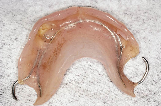
Fig 8-10 Partial acrylic resin denture with flange that requires replacement.
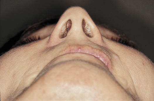
Fig 8-11 Extraoral view from caudal aspect of the patient without the denture demonstrating the loss of lip support.
Furthermore, dentures are inherently unstable and provide little information with respect to function. They pose an increased risk when used during augmentation procedures.
Conventional Bridgework
Bridgework is indicated when the crowning of adjacent teeth is necessary or justified. Changes in occlusal scheme can be effected when necessary. Bridges should be constructed from metal and acrylic resin and designed to allow for changes in ridge contours. They provide an excellent diagnostic aid to assess aesthetics as well as function in terms of masticatory and phonetic performance (Figs 8-12 and 8-13).
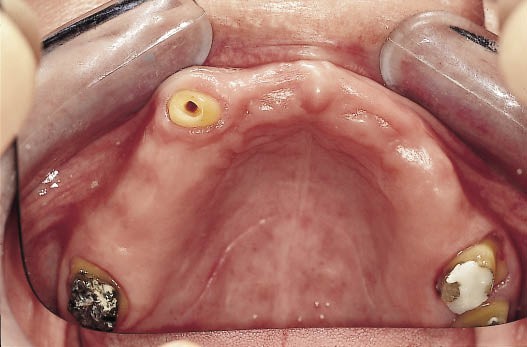
Fig 8-12 Occlusal view of the teeth prepared for a metal-acrylic bridge to provide the patient with a fixed restoration throughout the treatment time. The treatment of this patient has been described in Chapter 10.
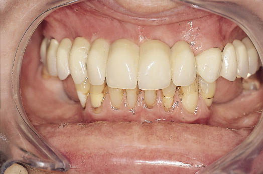
Fig 8-13 Labial view of the metal-acrylic bridge in place. The bridge will provide functional and aesthetic feedback during the course of the treatment, which requires augmentation and implant placement.
Fixed Resin-bonded Bridges
The preferred type of resin-bonded bridge is the Rochette constructed from metal and acrylic.121 The design of the retainer with retention holes allows for predictable removal and re-cementation at the time of surgery (Figs 8-14–8-17). The acrylic resin allows the pontic to be bonded directly to the tooth, when required, for additional stability. Furthermore, alteration, both in terms of reduction and addition, is facilitated. The design of the metalwork should allow modifications of the acrylic resin without interference with the metal (Figs 8-18–8-20). The choice of material should be such that it has sufficient strength in thin sections. The preferred material for bonding the Rochette retainer is a powder- and liquid-based composite (New super C; Amco, Fremont, CA, USA). This bonds directly to the acrylic tooth, any residual composite on the tooth surface and the etched surface of the tooth. Consequently, re-cementation after completion of surgical procedures is greatly facilitated. The clinical evaluation of the Rochette bridge demonstrates its usefulness as a means of temporarily replacing missing teeth during implant treatment.122
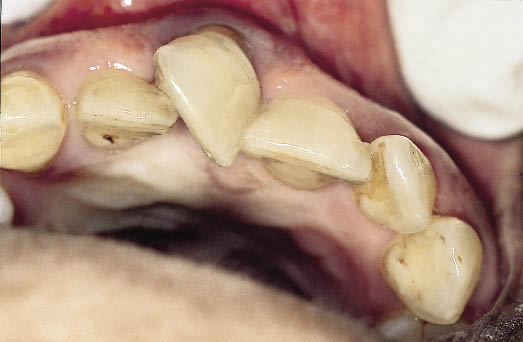
Fig 8-15 Occlusal view of the same patient showing a limited amount of space available for the rotated central incisor between the adjacent teeth.
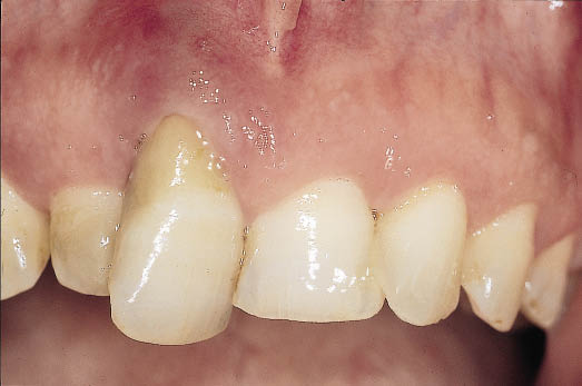
Fig 8-14 Labial view of a periodontally involved central incisor. The extrusion of the tooth as well as the associated bone loss is apparent.
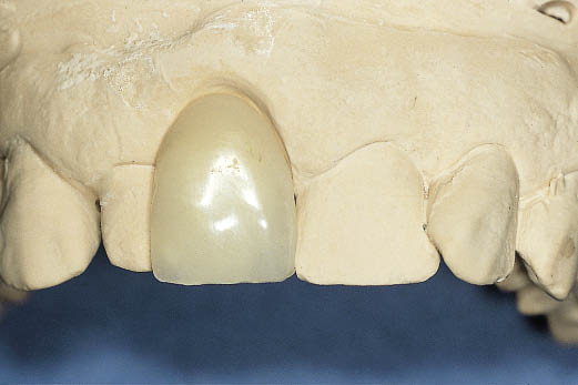
Fig 8-16 A provisional metal-acrylic Rochette bridge provides an excellent opportunity to assess the manner in which the reduced space can be managed. The clinician and patient are able to assess the appearance that can be achieved by overlapping the lateral incisor with a tooth matching the left central incisor in width.
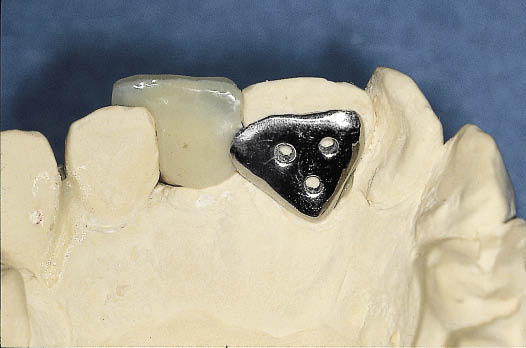
Fig 8-17 Occlusal view of the metal-acrylic Rochette bridge showing the use of a single retainer on the palatal aspect of the central incisor. The design of the Rochette bridge using three holes to provide mechanical retention for the bridge to the tooth greatly facilitates the removal and replacement of the bridge. The single retainer provides very predictable retention during the treatment period. The manner in which the reduced amount of space available is used for the broader incisor is also apparent.
Fig 8-18 Labial view of metal-acrylic Rochette bridge showing the increased cervical length of tooth caused by the loss of bone in the left central incisor region. This Rochette pontic is diagnostic of the need to increase the amount of bone by means of a bone graft.
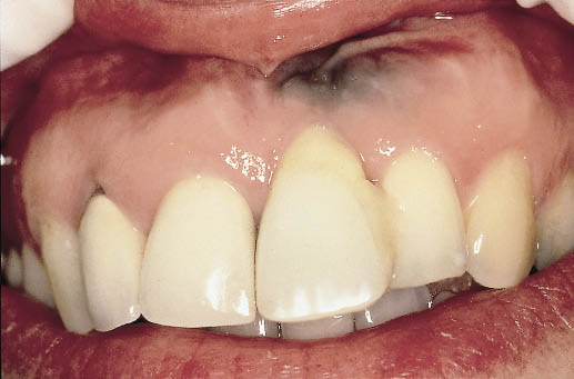
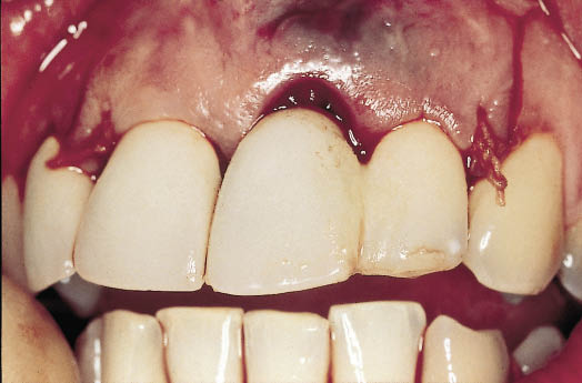
Fig 8-19 The Rochette bridge fitted following the bone grafting procedure to reconstruct the deficiency. The Rochette pontic has been reduced to permit seating and is indicative of adequate reconstruction. The amalgam tattoo has been displaced coronally as the soft tissue is advanced to cover the graft.
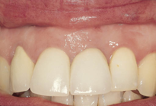
Fig 8-20 The completed definitive restoration supported by an implant following soft tissue corrective surgery. (Restorative phase completed by Dr Russ Ladwa, London, UK.)
The design of the Rochette will depend on the clinical situation as follows.
- • Tooth surface. The ideal surface for bonding is enamel, which can be etched for adhesion of the composite cement. Porcelain surfaces need to be blasted, etched with hydrofluoric acid and treated with a silane-coupling agent before bonding with composite. Dentine-bonding agents do not offer the same bond strength as those bonding to enamel. Metal surfaces are unsuitable for bonding within the mouth if they are not silicoated (e.g. tribochemical coating with CoJet, 3M-ESPE; St Paul, MN, USA) and prepared with a silane-coupling agent.123–125 Enamel remains the most predictable surface, producing good bond strength. When an adequate surface area for bonding is available, single retainers offer the most predictable results for single anterior teeth (Figs 8-17 and 8-21).
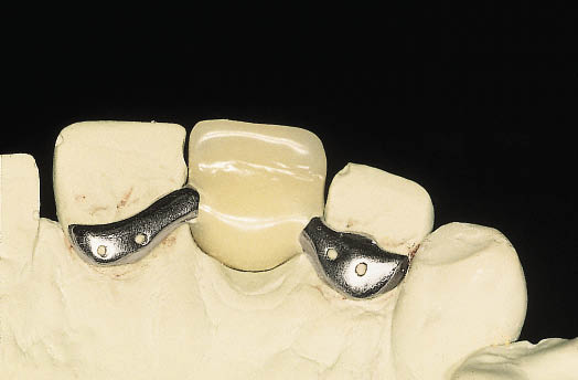
Fig 8-21 The use of two wings may become necessary because of the amount of space available in patients where there is substantial contact with the teeth in the opposing jaw. Using bilateral retainers compensates for the reduction in the surface area for retention.
- • Occlusal clearance. Sufficient space is necessary for a stable retainer (minimum thickness of 0.5 mm). In the absence of adequate space, the retainer needs to be located at a distance from the pontic area (Figs 8-22–8-24). Alternatively, the Dahl principle can be applied, which involves incorporating a platform that will come into contact with the opposing teeth prematurely, thus adjusting the occlusal levels; alternatively the opposing dentition can be adjusted, but this may be met with resistance from the patient (Figs 8-25–8-30).126
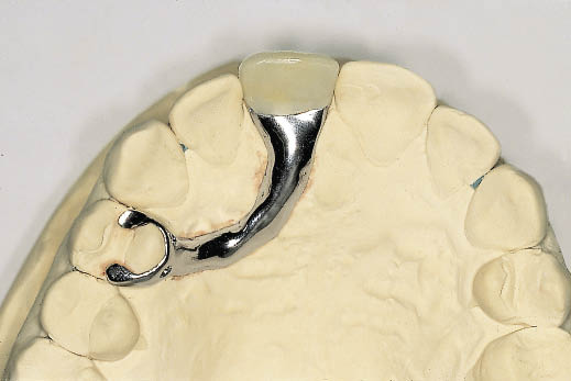
Fig 8-22 Occlusal view of a spring cantilever metal-acrylic Rochette bridge that gains support and retention from a premolar tooth. The spring cantilever bridge becomes indicated in situations where the adjacent teeth have a surface that is difficult to bond to or when inadequate occlusal clearance is available. The use of occlusal rests facilitates seating. The extension of the retentive wing onto the buccal aspect would provide greater security but interferes with aesthetics.
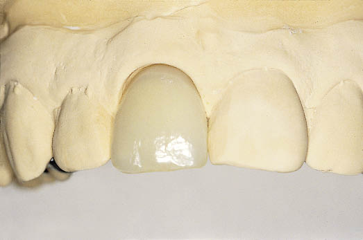
Fig 8-23 Labial view of the spring cantilever Rochette bridge demonstrating its use as a diagnostic tool.
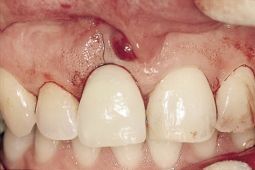
Fig 8-24 Clinical view of the Rochette bridge described above on cementation immediately after the extraction of the maxillary right central incisor.
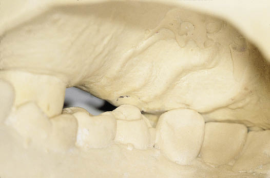
Fig 8-25 Palatal view of diagnostic study casts in occlusion showing inadequate occlusal clearance. The mandibular premolar can be seen in contact with the upper mucosa.
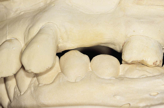
Fig 8-26 Labial view of the study casts showing the bucco-lingual relationship of the teeth and the opposing alveolar ridge.
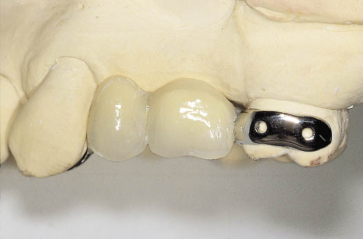
Fig 8-27 Labial view of metal-acrylic resin Rochette bridge, which utilises a buccal wing on the second molar for support and retention.
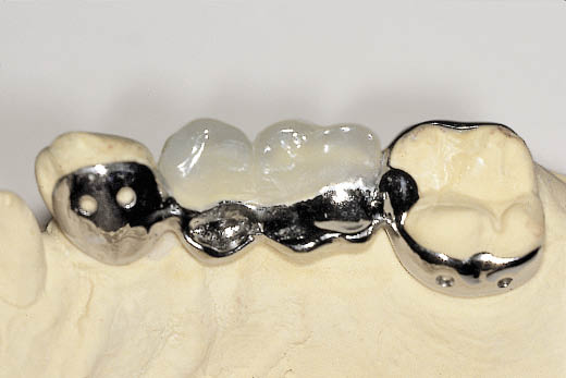
Fig 8-28 Occlusal view of Rochette bridge showing a palatal wing on the canine and the second molar. In addition the occlusal rest on the molar is visible. The occlusal surfaces of the premolar and molar teeth have been designed out of metal to intercuspate with the overerupted mandibular premolars, utilising the Dahl principle for the creation of interdental space.
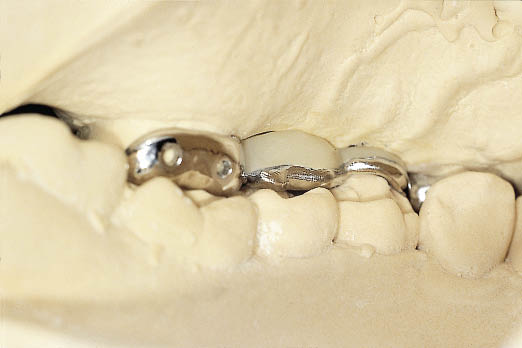
Fig 8-29 Palatal view of articulated study casts with Rochette bridge in situ.
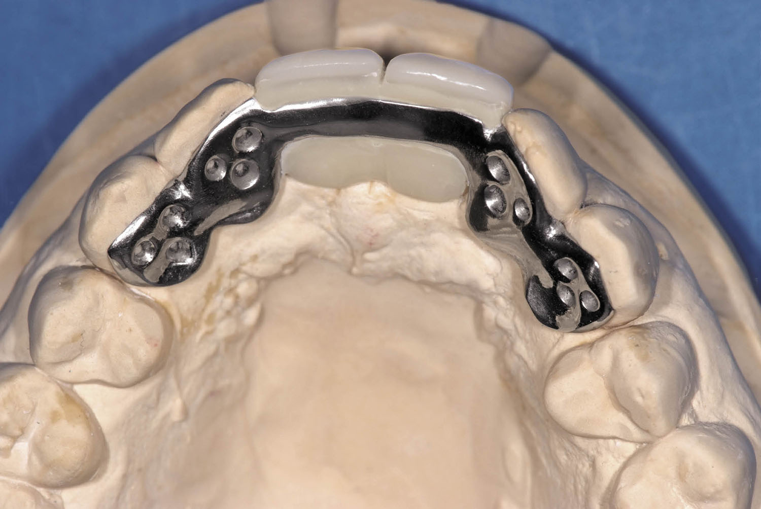
Fig 8-30 Occlusal view of a Dahl appliance/Rochette bridge, designed to intrude the mandibular incisors to create space for bone graft and implants in a patient with a traumatic bite directly into the palatal soft tissues. The use of retainers on the lateral incisors and canines was designed to provide stability to the maxillary provisional restoration.
- • Location of retainer and pontic. When posterior teeth are being replaced, retention for the Rochette bridge can be gained from the buccal and palatal surfaces of the molar teeth. The ability to provide retention and occusal rests makes posterior Rochette bridges very stable, with a minimum risk of debonding.
- • Distance between pontic and retainer. In the event that no suitable teeth are available to bond to, a retainer at a site distant to the pontic may be selected and connected by a spring cantilever.
Rochette bridges can be constructed to extend over long spans replacing many teeth with several retainers and offer the advantage of preserving tooth tissue, particularly where the abutment teeth are sound (Figs 8-31–8-44). However, only limited changes in the occlusal scheme are practicable with this modality.
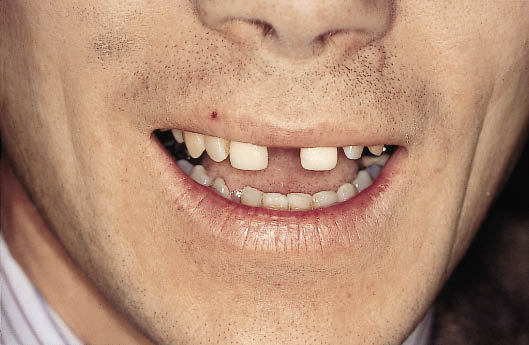
Fig 8-31 Preoperative photograph of a patient with a large central diastema posing a difficult restorative problem which requires accurate diagnostic resolution prior to embarking on surgical procedures to replace the two central incisors with implants.
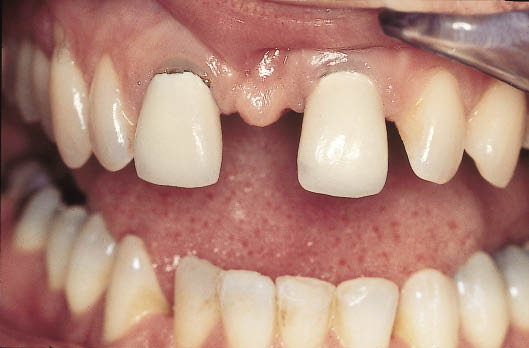
Fig 8-32 Intraoral labial view of failing crowns providing an idea of the dimensions of the diastema that need to be addressed.
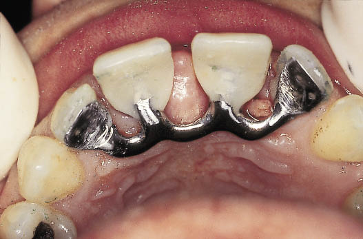
Fig 8-33 Palatal view of spring cantilever metal-acrylic Rochette bridge retained by the two lateral incisors.
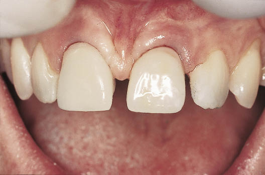
Fig 8-34 Labial view of the metal-acrylic Rochette bridge in situ. The bridge will provide both the clinician and the patient with an opportunity to assess the appearance before proceeding with the surgical treatment. The position of the bone graft and implants is determined by the tooth position, which must first be approved.
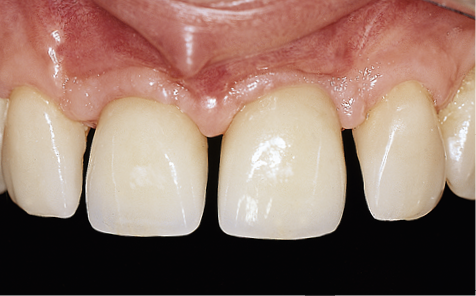
Fig 8-35 Labial view of the definitive restorations consisting of two implant-supported crowns replacing the central incisors and porcelain veneers on the lateral incisors reducing diastemas between the central and lateral incisors.
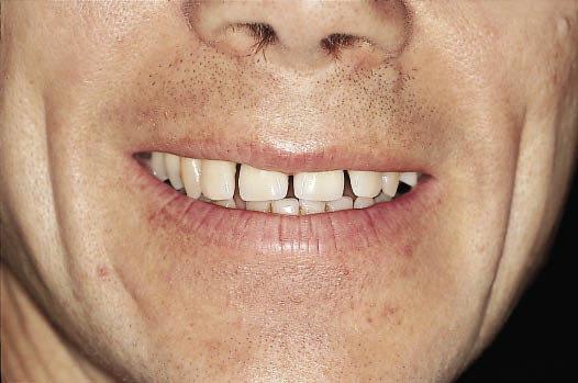
Fig 8-36 Frontal view of the patient smiling with the definitive restorations.
Fig 8-37 Anterior view of patient with advanced periodontal disease exhibiting a large diastema caused by the drifting of the anterior teeth. (Same patient as in Fig 14-42.)
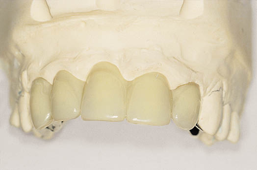
Fig 8-38 Labial view of the metal-acrylic Rochette bridge designed to replace five anterior teeth. Note that the diastema has been eliminated and the size and position of the replacement teeth needs to be verified functionally and aesthetically.
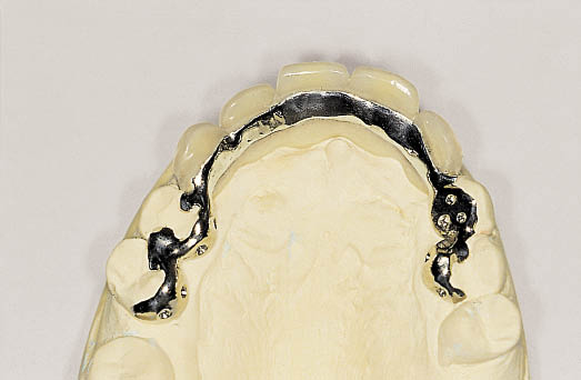
Fig 8-39 Occlusal view of the Rochette bridge showing the wings, which will provide retention for the bridge.
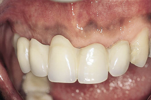
Fig 8-40 Rochette bridge in situ showing the appearance that has been achieved.
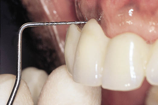
Fig 8-41 Lateral view of the Rochette bridge relating the tooth position, which has been selected for functional and aesthetic outcome, to the healed residual alveolar ridge.
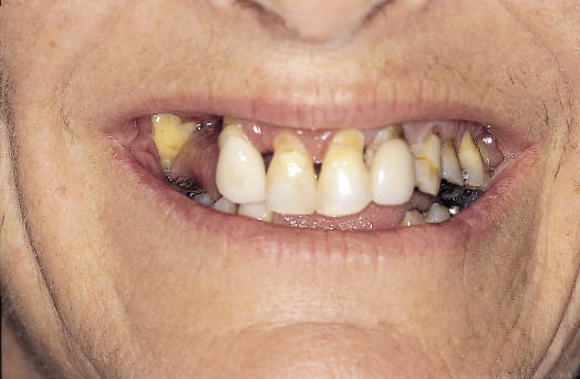
Fig 8-42 Preoperative anterior view of a patient with failing dentition.
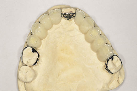
Fig 8-43 Occlusal view of the laboratory cast with large-span metal-acrylic Rochette bridge.
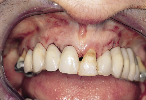
Fig 8-44 Labial view of the same Rochette bridge cemented into place immediately on extraction of the failing teeth.
Hybrid Bridges
Rochette retainers and full-preparation retainers can be combined wherever appropriate, resulting in a hybrid bridge. Such a structure is typically used when there is a large space bounded at one end by a tooth that needs crowning and at the other by a tooth that would be inappropriate to crown (Figs 8-45–8-50).
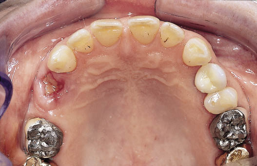
Fig 8-45 Occlusal view of patient requiring restoration of the maxillary premolars with implants. The molar is restored with a crown that requires replacement, the canine is unrestored. (Same patient as Fig 10-18.)
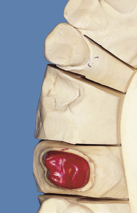
Fig 8-46 Occlusal view of the working cast with the prepared die of the first molar.
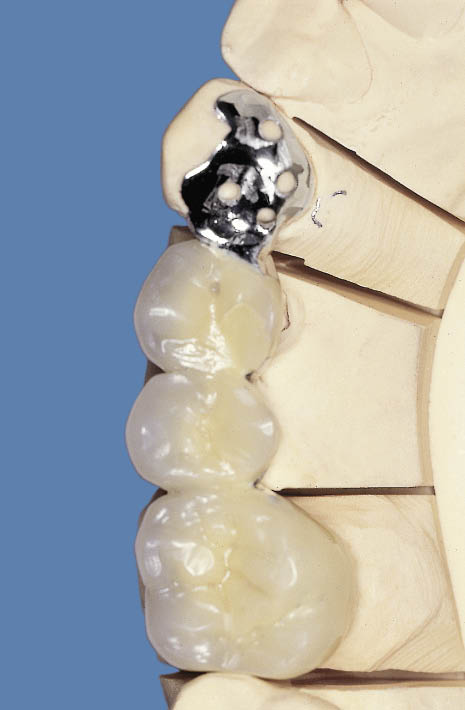
Fig 8-47 The completed metal-acrylic bridge with full coverage retainer on the first molar and a metal Rochette wing on the canine.
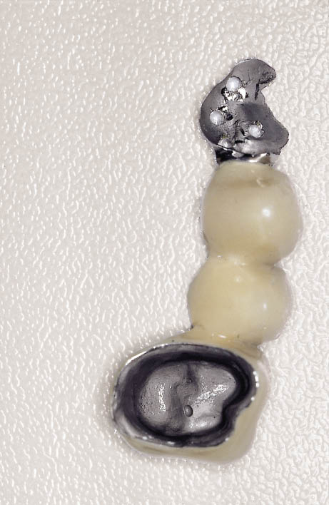
Fig 8-48 Fit surface of the hybrid metal-acrylic Rochette bridge.
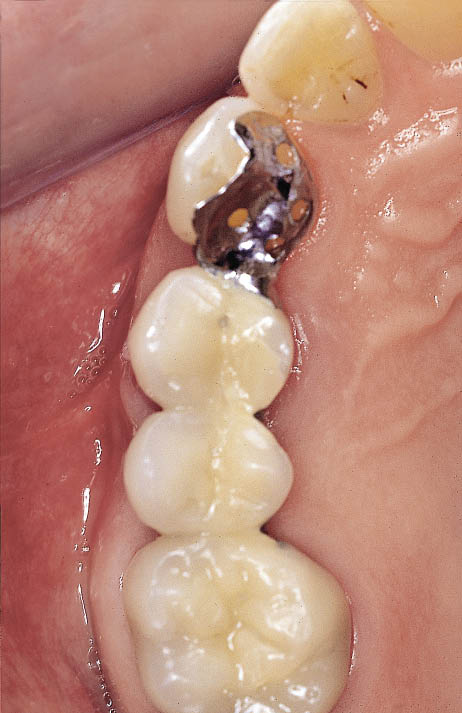
Fig 8-49 Occlusal view of the fitted metal-acrylic hybrid Rochette bridge.
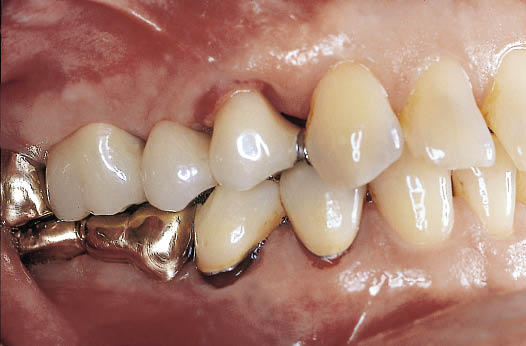
Fig 8-50 Labial view of the same fixed partial denture as shown in Fig 8-49.
Considerations Specific To Immediate Loading
When deciding whether immediate loading is possible, the main criteria to be considered are as follows (see also Chapter 7):
- • Adequate bone density to allow primary stability to be achieved.
- • There should be adequate bone width as it may not be appropriate for an implant to be loaded immediately following the manipulation of the labial plate, which may well, in turn, result in compromised primary stability.
- • The absence of any minor bone deficiencies that may require the use of a membrane for guided bone regeneration.
- • Aesthetics are of prime importance for consideration in the anterior maxillary region. The protocol for delayed loading offers more opportunities to position the implant precisely and to re-contour the soft tissues during implant placement. It also provides a second opportunity to create the required emergence profile by positioning the incision for implant exposure based on the contours established on completion of integration. Furthermore, impressions at first-stage surgery can be taken. This provides the opportunity to have the abutment and transitional restoration available at the time of implant exposure to create the desired soft tissue profile.
If immediate loading is planned, its execution will be dependent on the achievement of adequate primary stability at implant placement, as introduced in the chapter on immediate placement (Chapter 7).
Therefore, additional component parts and laboratory work must be planned (see below under immediate loading). The steps prior to delayed placement of an implant in a healed site are summarised in Table 8-1.
Table 8-1 Assessment checklist of a future implant site for delayed placement
|
Degree of healing |
|
|
Pathology |
|
|
Amount of bone |
|
|
• height |
|
|
• width |
|
|
• length of ridge |
|
|
Soft tissue check |
|
|
Gingival margin |
|
|
Papillae |
|
|
Bone density |
|
|
Diagnostic preview |
|
|
Provisional restoration |
|
Implant Placement
Access to the bony ridge depends on the preoperative criteria, which would determine whether immediate or delayed loading is planned. The clinical stages for delayed placement of implants with intended immediate loading are summarised in Flowchart 8-3 (see pp. 120–121). Where delayed loading is planned, two-stage surgery is intended using a remote incision for stage one and a suitable incision for exposure of the implant at the second stage, as outlined in Chapter 9.
Incision for Delayed Loading
Access to the bony ridge should be made using remote incisions to reduce the risk of early implant exposure. Remote palatal incisions are used in the maxilla (Figs 8-51 and 8-52) and remote buccal incisions in the mandible. Crestal incisions may also be used, particularly in the mandible. Closure of a crestal incision should be carried out using a suturing technique that ensures tight wound closure.
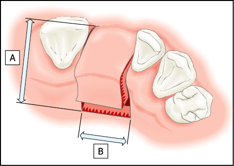
Fig 8-51 Diagram of a palatal incision for delayed loading. Little or no exposure of the labial cortical plate is necessary. The incision consists of two separate components: (A) incisions perpendicular to the ridge extending 10 mm into the palate on either side of the gap; (B) a bevelled component, which is executed parallel to the ridge and joins the two incisions made perpendicular to the ridge. This is normally carried out by means of a Blake’s knife. This produces a buccally based flap, the incision remaining distant from the site where the implant and any augmentation material might be positioned.
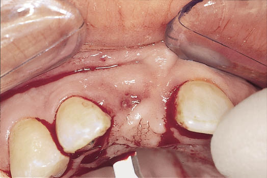
Fig 8-52 Occlusal view of the ridge showing the palatal component of the incision for the remote buccally based flap made using a Blake’s knife. The flap design is depicted in Fig 8-51.
Incision for Immediate Loading or for Transgingival Healing
A crestal incision is necessary to be able to attach the abutment or sulcus former following implant placement. The precise location of the incision should be designed to create the soft tissue contours required. In the maxilla, the incision is made towards the palatal aspect of the crest, which provides a surplus of tissue on the labial aspect and thus the option of manipulating it to create the gingival margin and papillae (Figs 8-53 and 8-54). Alternatively, a broad ‘H’-shaped incision may be used where the procedure can be carried out with minimum exposure of the bony ridge. Attached keratinised tissues are sparse in the mandible and it therefore becomes necessary to bisect the available tissue. Certainly the incision should not be made towards the lingual aspect because of the very friable natu/>
Stay updated, free dental videos. Join our Telegram channel
VIDEdental - Online dental courses


