7
Molar Distalisation
Whilst buccal mini-implants are relatively easy to insert, their interproximal position, in close proximity to the buccal roots of adjacent molar teeth, limits the amount of nearby tooth movement which may occur. Consequently buccal anchorage approaches provide only limited scope for molar distalisation and typically require a two phase distalisation process: initially for molar movement and secondly for retraction of the premolar and anterior teeth. Furthermore, the mini-implants need to be re-located between these two phases, risking anchorage loss during this switch-over process. Fortunately, the availability of the hard palate for bone anchorage substantially increases the options for upper molar distalisation. Therefore, the choice of mini-implant site depends on the planned amount of maxillary molar movement and on whether the mid-palate area is easily accessible (which may not be the case in high arched palate cases). For example, up to half a unit of distalisation may readily be achieved using direct traction from mini-implants sited in the palatal alveolus. A greater range of distalisation and probably better bodily control over the molars’ movements are both achieved through indirect palatal anchorage of a customised distaliser appliance. Importantly, this differs from the use of ’non-compliance’ distalisers since the incorporation of mini-implants avoids anchorage loss during both the distalisation and subsequent retraction phases, in the form of mesial movement/proclination of the anterior teeth and then molar anchorage loss.1,2
The options for distalisation of mandibular molars are limited to using anchorage sites in either the posterior alveolus (e.g. just mesial to the first molar) or the retromolar area. However, the latter site may be complicated by the presence of the third molar, difficult physical access and a lack of attached gingiva (a shallow buccal sulcus).
Clinical objectives
- Prevention of mesial movement of the premolars and anterior teeth during molar distalisation.
- Prevention of molar mesial movement (anchorage loss) during subsequent retraction of the anterior teeth.
Treatment options
- Buccal alveolar mini-implant anchorage (direct or indirect) in either arch.
- Palatal alveolar mini-implant anchorage.
- Mid-palate mini-implant distaliser.
- Premolar extractions (where none have previously been undertaken), avoiding the need for molar distalisation.
- Headgear, possibly with an upper removable appliance (e.g. a ‘Nudger’), for upper molar distalisation.
- Correction of the skeletal base (negating distalisation requirements) by orthognathic surgical or orthopaedic appliance treatments.
Key treatment planning considerations
- The molar, canine and skeletal base relationships.
- Eruptive status of the second molars: there is less resistance to molar distalisation before eruption of the second molars, but also a greater tendency to molar tipping (rather than bodily movement).3
- Presence/absence of third molars: consider their removal (before orthodontics) if they are likely to interfere with distalisation.
- Absence of posterior teeth (due to previous extractions or hypodontia).
- Depth and shape of the palatal vault, i.e. a high arched palate makes access difficult for mid-palate insertion of both mini-implants and a distaliser.
- Distalisation distance required and whether this differs for each side of the arch.
- Avoid maxillary buccal alveolar insertions since there is very limited interproximal space for distal movement of adjacent roots past the mini-implant. Hence, this approach requires re-siting of the mini-implants after molar distalisation and before the second phase retraction of the premolar teeth.
- Sufficient interproximal space is available between the maxillary palatal roots for both insertion and up to half a unit distalisation of teeth (before the mini-implant is approximated by roots mesial to it).
- Mid-palate anchored distalisers require more initial clinical, and especially laboratory, time due to their fabrication and fitting requirements. However, once in situ they are simple to reactivate and provide the best range for distalisation. They may also provide optimum bodily molar movements, followed by simple retraction of the anterior teeth.4,5,6,7,8
Biomechanical principles
- Forces applied at the coronal level will tend to distally tip molars during distalisation, then risk anchorage loss as the molars upright during retraction of the anterior teeth.1
- Distalising forces directed at the furcation level will produce molar bodily movement.1
- First molars tend to distally tip when the second molars are unerupted.3
- There is a tendency to molar crossbites as the molars distalise. This is exacerbated when a rigid transpalatal arch (TPA) is used, or when insufficient compensatory transverse coordination is incorporated in the fixed appliance archwires or a distaliser appliance’s wire frame.
Mid-treatment problems and solutions
- If there are signs of molar tipping then over-correct their distalisation, in anticipation of molar relapse during retraction of the anterior teeth.
- It may be necessary to accept buccal crossbites, especially if a rigid TPA is used, until after the anchorage requirements have been met. However, if alveolar mini-implants are being used for direct traction then arch coordination can be attempted, e.g. by expansion of the maxillary archwire.
- Patients should alert the orthodontist as soon as they become aware of the breakage of any components to prevent anchorage loss or unfavourable tooth movements.
Mandibular arch distalisation
This involves mini-implant insertion in either posterior interproximal sites or the retromolar area.
Pre-insertion
Mini-implant selection
Insertion
Post-insertion
Figure 7.1 (a) Pre-treatment view showing the Class II malocclusion with absent lower right second molar, moderate crowding and lingual displacement of the lower right second premolar. (b–d) A mini-implant in the lower second molar site providing indirect anchorage using a ligature wire to the first premolar then canine brackets, whilst a compressed coil spring distalises the first molar. (e, f) Alignment of the second premolar after molar distalisation had created ample space.
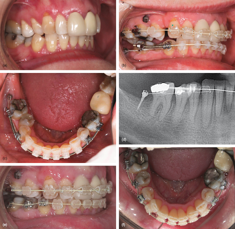
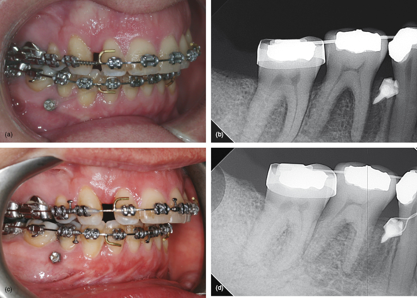
Figure 7.2 (a, b) Pre-surgical decompensation in this Class II case required incisor retraction, but the lower first premolars were already absent. These views show a mini-implant sited close to the right first molar root to provide sufficient range of arch distalisation before premolar–implant proximity occurs. Elastomeric traction applied to an archwire hook provides en masse retraction and a modest molar intrusive side-effect. (c, d) Traction completed prior to a mandibular osteotomy.
- An adult with a Class II division 2 malocclusion with absent lower right second molar and lingual displacement of the lower right second premolar tooth (Fig. 7.1a).
- The lower arch, except the right second premolar, was aligned ready for insertion of a 0.019 × 0.025 steel archwire (Fig. 7.1b).
- A 1.5 mm diameter, 9 mm body length, long neck Infinitas mini-implant was inserted on the buccal aspect of the alveolar ridge and distal to the lower right first molar. It was used to indirectly anchor the right premolar then canine teeth (Figs 7.1b–d).
- Anchorage was discontinued once molar distalisation had created space for alignment of the second premolar (Figs 7.1e, f).
- An adult with a Class II division 2 malocclusion with absent first premolars, recent removal of the lower right third molar, and requiring incisor decompensation for a mandibular advancement osteotomy.
- Treatment commenced with arch alignment to accommodate a 0.019 × 0.025 stainless steel archwire, but with the lower first molars mesially tipped to increase the interproximal space on their mesial aspects (Fig. 7.2a).
- />
Stay updated, free dental videos. Join our Telegram channel
VIDEdental - Online dental courses


