6
Incisor Retraction
When most orthodontists think of anchorage it is probably a scenario involving the use of an intra-oral appliance or headgear to stabilise the maxillary molars during retraction of the anterior teeth. Unsurprisingly, this was one of the first identified applications for mini-implants, with traction applied directly from the mini-implant (typically inserted buccally between first molar and second premolar roots), sparing molar involvement and hence anchorage loss. Both clinical experience and published studies have shown that mini-implant usage enables orthodontic treatment goals to be more fully realised, in terms of full incisor retraction without anchorage loss, than the traditional gold standard of headgear anchorage.1,2,3,4,5,6,7,8 Indeed, anchorage gain has been observed whereby the maxillary molars have been distalised by the continuation of traction after closure of the premolar spaces. In addition, intrusive side-effects on the molars may assist with Class II correction, due to favourable mandibular counter-clockwise autorotation (measured as a reduction in the mandibular plane angle and an increase in the SNB angle). Therefore, it appears that mini-implant anchorage produces both substantial anchorage effects and also (somewhat unexpectedly) fixed appliance biomechanical side-effects which are different and more multi-dimensional than those effects observed with conventional anchorage. For example, if traction is applied directly to a canine bracket, with a steep vertical direction (vector) and with a flexible archwire in situ, then pronounced distal tipping of the canine causes a ‘rollercoaster′ buckling of the buccal segment (Fig. 6.1). Similarly, if a steep vector of traction is applied to the labial segment, with a rigid archwire in situ, it may cause the side-effect of clockwise rotation of the entire maxillary arch and consequently molar intrusion (Fig. 6.2). Therefore, in average and deep overbite cases, mini-implant traction should be applied parallel to the occlusal plane (with a horizontal vector) by crimping a powerarm (an elongated vertical hook) on to the anterior part of the archwire (Fig. 6.3). This minimises the rotational effect on the whole arch and also produces more favourable bodily retraction of the anterior teeth (than can be achieved with conventional biomechanics) because the traction is applied closer to their centres of rotation.3,8,9,10 Finally, unlike conventional anchorage options, mini-implants also offer both direct and maximum anchorage reinforcement in the mandibular arch.
Figure 6.1 Alveolar necking in the right maxillary first premolar extraction site, resulted in very difficult distalisation of the adjacent canine in this adult patient. Consequently, elastomeric traction applied from the mini-implant to the upper canine bracket caused (a) distal tipping of the canine and a rollercoaster bowing of this 0.018 NiTi archwire, then (b) molar intrusion when traction continued on a rigid archwire.
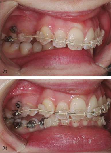
Figure 6.2 (a) This adult patient had extraction of the upper right second premolar for canine and incisor retraction. (b) The steep vector of elastomeric traction applied from the mini-implant to the upper canine bracket, although with rigid archwires in place, caused intrusion of the adjacent first molar, premolar and canine teeth. However, this was partially favourable in this case because of the reduced overbite, although the second molar should have been included for the full benefit of this vertical side-effect.
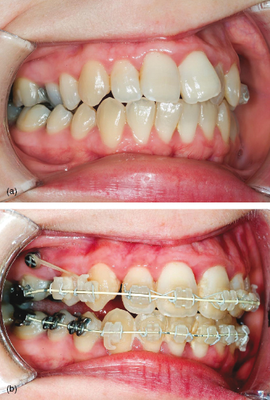
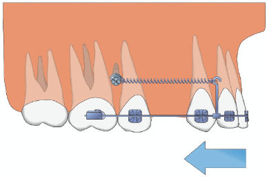
Figure 6.3 Diagram of a horizontal vector of traction from the posterior mini-implant to a powerarm fixed on the anterior archwire, causing bodily retraction of the anterior teeth (without molar intrusion).
Clinical objective
- Prevention of mesial movement of the upper or lower molars during retraction of the anterior teeth for overjet reduction and/or centreline correction.
Treatment options
- Direct bone anchorage by applying traction from a mini-implant inserted in the posterior alveolus, in either jaw.
- Indirect alveolar bone anchorage using a mini-implant to stabilise the posterior teeth (the dental anchorage unit) e.g. by a ligature from the mini-implant to an anchor tooth (Fig. 6.4).
- Indirect bone anchorage (maxillary arch only) using mid-palate mini-implants.
- Conventional anchorage, e.g. headgear, transpalatal arch, lingual arch.
- Intermaxillary elastics for indirect anchorage.
- Correction of the skeletal base (negating the anchorage requirements) using orthognathic surgery or orthopaedic (functional) appliance treatments.
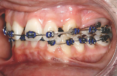
Figure 6.4 Indirect anchorage using a stainless steel ligature from the posterior mini-implant to the canine bracket, enabling active traction from this canine to retract the adjacent incisors (in this adolescent patient with an absent upper right central incisor).
Key treatment planning considerations
- The anchorage requirements, as indicated by the overjet, incisor inclination, distance that the canines need to be retracted into Class I (allowing for any canine movements in the opposing arch), buccal segment relationships and extraction pattern.
- Overbite: this affects the ideal vertical level of the mini-implant and the vector of traction, i.e. the more apical the position of the mini-implant head then the more potential for molar intrusion in a reduced overbite case.
- Centrelines: is there a need for asymmetrical incisor retraction?
- Morphological or prognostic differences between the posterior teeth which may influence the extraction pattern, e.g. loss of a restored or macrodont/microdont second premolar may be indicated rather than a virgin first premolar even if this increases the anchorage demands.
- Is there sufficient interproximal space between the first molar and second premolar roots, or is preliminary root divergence required?
- The amount of incisor crowding: is there a need for preliminary canine retraction to enable incisor alignment (prior to overjet reduction)?
- If there is insufficient primary stability in buccal alveolar sites (in adolescent patients) then consider using the mid-palate as a source of indirect anchorage. For example, two short length and wide diameter mini-implants (e.g. Infinitas 6 mm length, 1.5 or 2 mm diameter) may be inserted in para-sagittal positions and used to anchor the Nance button of a transpalatal arch (TPA). This stabilises the upper molar anchor teeth, but there is a risk of anchorage loss if the TPA bends due to insufficient rigidity. There are also clinical time and additional (laboratory) cost implications due to the need for fabrication of a customised TPA or Nance arch, plus traction can only be applied at the coronal level from the molar hooks.
Biomechanical principles
- Increased overbite case: consider adjunctive intrusion of the anterior teeth using additional anterior mini-implants.
- Reduced overbite case: bond the second molars (if fully erupted) during the alignment phase so that they can be actively intruded during space closure, by virtue of the rotational effect of oblique traction on the arch. The molars may be further intruded by direct vertical traction after the space closure phase.
- Determine the ideal traction vector prior to mini-implant insertion. For example, if there is sufficient height of attached gingiva then the mini-implant may be vertically sited at a relatively apical level, but with the potential effect of producing an oblique (steep) vector of traction and consequently molar intrusion (Fig. 6.5a). Conversely, if there is only a narrow band of attached gingiva then the mini-implant is limited to a coronal insertion level, resulting in closer proximity to the archwire plane and a relatively horizontal line of traction (Fig. 6.5b).
- The force vector may also be altered by application of the traction to a powerarm: an elongated hook attached to the archwire or a bracket (Fig. 6.3). This has three effects/uses:
- Elimination of the vertical component (vector) of the traction since the powerarm enables traction to be attached at the same vertical level as the mini-implant head. This minimises the risk of inadvertent molar intrusion, due to clockwise arch rotation.
- The powerarm facilitates more bodily retraction of the incisors since the traction is applied closer to the centre of rotation of the anterior teeth.
- A single tooth powerarm is also very useful for controlled canine retraction in cases requiring space for relief of incisor crowding (Fig. 6.6). This greatly assists bodily canine distalisation and reduces the risk of the rollercoaster phenomenon (Fig. 6.1)/>
Stay updated, free dental videos. Join our Telegram channel
VIDEdental - Online dental courses


