Chapter 7
Immediate Placement and Computer-guided Surgery
Introduction
The concept of removing a tooth that is failing and replacing it with an implant that is brought into function immediately has tremendous attraction. Delayed loading of immediately placed implants is a very well-established technique that has a high success rate.4,5,59–61 The most obvious benefits of this technique to the patient are the reduction in treatment time and considerable convenience in comparison with conventional implant treatment. Another reported benefit of immediate placement is the preservation of bone.62
Immediate loading of implants placed in healed sites is also well established and depends on absence of micro-movement (primary stability) during the healing phase.63–65 It has recently been shown that bone healing around immediately loaded implants results in greater bone density and more mature bone.66–70 The procedure is minimally invasive, allowing the tooth socket to be used for the implant. It is a predictable technique as long as the assessment is carried out accurately. In assessing the benefits and risks of such a procedure, the clinician should bear in mind the remedial steps that would be required to rectify the situation in the event of any complications. Flowchart 7-1 describes the factors that need to be considered in assessing a failing tooth. This will enable the clinician to make a decision and provide a rationale for planning treatment.
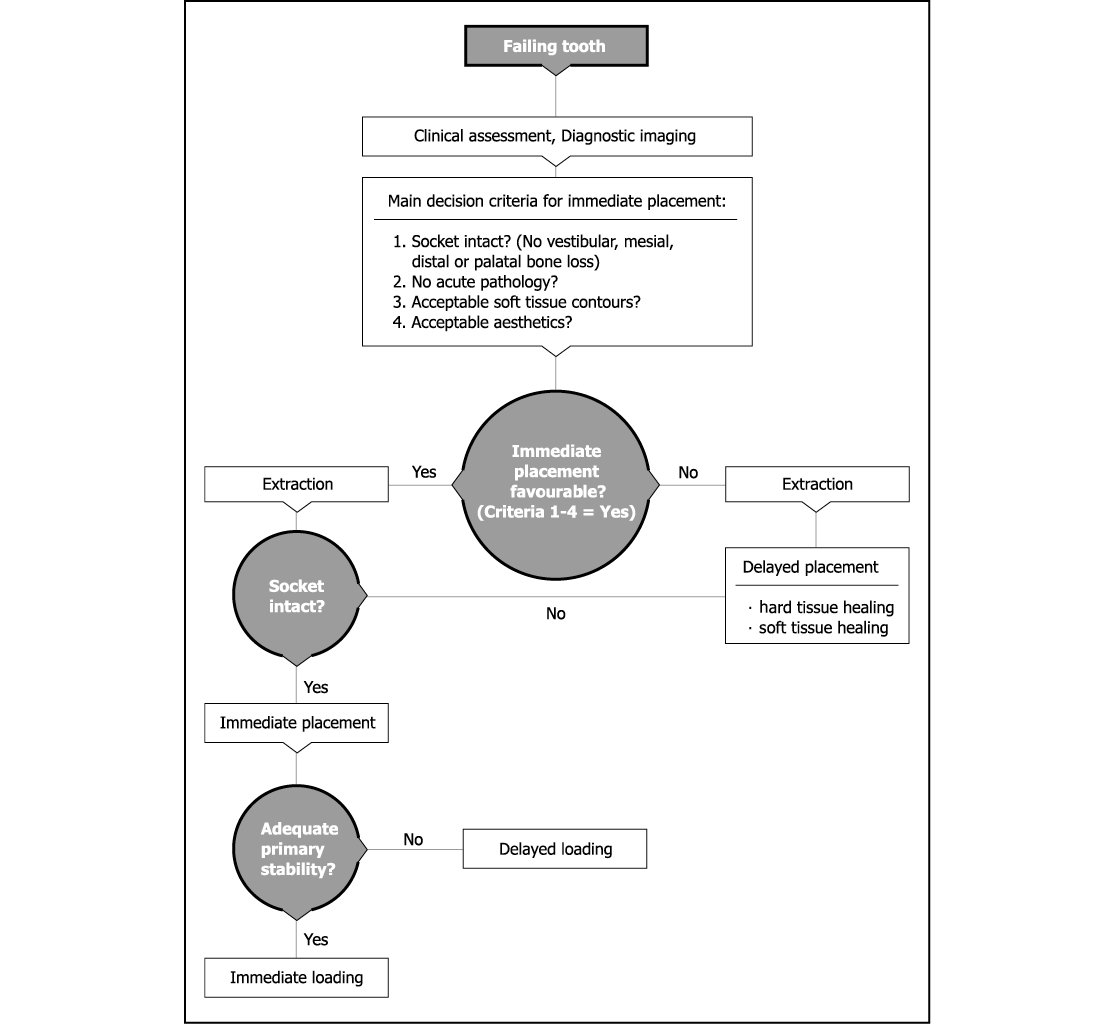
Flowchart 7-1 Assessment for immediate or delayed placement.
Assessment
Clinical Assessment
Absence of Pathology
There should be no acute pathology present in either the periodontal tissues or in the periapical region (Figs 7-1 and 7-2). There should be no sign of symptoms, although it may be acceptable to proceed prudently where chronic well-contained lesions are present.71–76 Vertical root fractures of teeth that have been restored by means of post-crowns should be assessed carefully to ensure that the labial plate of bone has not been compromised (Figs 7-3–7-6).
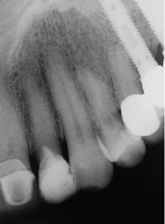
Fig 7-1 Periapical radiograph of lateral incisor with obliterated root canal and almost complete destruction of the coronal portion. No pathology is evident and tooth replacement is for restorative reasons.
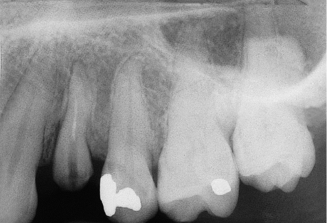
Fig 7-2 Radiograph of first premolar with dislodged post-crown and clinical signs of a fine vertical fracture with no signs of acute pathology. An ideal candidate for immediate replacement with an implant.
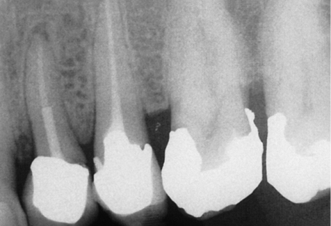
Fig 7-3 Radiograph of first premolar restored with a post-retained crown and a vertical root fracture with a well-contained periapical lesion, ideal for immediate replacement with an implant.
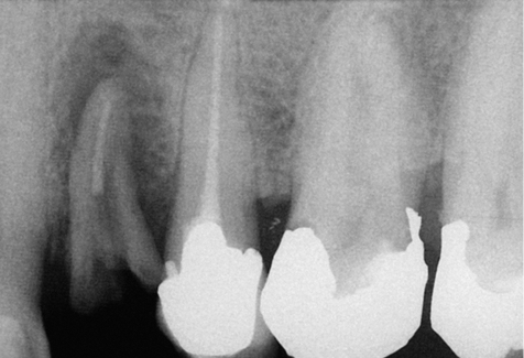
Fig 7-4 Periapical radiograph of the tooth shown in Fig 7-3 3 months later. A delay in treatment has led to the propagation of the fractured root and extensive bone loss resulting from the inflammatory process. Active lesions such as these are not predictable to treat with immediate implants.
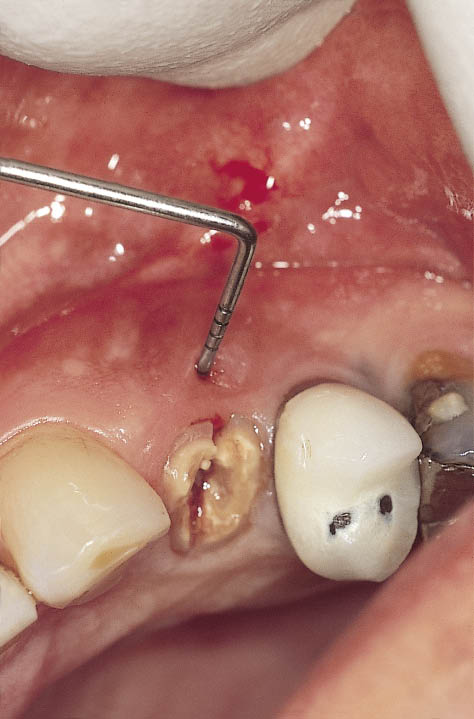
Fig 7-5 Clinical view of the same tooth (Fig 7-4) with labial fistula indicating labial bone loss.
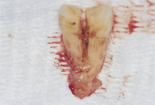
Fig 7-6 The extracted fractured root of the premolar (as shown in Fig 7-5) with associated periapical lesion. This has resulted in the destruction of the entire labial plate as well as considerable periapical bone loss.
Soft-Tissue Health and Aesthetic Contours
The contours of the soft tissues around the tooth to be extracted should be such that they will appear acceptable around the intended restoration. It should be borne in mind that augmentation of the hard and soft tissues in such situations is complex, reducing the predictability and defeating the purpose of a procedure designed to simplify treatment (Fig 7-7). It should also be borne in mind that the soft tissues will remain stable as long as the hard tissues are present to support them.
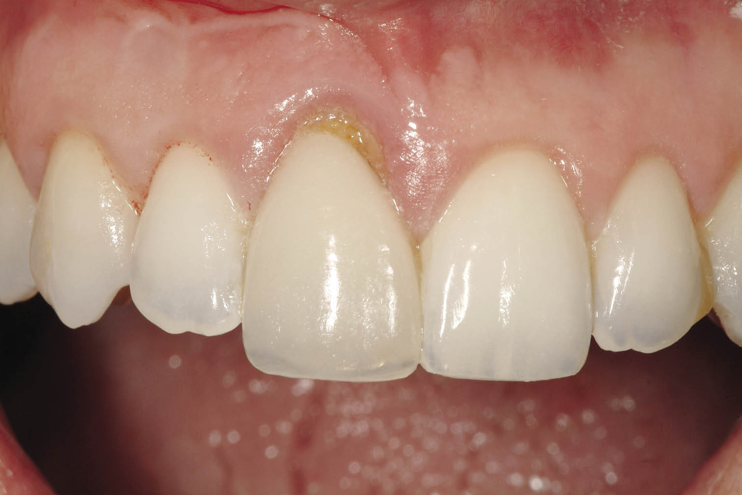
Fig 7-7 Tooth with labial gingival recession in a patient with a high lip line. Satisfactory aesthetics can not be easily achieved without supplementary augmentation procedures.
Socket Integrity
It is of benefit to have a socket that is intact.59 Preoperatively this can be checked by means of periodontal probing (Fig 7-8). Loss of bone around the tooth to be replaced may result in the bone healing to a level that is not predictable. The level of bone that exists in contact with the adjacent teeth is critical because it will be responsible for the maintenance of the papillary height (Figs 7-1–7-3).
Anatomical variations of the teeth make some teeth better candidates for immediate implant placement. Typically the central incisors and canines are more likely to have dehiscent roots (Fig 7-9), whereas the lateral incisors are positioned in a more palatal direction (Fig 7-10).
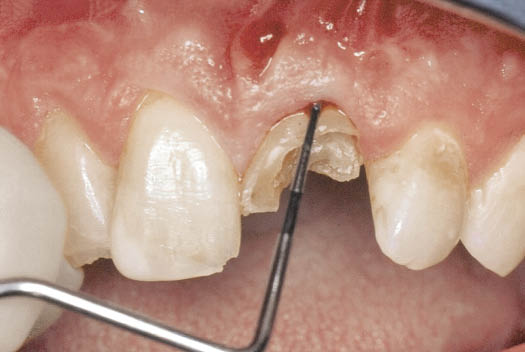
Fig 7-8 Fractured central incisor being assessed for immediate placement with a periodontal probe to assess the likely level of the labial aspect of the bony socket.
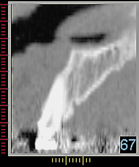
Fig 7-9 Cross-sectional CT image of central incisor showing the inclination of the root, the thin labial cortical plate and the ample bone available on the palatal aspect of the root to achieve primary stability for an implant of adequate dimensions. Implant placement in the direction of the root would clearly lead to a labial fenestration, independent of the shape of the implant used.
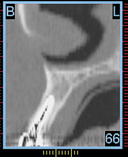
Fig 7-10 Cross-sectional CT image of lateral incisor showing the inclination of the root, which is more favourable for implant placement with a reduced risk of fenestration of the labial plate. Selection of the implant site will need to be on the palatal aspect of the socket apex depending upon the diameter of the implant, which may be selected using an interactive treatment planning program.
Radiographic Assessment
Periapical Radiograph
Periapical radiographs are valuable for disclosing any periapical pathology and establishing interdental bone levels. They may also provide an idea of the available bone height beyond the apex, the mesiodistal dimensions of the roots and the space available between the adjacent roots. They also indicate the mesiodistal orientation of the roots (see Chapter 8 and Figs 7-1–7-3).
Orthopantomograph (OPG)/
Dental Panoramic Tomograph (DPT)
DPT provides an excellent overview of the jaws, confirming the information obtained from the periapical radiographs, in particular the availability of bone beyond the apex.
Computed Tomography
CT provides very useful 3D information regarding the spatial position of the root in relation to the ridge. The orientation of the root in the bucco-lingual plane enables the direction of the projected osteotomy to be determined accurately. The cross-sections provide valuable information regarding the integrity of the lingual and labial plates of bone (Figs 7-9 and 7-10). The unique contribution of the CT scan is to provide a method for measuring bone density (in Hounsfield units). However, care needs to be taken to exclude the high density of the roots. This, therefore, allows the decision regarding immediate loading to be made preoperatively. It also specifies the likelihood of using the series of instruments available for ensuring the primary stability of the implant by altering bone density (Fig 7-11).
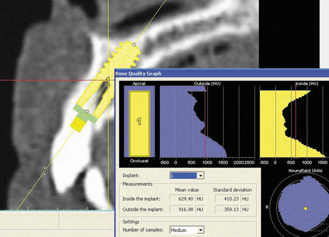
Fig 7-11 Interactive treatment planning showing the bone density in Hounsfield units in the region of the implant site. The high density resulting from the tooth root should be ignored. The density around the apical portion of the implant (<500 HU) indicates that bone condensers may well be needed in order to achieve the primary stability required for immediate loading.
Treatment Sequence
The assessment made prior to the immediate replacement of a tooth (Figs 7-12–7-14) with an implant can be carried out with the assistance of the checklist outlined in Table 7-1. Once the decision has been made to place an implant immediately at the time of extraction and bring it into function a sequence of clinical and laboratory stages needs to be planned. These are outlined in Flowchart 7-2 (see page 56–57).
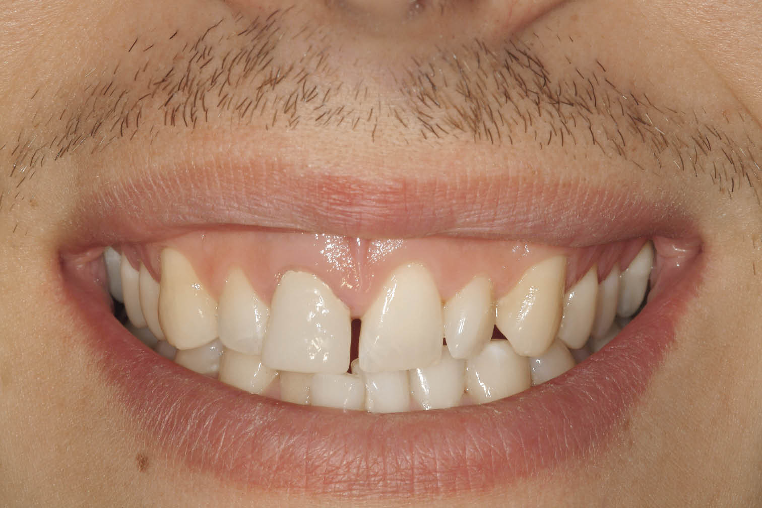
Fig 7-12 Anterior view of the patient smiling showing the high lip line and failing central incisor (No. 11).
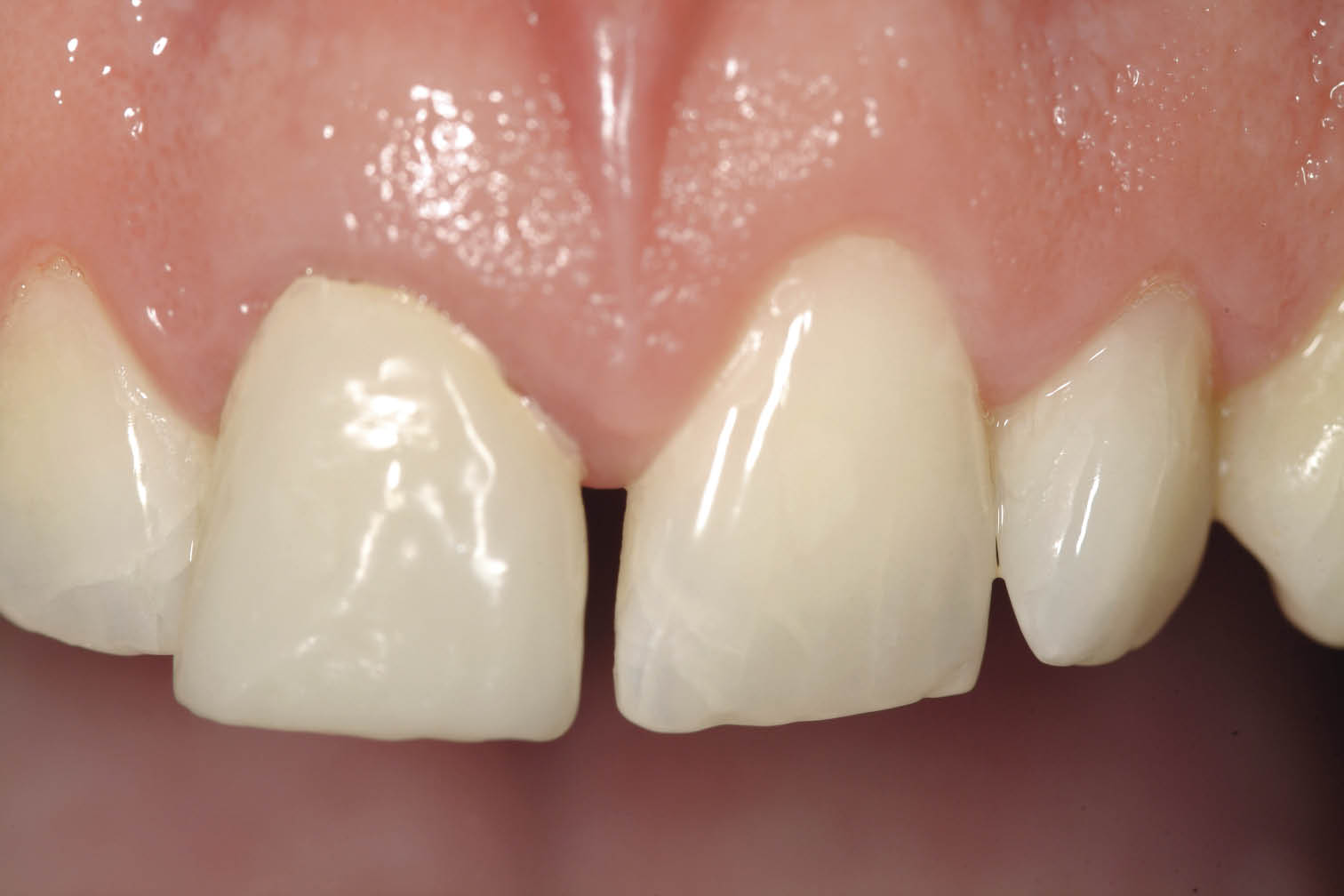
Fig 7-13 Labial view of the maxillary right central incisor area showing an acceptable level of soft tissue.
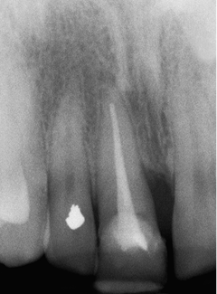
Fig 7-14 Periapical radiograph showing the previously root canal-treated failing central incisor, with a mesial bony defect visible. Abundant bone beyond the apex is visible and is sparsely trabeculated. Labial probing depths indicated an intact socket with a deeper pocket on the mesial aspect. The bone level adjacent to the left central incisor is adequate.
Table 7-1 Checklist for assessing a failing tooth prior to implant placement and loading
|
For immediate placement |
|
|
Symptoms |
|
|
Pathology |
|
|
Aesthetics |
|
|
Socket integrity: |
|
|
Probing |
|
|
Fistulae |
|
|
Dehiscences |
|
|
Bone level |
|
|
Density |
|
|
Root anatomy |
|
|
Root inclination |
|
|
Interdental space |
|
|
Root width |
|
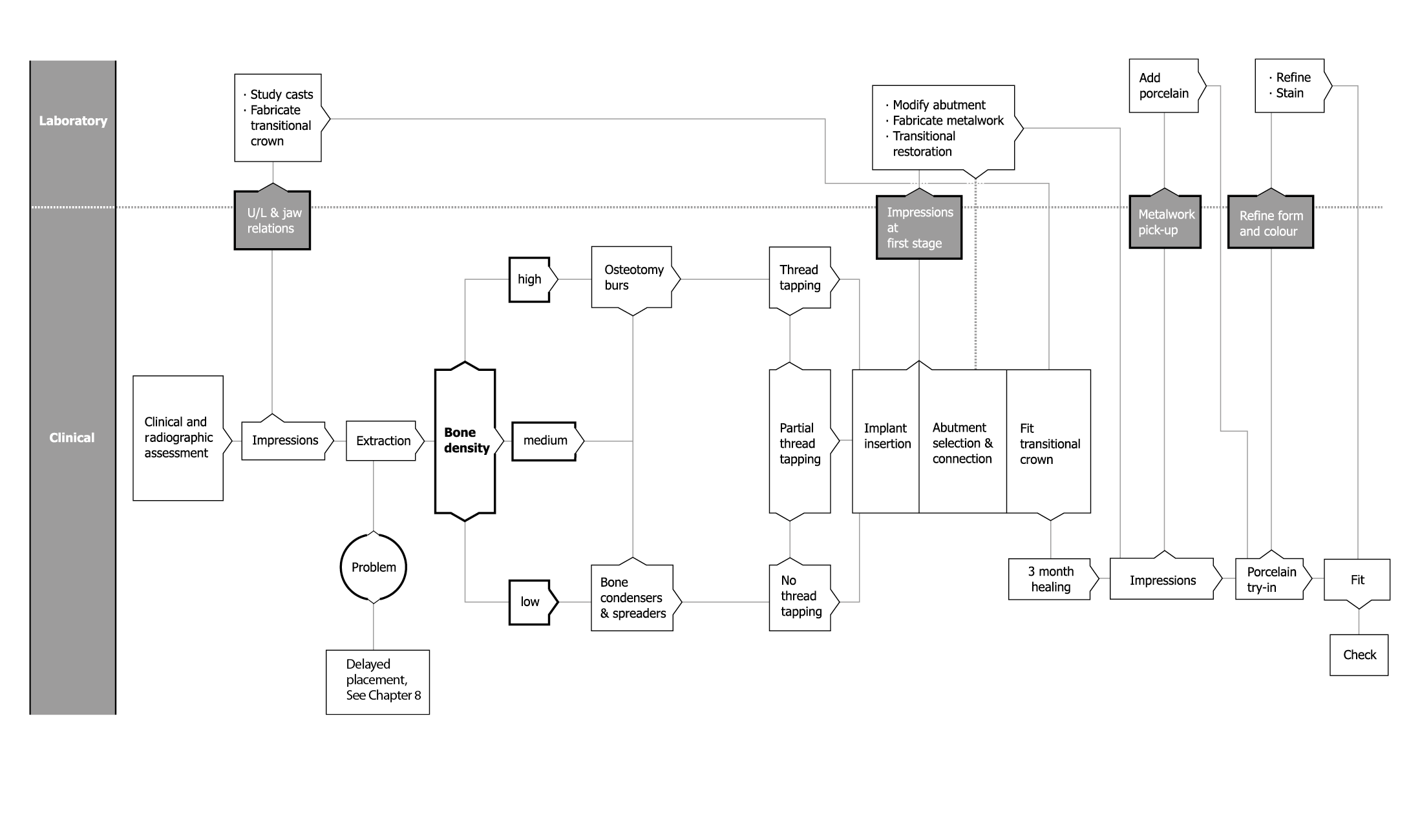
Flowchart 7-2 Immediate placement and loading: Clinical stages
Preoperative Stage
Preoperative impressions are taken for the construction of a provisional restoration (Figs 7-15–7-17). Upper and lower alginate impressions are taken in addition to the registration of the relationship of the jaws in maximum intercuspation. Facebow recordings are recommended, where appropriate, to transfer information relating to the position of the condyles, as well as condylar and tooth guidance.
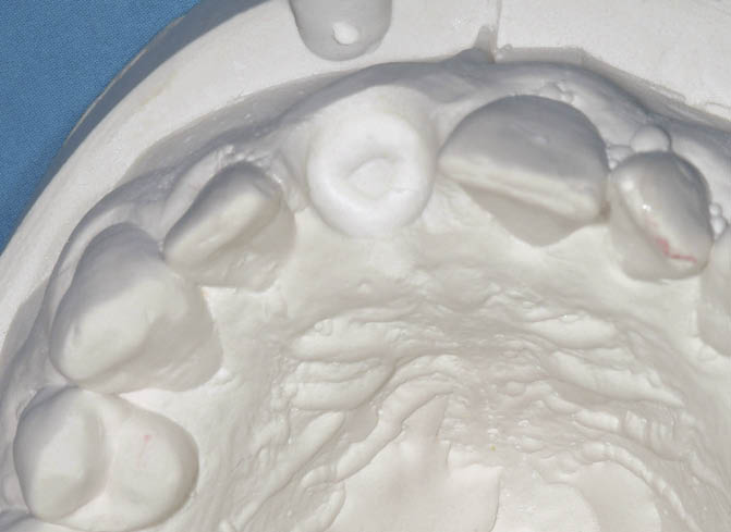
Fig 7-15 Model with the right central incisor removed and socketed to a depth of 2 mm for the fabrication of the transitional restoration, which will fit within the socket of the extracted tooth.
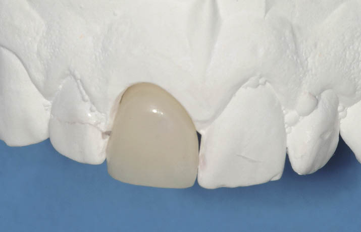
Fig 7-16 Hollow transitional restoration made out of acrylic resin, which will also be used to define the prosthetic envelope to select the abutment during implant placement.
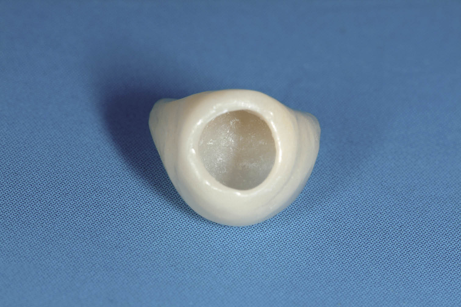
Fig 7-17 View of fit surface of the hollow transitional restoration, which will seal the extraction socket after adaptation to the abutment.
Extraction
During extraction of a tooth, the integrity of the socket must be maintained. Extraction forceps with fine beaks may be used in addition to root elevators. However, these are often used in conjunction with a periotome, whose fine blade enables the tooth to be separated from the socket by severing the periodontal ligament.61,77 Access for the periotome to the mesial and distal part of the root is facilitated by removing the interdental contact point (Fig 7-18). Care must always be taken to avoid damaging the labial plate, which is often most fragile in the anterior region (Fig 7-19). Access for the application of extraction forceps can be facilitated by removing excessive contours of the clinical crown. This prevents damage to the soft tissues caused by the deflection of the forceps by excessive coronal contours. Single teeth with a root form resistant to removal, such as a bulbous tip or a curve, may have to be removed by sectioning the root mesiodistally in the longitudinal plane or bucco-lingually if damage to the labial plate can be prevented. In elevating the sectioned root, care must be taken not to damage the socket or interstitial bone. Teeth with multiple roots should be divided and each of the roots removed separately, using the techniques outlined above.
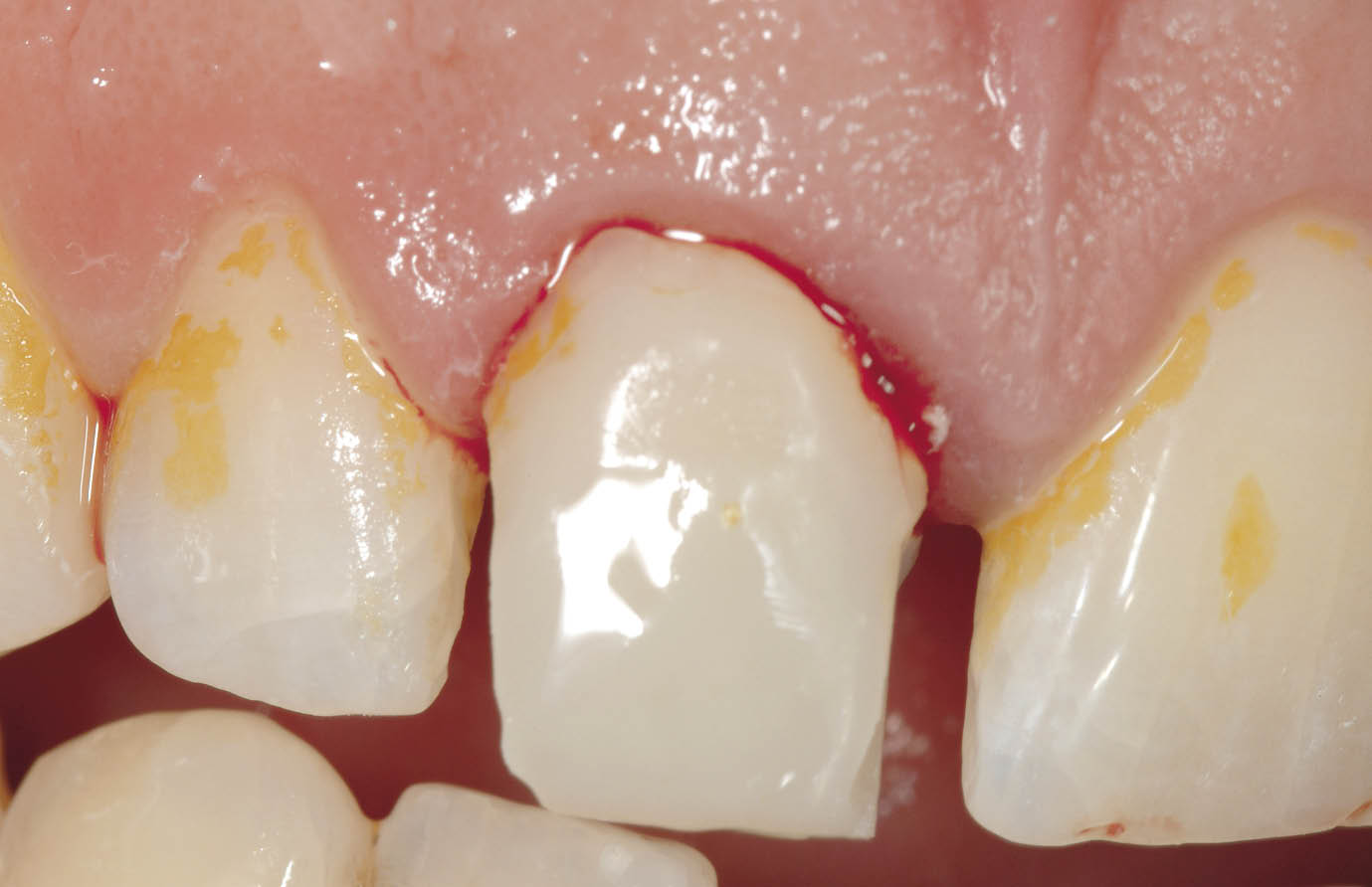
Fig 7-18 Labial view of tooth to be extracted showing removal of contact points for easy access of periotome.
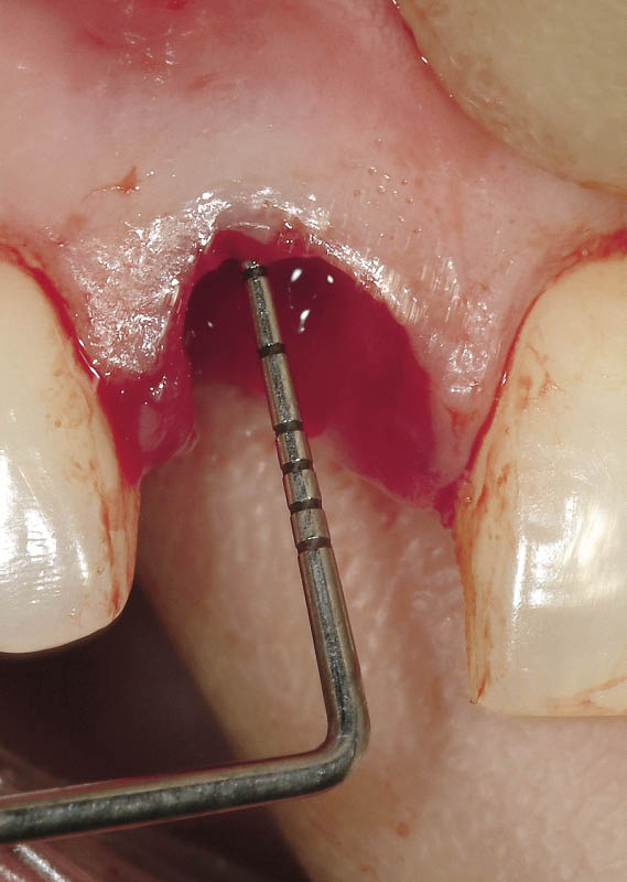
Fig 7-19 Periodontal probe being used to check the integrity of the socket. The bony socket margin is positioned less than 3 mm away from the gingival margin.
Implant Placement
Site Selection
The implant site must be selected by projecting the point where the final position of the implant is required. The aim is to obliterate as much of the socket as possible with the implant without perforating the labial or the lingual plate and without damaging any of the adjacent teeth (Figs 7-20–7-22). Typically, in the anterior maxilla, the implant site may be positioned approximately one-third of the way along the palatal wall of the socket from the apex (Fig 7-23). This will enable the osteotomy to be prepared without any dehiscence. The direction of the osteotomy should be determined using the adjacent teeth and the alveolar cortical plates as direction guides. Use of 3D imaging is particularly helpful in identifying the available bone and its relationship to the socket for accurate implant placement.
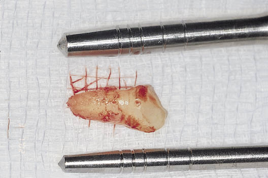
Fig 7-20 The extracted tooth alongside the bone condensers to determine the diameter of implant that will be required. The implant diameter should be wide enough to maximise the space available within the socket to gain primary stability, be one millimetre away from the labial aspect of the socket and yet avoid perforation of the cortical plates.
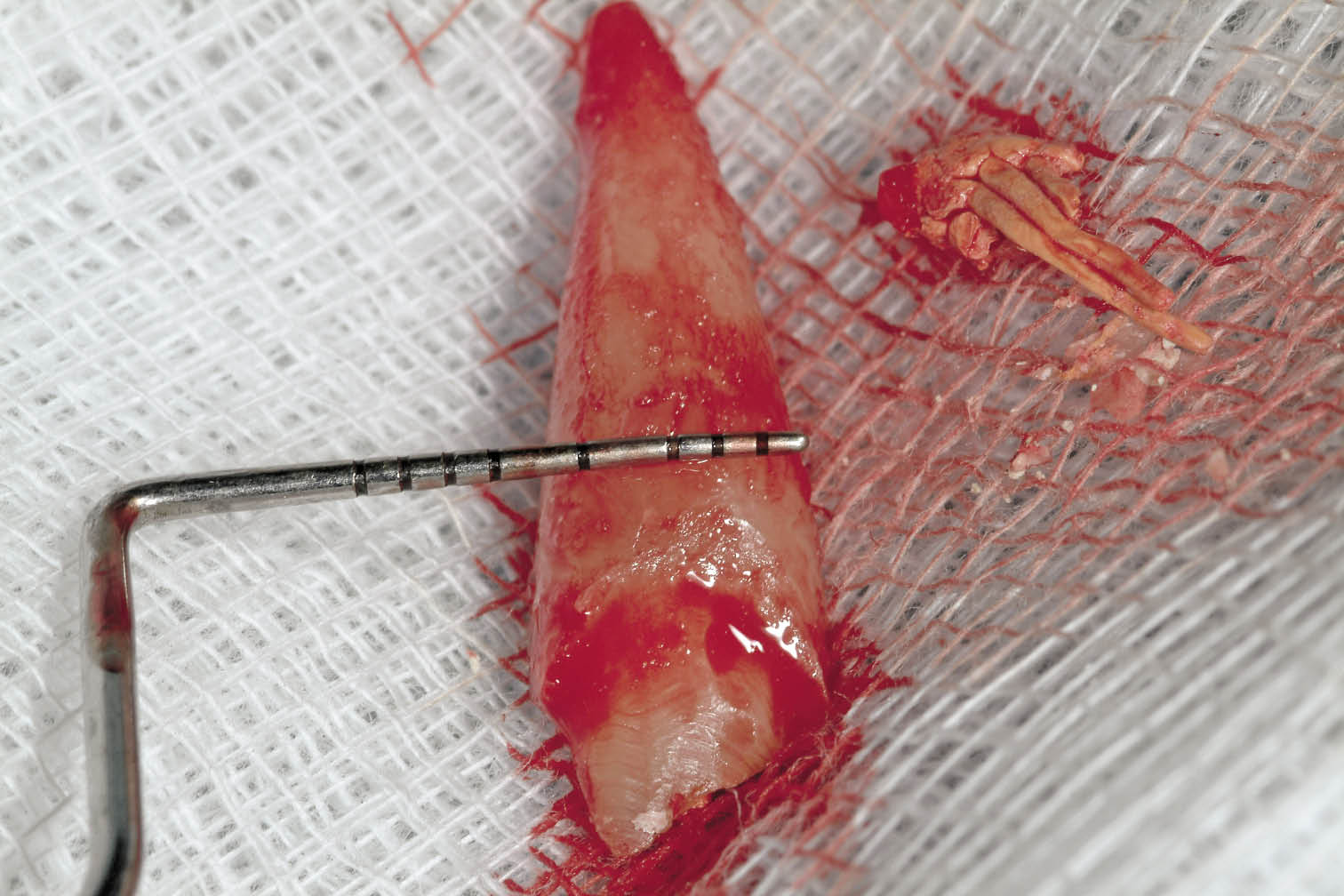
Fig 7-21 Periodontal probe measuring the root width along the height of the bony crest of the socket to estimate the implant diameter and residual space.
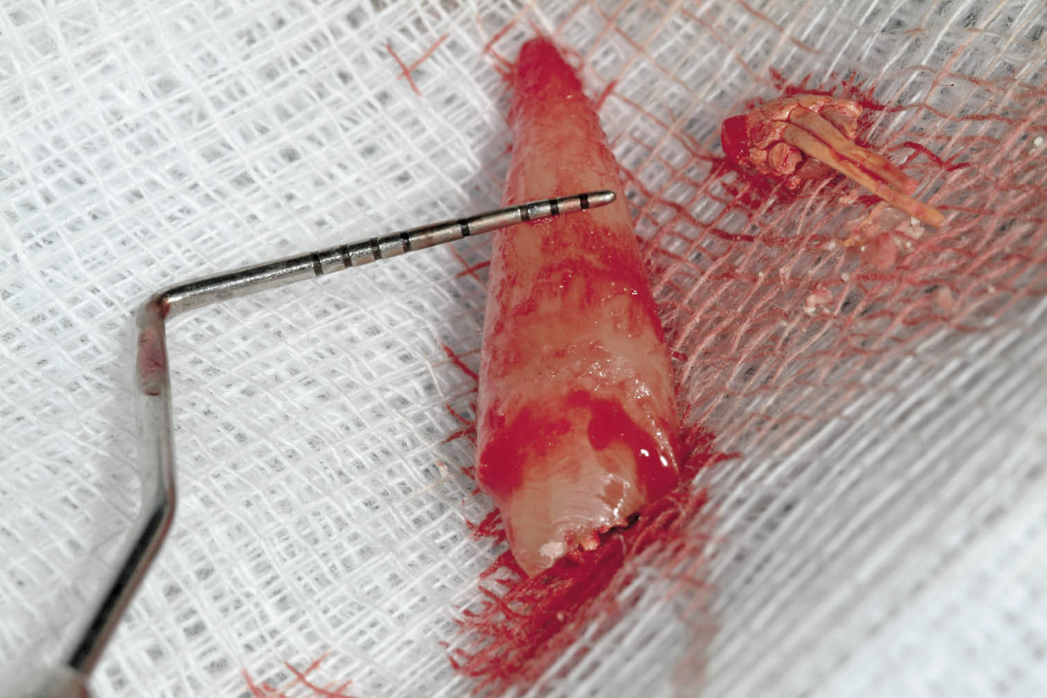
Fig 7-22 Measurement of the root diameter midway along its length establishing implant diameter to be 4.5 mm for adequate primary stability and sufficient space to prevent damage to the labial plate at the crest.
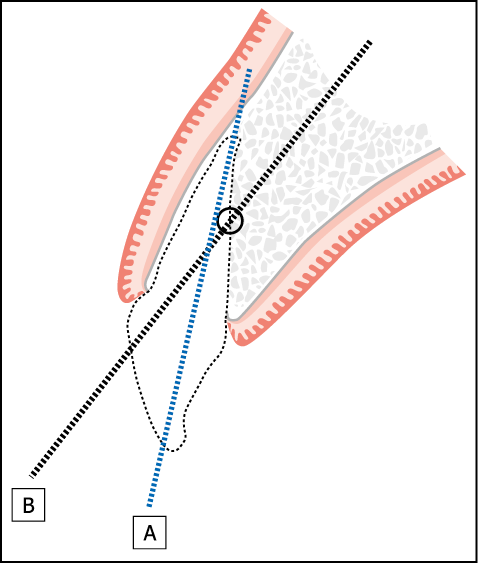
Fig 7-23 Immediate implant placement following the extraction of central incisor. Diagram depicts the ideal point of entry into the extraction socket at a point one-third to one-half from the apex. The direction of line B depicts the direction of osteotomy. Line A demonstrates the inevitable perforation through the labial plate if the osteotomy is directed through the apex.
Osteotomy Preparation
A small round bur or a position marker is used at the beginning of the procedure to determine the centre of the osteotomy (Fig 7-24). The position marker may now be used to extend the osteotomy to the predetermined depth based on radiographic measurements. Alternatively, a pilot bur (Lindemann bur) may be used. This will provide an indication of the density of the bone or may confirm the results of a previous CT scan. The diameter of the osteotomy is then enlarged until it matches the core diameter of the implant (Figs 7-25 and 7-26). In bone of low density in the maxilla it is preferable to use bone condensers to ensure that the osteotomy is carried out with a minimal risk of perforation of the labial or lingual plates. Furthermore, the use of bone condensers increases bone density and the bone-to-implant contact during the early phase of healing, at which stage stability and the prevention of excessive micro-movement is critical.78,79 The use of bone condensers is not recommended in the mandible. However, bone spreaders may be used for the same purpose. If resistance is met during the initial stages of osteotomy preparation, it is preferable to use osteotomy burs. Palpation of the buccal and palatal tissues gives an early indication of any inadvertent perforation by a misdirected osteotomy bur. The osteotomy is prepared to a depth that allows the selected implant to be placed approximately 1.5 mm below the level of the labial wall of the socket (Fig 7-27). Variations in preparation will occur depending on the bone density.
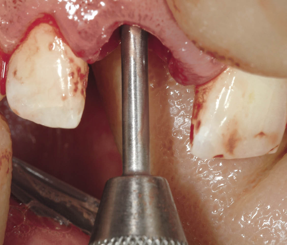
Fig 7-24 Position marker being used to select site and direction of the future implant.
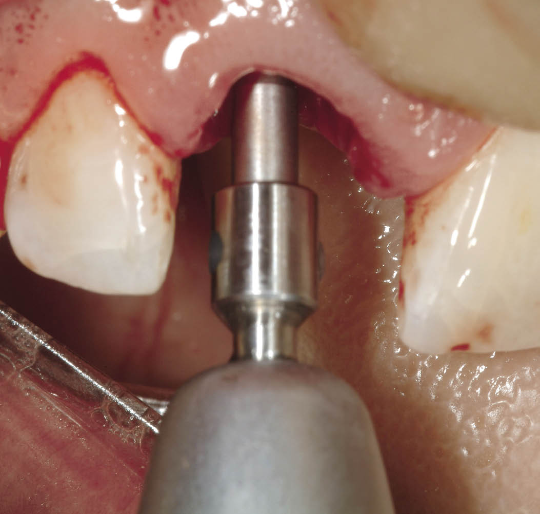
Fig 7-25 Lindemann bur used to establish direction and confirm density of residual bone beyond the socket.
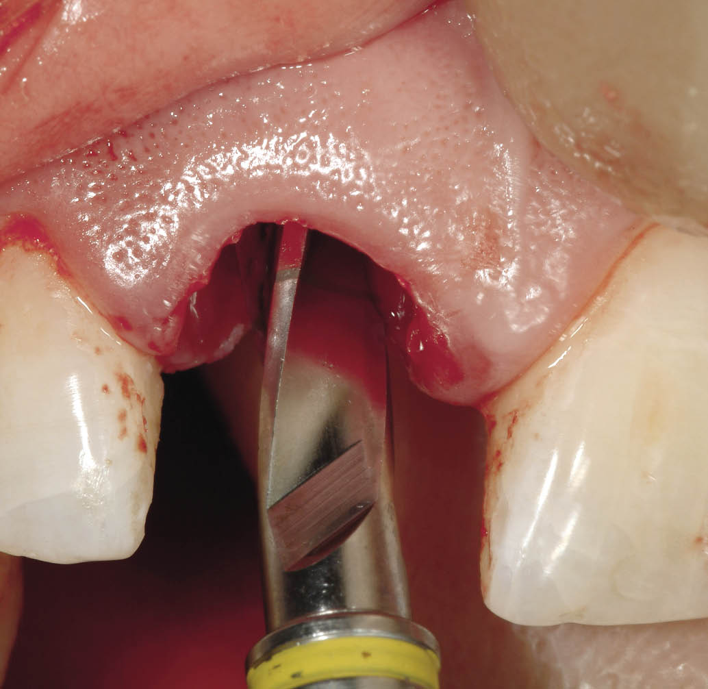
Fig 7-26 Final osteotomy bur (4 mm diameter for 4.5-mm implant) following the sequential enlargement of the osteotomy.
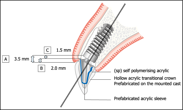
Fig 7-27 Example of positioning of implant. Depth of implant placement (A = 3.5 mm) below the labial gingival margin is given by B (gingival thickness determined by probing depth) plus C (depth of implant placement below the labial bony socket crest).
- • Low-density bone. The implant may be inserted without any further development of the osteotomy. If excessive resistance is met during the insertion of the implant, the implant should be unscrewed and inserted after partial tapping of the threads.
- • High-density bone. The bed for the implant must be formed completely. This may involve the use of any hand reamers and bone taps required by the implant system that is being used.
- • Moderate-density bone. A hand reamer may be used and the osteotomy partly threaded with a bone tap before insertion of the implant.
This variation in osteotomy preparation will ensure that adequate primary stability for the implant can be achieved for immediate loading.
Implant Insertion
The implant is inserted using the clinical experience and judgement of the operator to ensure that there is no damage to the implant, bone or insertion device from using excessive force, and yet the implant is secure enough to be able to withstand immediate loading (Fig 7-28). This will vary from system to system. The depth to which the implant is inserted should be sufficient to allow the creation of an emergence profile that is aesthetically acceptable (Fig 7-29). The required depth can be estimated by measuring the thickness of the labial gingiva from the margin to the level of the bone and adding it to the depth to which the implant should be inserted below the bony crest (1.5 mm). With the Ankylos implant system (Dentsply Friadent, Mannheim, Germany) the implant carrier with its circumferential ring and other features can be used as a gauge to estimate the depth of the implant insertion.
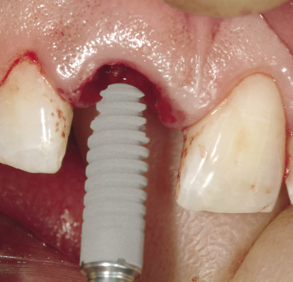
Fig 7-28 A 14-mm implant being inserted after the use of the final osteotomy bur. A precisely fitting self-tapping implant will provide high primary stability for immediate loading.
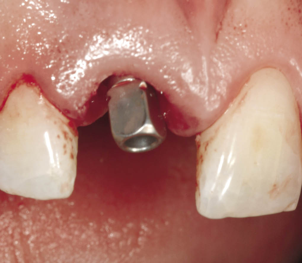
Fig 7-29 The implant is seated. The depth and angulation to which it has been placed can be seen from the structure and orientation of the implant carrier.
It is well known that bacteria can induce inflammatory bone loss depending on local and systemic factors.80–85 We believe that if the implant is to be placed below the level of the bone the connection between the implant and abutment should be sufficiently tight to prevent leakage of microbial endotoxins and other virulent factors. Most of the known interfaces between implant and abutment carry the risk of microbial leakage, which may be a contributory factor to inflammatory bone loss.86–89
Leakage can be prevented or minimised by the use of silicone sealants or cements. However, they may deteriorate or dissolve.90,91 Alternatively, a high-precision conical connection (Fig 7-30) can provide a tight seal, which may prevent micro-leakage, as demonstrated by vacuum tests of preassembled components.92 This should be maintainable under functional load to prevent the loss of bone in an area that is critical for aesthetics.93 Mechanical load testing demonstrates a significant superiority of a conical connection, which acts by preventing gap formation caused by movement between implant and abutment.94 Tests to demonstrate leakage must be properly conceived. Inoculation or penetration tests are only valid if a preassembled abutment–implant complex is tested.87 Inoculation and subsequent assembly of the implant–abutment complex has the obvious drawback of overspill during assembly or contamination of internal or external surfaces of the connection. This may lead to fallacious conclusions with regard to penetration tightness.95,96
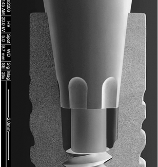
Fig 7-30 Scanning electron microscope shows the seal between abutment and implant provided by the high accuracy of the component parts. This seal prevents microbial leakage, which is significant because of the positioning of the junction below the level of the bone. Please note the presence of an index on the abutment, which may or may not be used as an index, can limit the number of positions of engagement. However, the tight conical connection still is functional for anti-rotation as well as acting as an antibacterial seal.
The implant should ideally be positioned to maximise on a good aesthetic outcome. A space of approximately 1 mm from the labial surface is desirable (Fig 7-31). This will compensate for any remodelling that may take place. The use of a micro-structured implant surface enables contact osteogenesis and improves bone-to-implant contact in comparison with machined surfaces.97–99
Figures 7-31 to 7-45 demonstrate the clinical management of an implant placed subcrestally and restored using a tight conical connection with a zirconium oxide abutment.
Where there is a thin bone biotype, the addition of a biomaterial may be considered. The choice of a non-resorbable or slowly resorbing material is likely to provide stability and support for the soft tissues.100
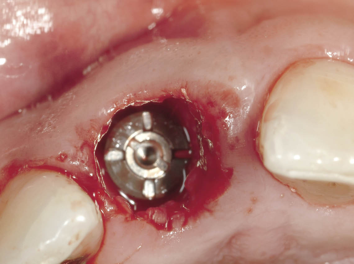
Fig 7-31 Occlusal view of the implant in situ, showing its position in relation to the socket walls, particularly to the labial plate. The formation of a blood clot is the first stage in bone regeneration and will need to be retained by the transitional restoration.
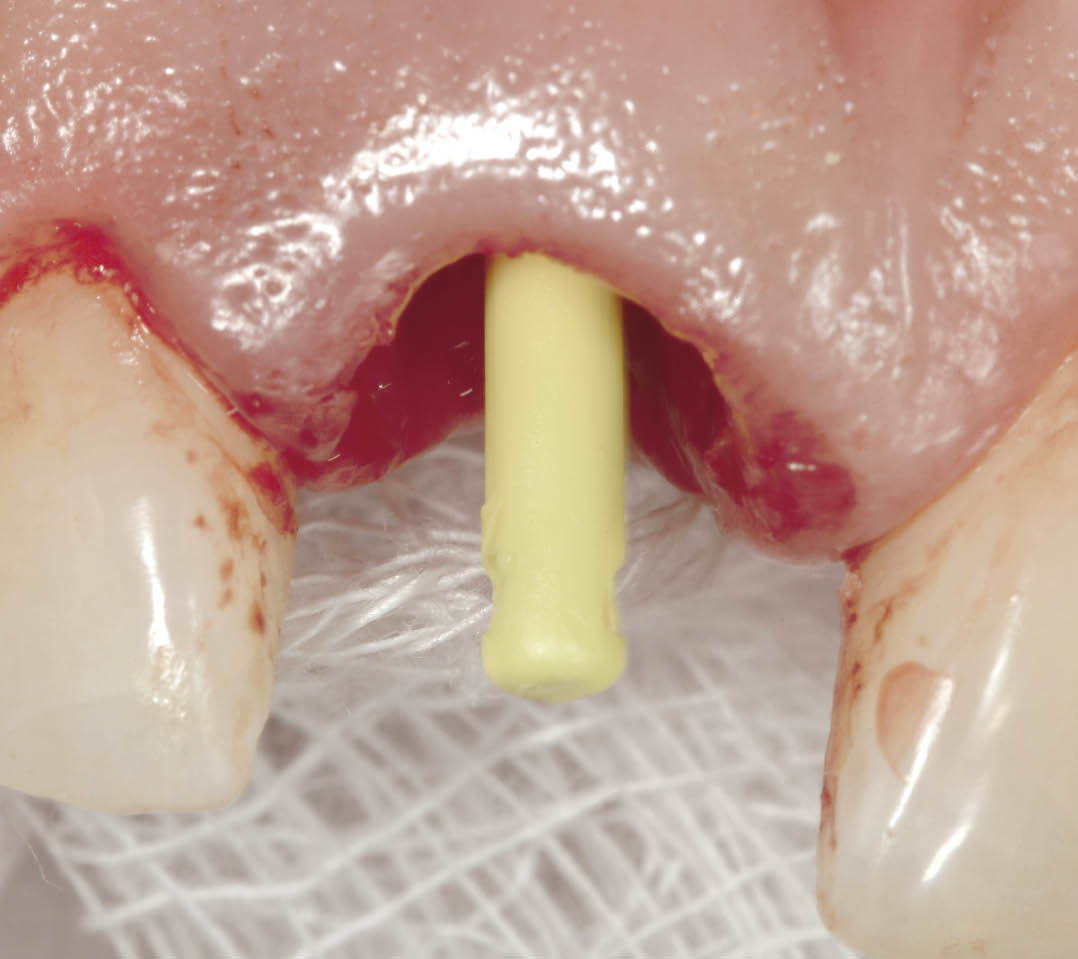
Fig 7-32 Direction indicator being used to select the abutment. Alternatively a trial abutment can be used to estimate the angle (e.g. Ankylos CX implant).
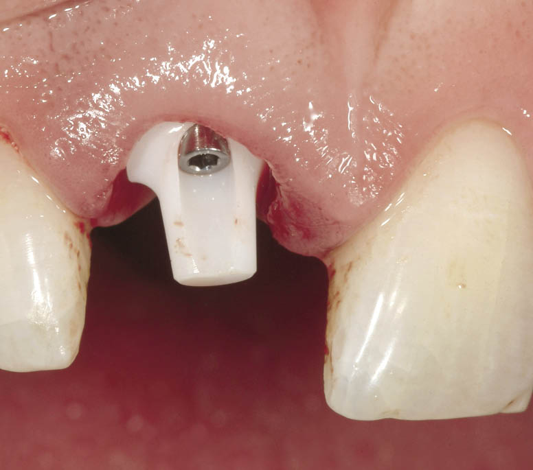
Fig 7-33 A 15-degree zirconium oxide abutment is selected and tried in. It is tightened with light finger pressure and disengaged to assess any interference with the alveolar socket. Rapid engagement on tightening combined with sudden disengagement following loosening of the screw is indicative of an absence of interference with the socket.
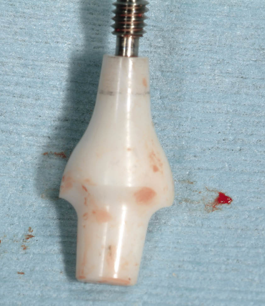
Fig 7-34 Following disengagement of the ceramic abutment, it is removed from the mouth and examined for a continuous grey line around the margin, which will signify that it was indeed properly seated without any deflection caused by the tooth socket. If the grey line is incomplete, seating of the abutment was prevented by interference adjacent to the region where the grey line is missing, and this will require modification of the abutment until the ring is complete.
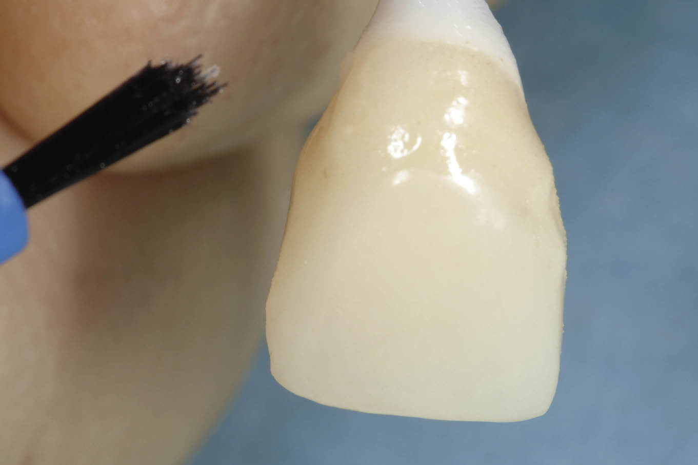
Fig 7-35 The transitional restoration is adapted using autopolymerising acrylic resin with the abutment in situ. The abutment is removed and any minor discrepancies can be corrected extraorally.
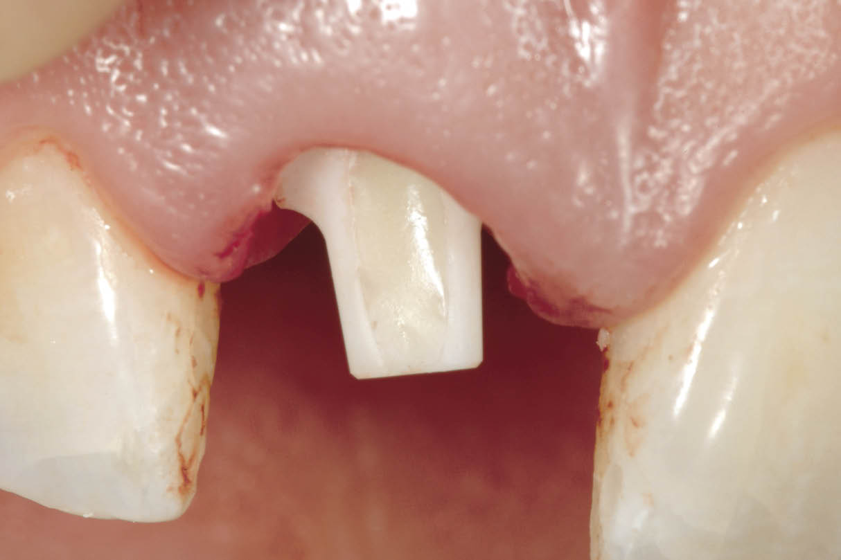
Fig 7-36 The abutment is then seated and its orientation confirmed using the transitional restoration. Wax is used to seal the hex of the screw followed by a glass-ionomer cement to occlude the screw access hole. This allows a predictable amount of cement to be used to avoid excess.
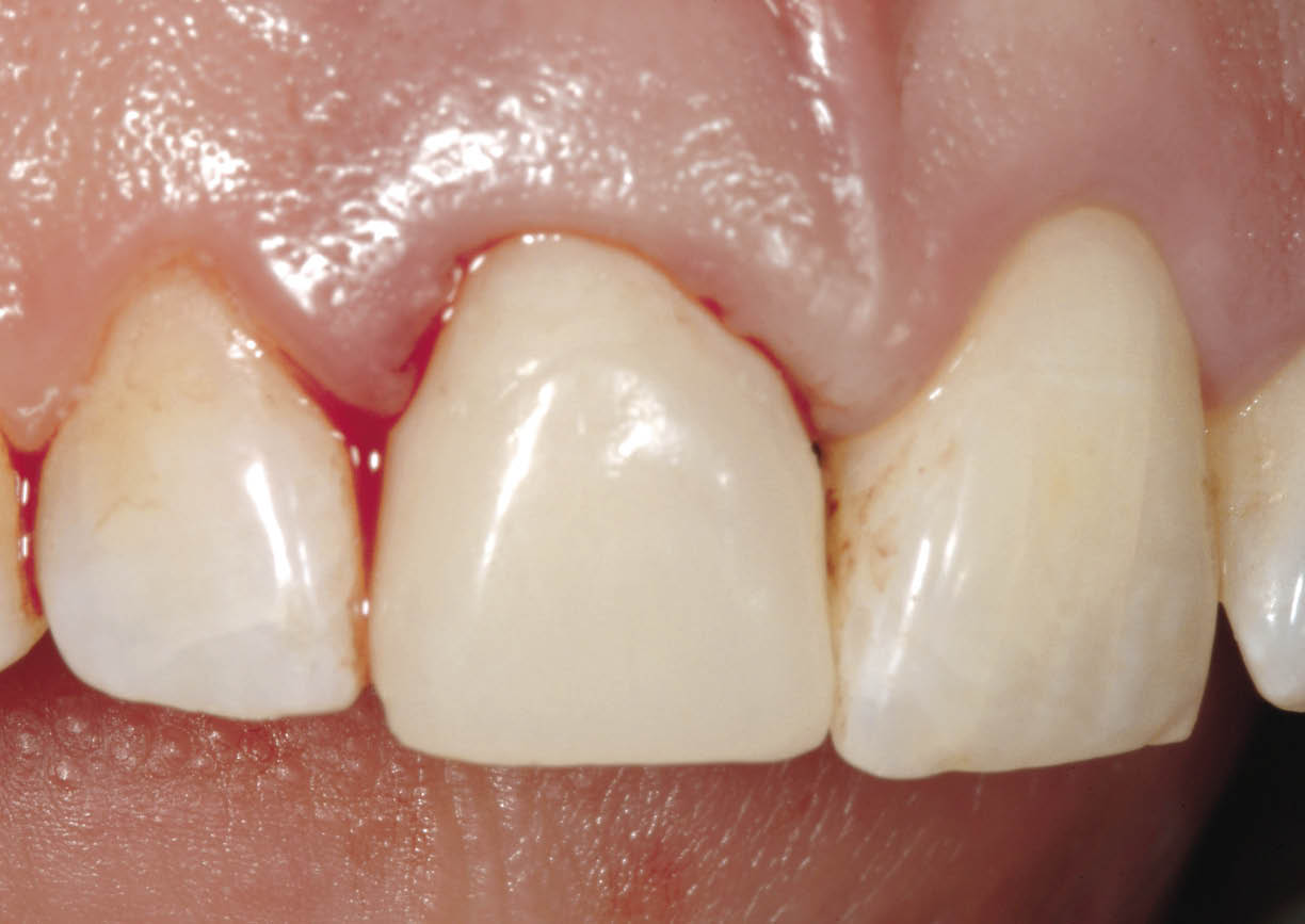
Fig 7-37 The transitional restoration cemented with a soft cement (Temp Bond; Kerr, West Collins, CA, USA). The transitional restoration has been constructed on a study cast to fit to 1 mm below the gingival margin and in contact with the soft tissues. This provides support and prevents the soft tissues from collapsing.
Fig 7-38 Immediate post-operative periapical radiograph showing the abutment engaged to the implant. The bone levels can be seen in relation to the implant and the abutment. Note the absence of bone in the region of the implant-abutment interface. No excess cement is visible.
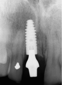
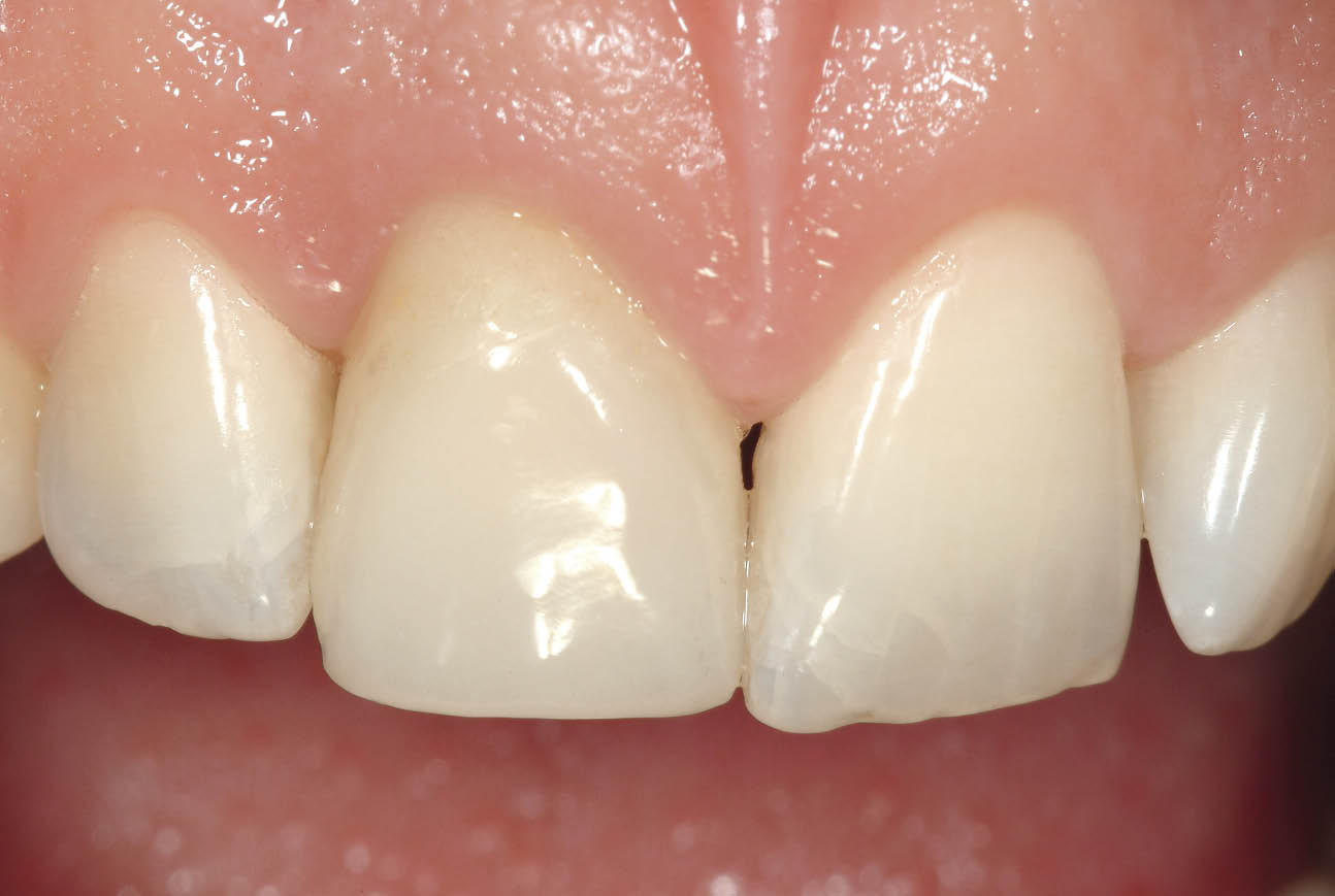
Fig 7-39 Clinical appearance of the transitional restoration at three months after insertion showing stable healed and healthy soft tissues. Note the transitional restoration has been constructed shorter to avoid contact in protrusive excursions.
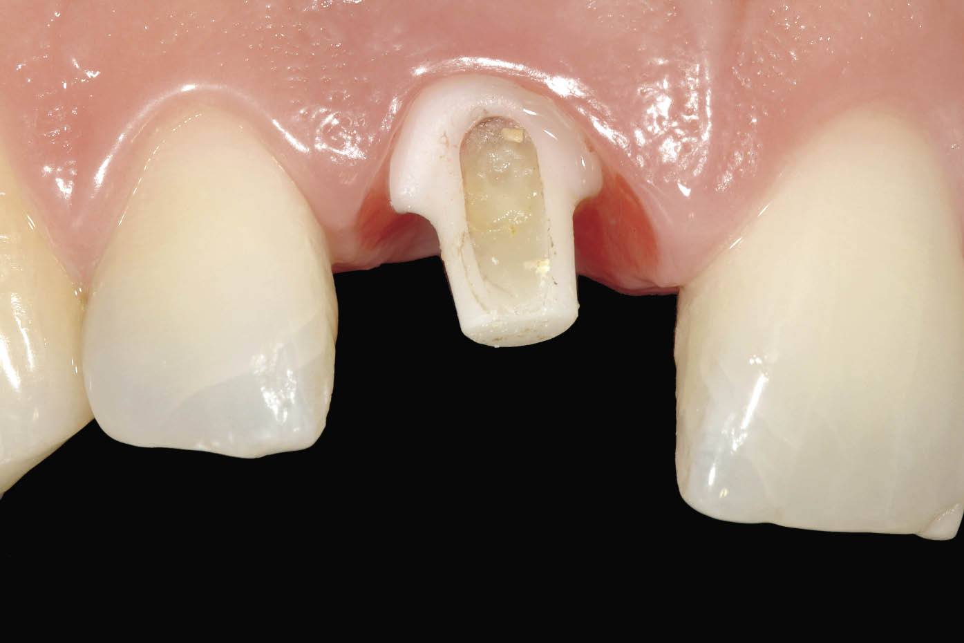
Fig 7-40 Labial view of the abutment after removal of the transitional restoration prior to conventional impression taking using fine retraction cord and addition cured impression material. Note the proximity of the margin to the soft tissues resulting from the use of a larger and scalloped ceramic abutment.
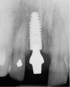
Fig 7-41 Periapical radiograph taken three months following implant insertion showing clearly the development of bone above the implant and approximating the abutment. This is indicative of a tight implant-abutment connection and the absence of micro-leakage.
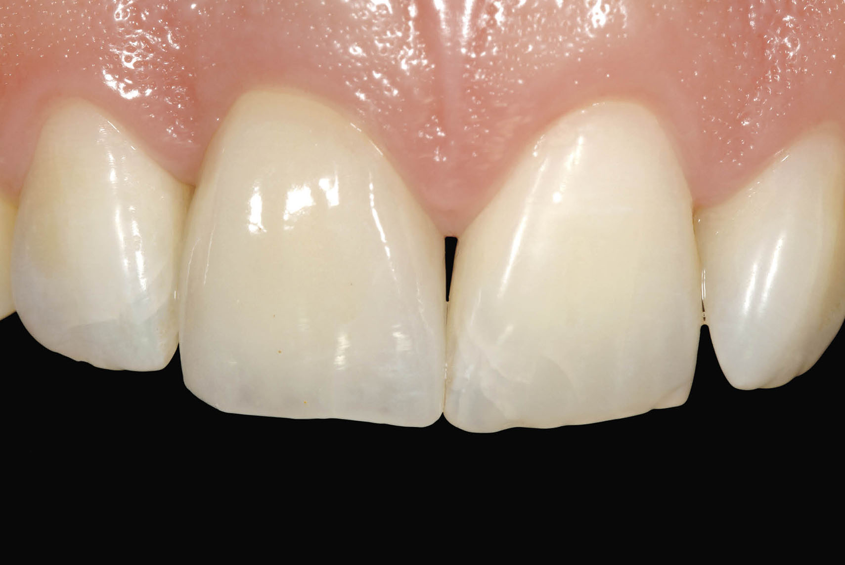
Fig 7-42 Definitive restoration in situ 6 months following implant insertion showing harmonious soft tissue contours and excellent reproduction of tooth form and colour using a zirconium oxide coping veneered with porcelain.
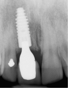
Fig 7-43 Periapical radiograph taken six months after insertion showing further development of bone above the implant and in apparent contact with the abutment. Note the maturation of bone around the adjacent central incisor.
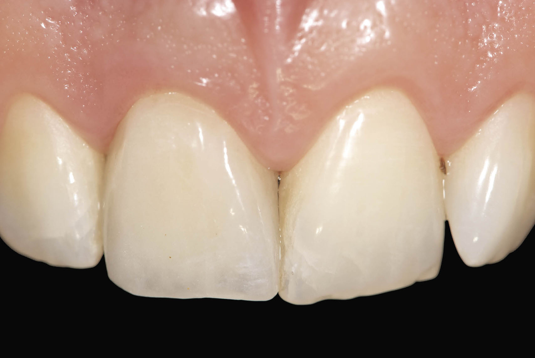
Fig 7-44 Clinical appearance two years after the procedure showing stable soft tissue contours. In addition the development of the interdental papilla can be seen.
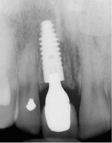
Fig 7-45 Periapical radiograph taken two years after the procedure. Note the increase in bone overlying the implant and in contact with the abutment. Further development of bone adjacent to the left central incisor can be seen and could be assumed to have provided support for the generation of the papilla. Stable bone levels are fundamental to stable soft tissue contours and may be contributed to a micro-textured implant surface in combination with a tight conical connection between implant and abutment.
Impressions at First Stage
Impressions at first-stage surgery can be taken to transfer the implant position to the laboratory for the restorative phase (Figs 7-46–7-50). The clinical and laboratory details of this technique will be addressed in the appropriate section. This impression can also be used for the fabrication of the transitional restoration in the surgery to be fitted at the same visit. Impressions at first-stage surgery are particularly indicated in cases of delayed loading. It enables the clinician to prepare for second-stage surgery.
Fig 7-46 A customised impression tray for an open-tray technique.
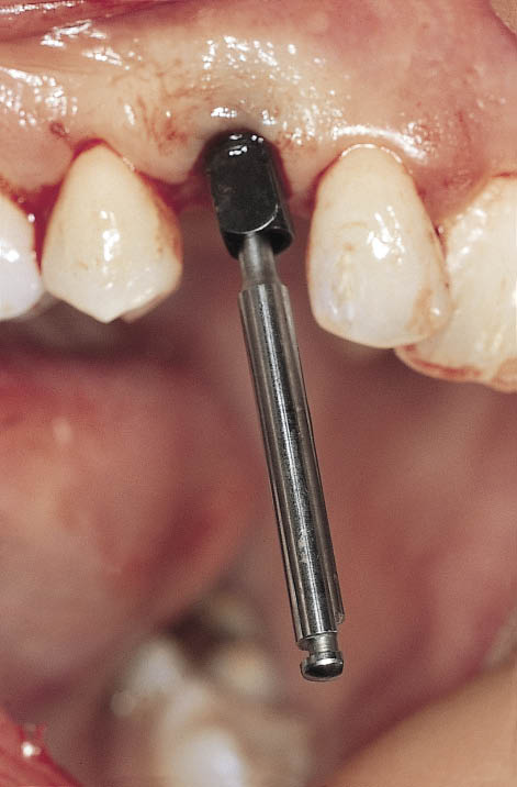
Fig 7-47 A hex driver inserted into the implant carrier prior to seating of the impression. The design of the carrier is suitable for transferring the implant position using an open-tray impression technique.
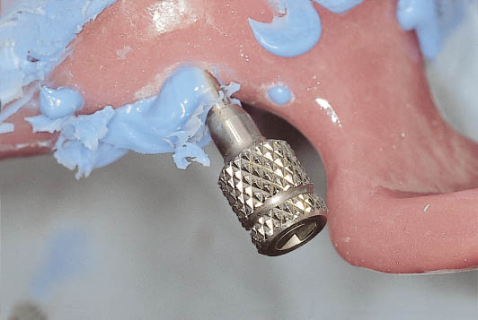
Fig 7-48 The impression tray in situ with the handle attached to the hex driver prior to disengagement of the implant carrier.
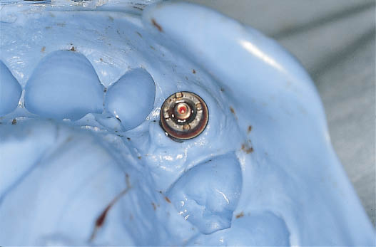
Fig 7-49 Impression tray after removal from the mouth. The implant carrier is visible secure within the impression, avoiding the need for reinsertion inaccuracies.
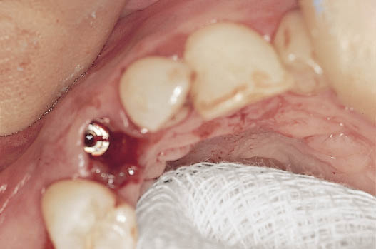
Fig 7-50 The implant is visible within the socket following the removal of the implant carrier. The decision as to how to proceed can be implemented. Immediate loading using a provisional abutment can be carried out. Alternatively soft tissue closure can be performed. A further option is to seal the blood clot in the socket and support the soft tissues using a provisional restoration such as a Rochette bridge. A modified sulcus former may be used to provide ease of access at the time of bringing the implant into function.
Delayed Loading: Clinical Management
If primary stability is not considered sufficient to load the implant immediately, some measures must be taken to minimise the risk of failure or complications.
Preserving Soft Tissue Architecture
The use of a pontic to maintain and support the soft tissue contours is the primary method of choice. This requires an accurately fitting pontic, which will obliterate the margin of the socket, providing a seal for the protection of the blood clot. Ideally a fixed restoration such as a metal-acrylic resin Rochette bridge may be used. Attachment of a sulcus former or healing abutment will facilitate location of the implant at the time of loading. Alternatively, in a non-aesthetic region, the clinician may choose to use a sulcus former that has been modified to contain the blood clot.
Wound Closure
Several methods to close the wound over immediately placed implants are available. These are described below.
Vascularised Pedicled Flaps
Because vascularised pedicled flaps have a blood supply they have a relatively low chance of breakdown.
- • The palatal pedicled flap. This is the flap of choice for closure of an immediate implant site in the anterior maxilla. Its vascularised nature makes it very predictable. Furthermore, it may be used to increase the amount of soft tissue bulk in this region without compromising the amount, texture or colour of the attached keratinised gingiva (Fig 7-51).
- • The labial coronally advanced flap. This has the disadvantage of advancing the buccal attached gingiva to close the wound, resulting in a reduction of the attached keratinised gingiva around the implant.
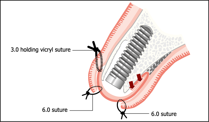
Fig 7-51 Pedicled flap from the palate may be used to close over the socket (see section on soft tissue surgery).
Free Non-vascularised Grafts
Grafts that are non-vascularised are less predictable and more prone to breakdown.
- • Composite grafts. These include gingival and connective tissue and may be used as a plug to cover the implant. They are designed to fit exactly into the socket and derive their blood supply from the socket margins. They retain the colour and texture of the epithelial tissue of origin (Fig 7-52).
- • Connective tissue grafts. These do not have the epithelial component and are generally placed underneath the partially mobilised margins of the surrounding soft tissue, which provides the blood supply for the graft (Fig 7-53).
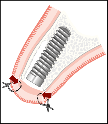
Fig 7-52 Circular free gingival graft sutured to socket soft tissue margins. The source of reestablishment of blood supply is indicated by the arrows.
Fig 7-53 Subepithelial connective tissue graft may be used as described in the section on soft tissue surgery. Re-establishment of the blood supply will depend on the contact area indicated by arrows. Occlusive membranes (for instance, TefGen, Lifecore Biomedical, Chaska, MN, USA) may also be used in a similar way.
Occluding Membranes
Occluding membranes are non-permeable and are placed over the socket and tucked under the socket margins. They permit connective tissue to form underneath the membrane; they are removed after approximately four weeks, enabling epithelialisation of the underlying connective tissue to proceed. Resorbable membranes (collagen based) may be used in a similar manner and permit epithelialisation onto the membrane.
Immediate Loading: Clinical Management
It is not intended to provide a specific prescription for the assessment of primary stability. The decision to carry out immediate loading will depend upon the clinical judgement, understanding and experience of the clinician. Factors to be considered will be discussed later within this chapter under ‘Immediate Loading: Primary Stability’.
Abutment Selection and Attachment
After removal of the implant carrier, the appropriate abutment can be selected. Some implant systems offer direction indicators or trial abutments to facilitate this. The hollow transitional restoration can be used to confirm the angulation and sulcus depth of the required abutment based on the depth of the implant (Fig 7-54, see also 7-32). The definitive abutment is selected, modified if necessary and then attached to the implant using the recommended torque.
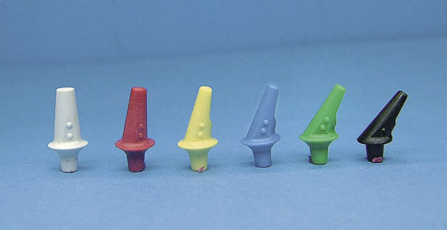
Fig 7-54 Range of trial abutments, which are available in different sulcus heights and fit directly into the conical connection of the Ankylos system. These are graduated at 7.5-degree increments and are colour coded corresponding to the abutments. The colour codes represent the angles as follows: white, 0 degrees; red, 7.5 degrees; yellow, 15 degrees; blue, 22.5 degrees; green, 30 degrees; and black, 37.5 degrees. The sequence of colours may be memorised as it corresponds to the sequence of colour codes used for the implant diameters (Ankylos system).
Prefabricated Angled Titanium Abutments
The availability of a range of prefabricated angled titanium abutments is particularly well suited to the selection of the correct abutment and its attachment to the implant without substantial modifications. The availability of six angles and four sulcus depths enables most clinical needs to be met. The considerable advantage of a narrow abutment is the ease with which it can be attached to the implant without interfering with the socket. At the same time, it will re/>
Stay updated, free dental videos. Join our Telegram channel
VIDEdental - Online dental courses


