Delivery of N2O/O2 Sedation
CHAPTER OBJECTIVES
Upon completion of this chapter, the reader should be able to:
1. Appreciate the history and evolution of N2O/O2 sedation delivery equipment.
2. Understand the differences between a central gas and portable gas supply system.
3. Identify each component and its purpose in the N2O/O2 sedation delivery system.
4. Recognize variations of N2O/O2 sedation delivery systems.
5. Identify the safety features found on the N2O/O2 sedation delivery system.
Nitrous oxide/oxygen delivery systems have evolved dramatically since their inception. Equipment manufacturers have diligently pursued ways to enhance the patient experience while maintaining a focus on a safe environment for the operator. New products continue to enter the market as the interest in effective and efficient N2O/O2 sedation continues and/or surges in a variety of professions. The future of how this method of patient management is delivered remains to be seen.
1 Manufacturers of N2O/O2 Sedation Equipment
A. Two major companies in the United States manufacture and distribute N2O/O2 delivery systems. They are, in alphabetical order: Accutron, Inc., Phoenix, Arizona, and Porter Instrument Co.—A Division of Parker Hannifin Inc., Hatfield, Pennsylvania. The sedation product line Matrx by Midmark out of Orchard Park, New York, continues under the Parker Hannifin, Inc., corporation.
B. Authors’ note: We can personally attest to the genuine concern of each of these companies to manufacture the best and safest products for the mutual benefit of both patient and clinician.
2 Delivery of N2O/O2
A. History and Evolution of N2O/O2 Delivery Equipment
1. N2O/O2 sedation equipment has evolved dramatically since the initial delivery through a bladder bag for Horace Wells.
2. Many years after Wells’ anesthetic discovery, the idea of mixing oxygen with nitrous oxide was considered. Edmund Andrews suggested that 20% oxygen be used because that was the amount proportionate to room air.1 Sir Fredrick Hewitt in 1887 was also a pioneer who incorporated oxygen into a machine that delivered both gases.2
3. Early machines were designed as intermittent (demand) flow, meaning flow was released upon demand or inspiration by the patient.2 Current machines typically used in an ambulatory setting use a continuous-flow design.
4. A pivotal point in the progression of this technology was the addition of the fail-safe O2 mechanism in the mid-1970s. This device prevented the delivery of 100% N2O and ensured that no less than 21% O2 (O2 concentration in ambient air) would ever be delivered to the patient.3 Today this tolerance is 30%.
5. Mr. Gary Porter, president of Porter Instrument Co., Inc., played an integral role in the evolution of the early analgesia-sedation units. The Porter Instrument Co.—A Division of Parker Hannifin—is the only company to manufacture the flowmeter glass tubes found in sedation units and hospital anesthesia machines around the world.
6. Today we enjoy the amenities of audible alarms, digital readouts, tactile-sensitive features, and high-quality performance.
B. Central Gas Supply System
1. A central gas supply system is an option for practitioners who prefer N2O/O2 sedation availability in several units as a “built-in” system within the facility.
a. This system is preferred when there is a high frequency of N2O/O2 use and/or users because there are cost-saving, convenience, and space-saving features.4
b. The central system is most conveniently and effectively used when it is incorporated as part of the architectural design of the operatory (Figure 7-1).
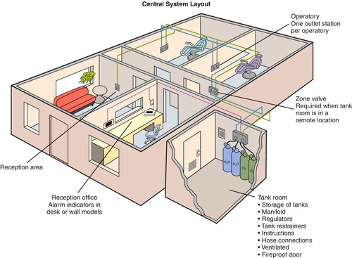
c. The National Fire Protection Agency (NFPA) has established standards and guidelines for the equipment installation in healthcare facilities. Professional installation of a central supply sedation system is mandatory to ensure all codes are met. Guidelines can be found in NFPA publications.5,6
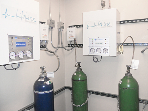
2. The hub of a central gas supply system is its manifold (Figure 7-2). The manifold is a device that connects several large cylinders of gas together and ensures the constant availability of gas to each individual operatory through copper lines within the walls of the building.
a. Manifolds are designed to supply gas to as many as 10 units in a given facility. Beyond 10 units, the facility is considered a hospital care unit and is regulated accordingly.
b. A manifold will also transfer the gas supply from one tank to another when the previous tank is depleted.4
c. A manifold can be operated either manually or automatically. The NFPA recommends that an automatic system be in place when gas is stored a significant distance from the treatment area such as on another floor.
3. For the gas to be dispensed safely, there must be a means for reducing the amount of pressure from the cylinder. Regulators and pressure-reducing valves serve this purpose in order to ensure safe delivery of gas through the equipment and to the patient.
a. The high pressures of 750 psi in the N2O tank and 2000 psi in the O2 tank are first reduced to lower pressures of approximately 50 psi by regulators commonly found on or near the cylinders of central supply delivery systems.
b. Pressure is further reduced within the flowmeter to local atmospheric pressure.
4. Pressure gauges on the manifold indicate the amount of pressure in the lines to the operatories, which should be within 20% of 50 psi.
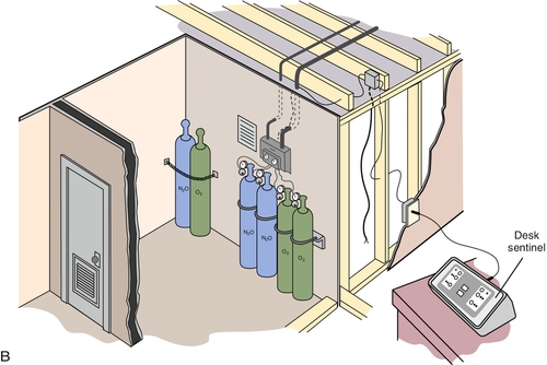
5. The newest manifolds have several safety features built into the system.
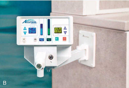
a. Alarm systems, both visual and audible, alert a designated person if the pressure of the gas falls below 40 psi or becomes greater than 60 psi. A wall alarm or a desk alarm located in a central location alerts practitioners when the system needs attention (Figure 7-3, A and B).
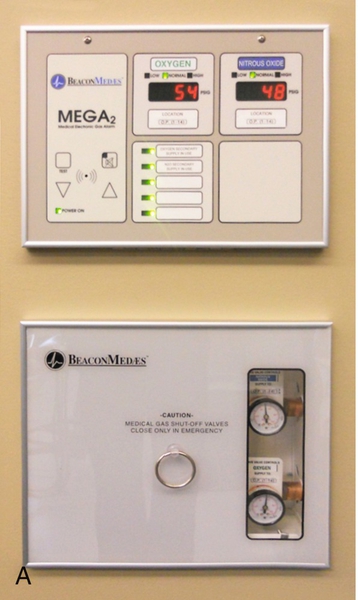
b. Pressure-relief valves exhaust any gas with a pressure greater than 75 psi.
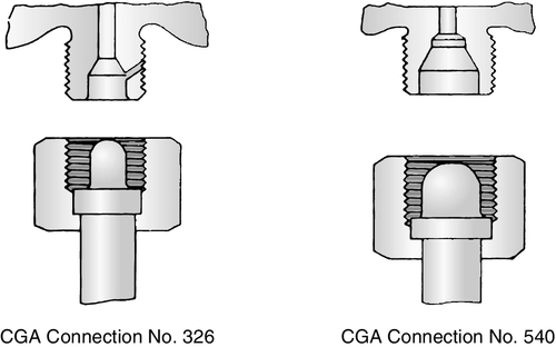
6. Large G and H cylinders are used in central supply systems. Another safety feature is located within the threaded valves that open the cylinders. Threaded stems are designed to fit into specific cylinders only, thus preventing the cylinders from being filled with the wrong gas (Figure 7-4).
7. All gas from the manifold travels through precleaned, degreased copper tubing, and all connections are silver-soldered at 1000 ° F. The piping system must be pressure tested with N2 (air) for 24 hours at no less than 150 psi before patient use. Tubing and piping lines for the delivery of O2 are ½ inch, while 3⁄8-inch tubing and piping lines is the norm for N2O (see Figure 7-5). The difference in pipe size prohibits the inadvertent crossing of lines. However, at least one fatality has occurred because of installation errors and subsequent delivery of 100% N2O instead of O2. Piping, Industry, Progress, and Education (PIPE) is an organization dedicated to educating users of N2O/O2 sedation about the proper installation of the system. Disclaimer: Seek professional installation for all sedation equipment to ensure all current specifications and codes are met.
C. Portable Gas Delivery System
1. A portable gas delivery system is often used when N2O/O2 sedation is not used frequently. The unit houses smaller tanks and may be moved easily to different locations within a facility.4
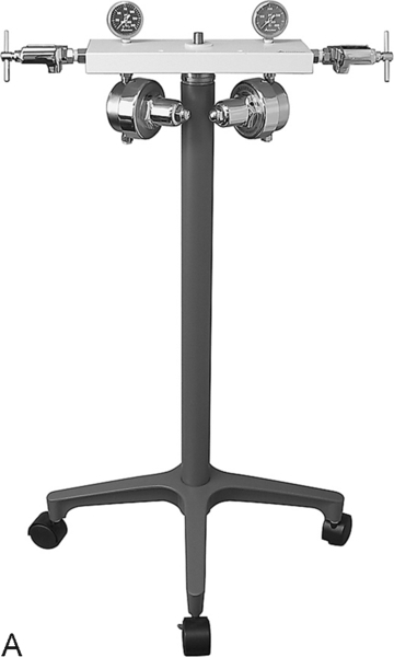
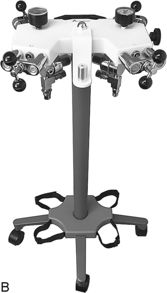
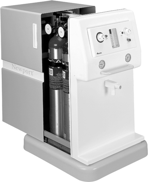
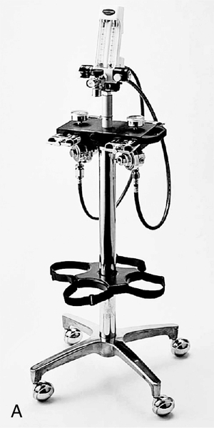
2. The yoke stand of the portable machine is the backbone and supporting structure on which the equipment rests. Stands vary slightly in style; all are easily transportable on wheels. Some stands hold two tanks, whereas others hold four tanks (Figure 7-6). One company markets a portable system that encloses the yoke and tanks for aesthetic appeal (Figure 7-7).
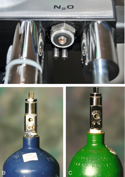
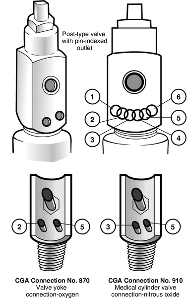
3. The yoke is the metal framework adjoining the stand to which the cylinders are attached. There is an attachment configuration for the cylinder to match to be correctly attached to the unit. Metal pins, specifically arranged, protrude from the yoke onto which the cylinder is fitted (Figure 7-8). This precise mechanism is designed to prevent the incorrect cylinder attachment to the yoke and is known as the pin index safety system (Figure 7-9).
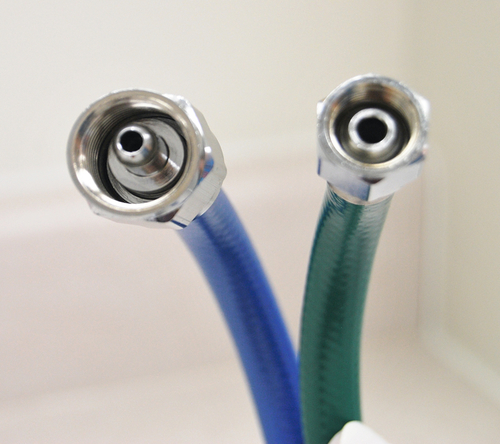
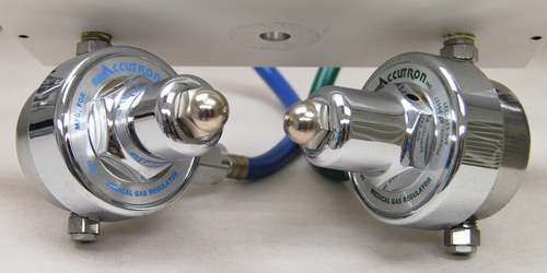
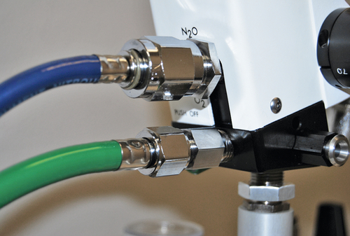
4. Regulators are found on portable systems similar to central delivery systems (Figure 7-10). Gas reduced to 50 psi is delivered through hosing connected to the back of the flowmeter, which is the boxlike portion of the unit with parts such as switches and knobs (Figure 7-11). Hoses from the regulator to the flowmeter are often color-coded, respectively, for the gases and, again, purposely vary in size and threaded-end connections to prevent incorrect gas flow to the machine.
5. At this point, the equipment is the same whether delivering gas from a central supply or a portable unit.
D. Flowmeter
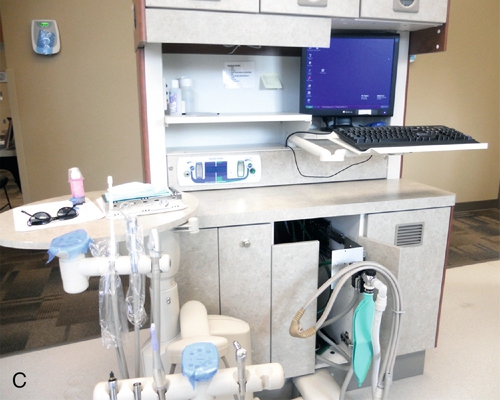
1. The flowmeter is the highly calibrated device that sits on top of the yoke assembly, is mounted to an arm or on the wall, or is located within the cabinetry (Figure 7-12). Gas flows from the cylinder through the flowmeter. The flowmeter indicates the amount of gas being delivered to the patient.
Stay updated, free dental videos. Join our Telegram channel
VIDEdental - Online dental courses


