Chapter 6. Basic instrumentation in endodontics
B.S. Chong
CHAPTER CONTENTS
Summary71
Introduction72
Basic instrument pack72
Irrigant delivery devices84
Loupes, fibre-optic and operating microscopes91
Learning outcomes91
References92
SUMMARY
Clinicians have to remain up-to-date in the fast evolving world of everyday practice. Newer materials, innovative techniques and novel devices are continually being developed by manufacturers to facilitate the clinical practice of endodontics. Released onto the market, often promising simpler, quicker and better results, the hope is that it will allow the management of even the most challenging cases. In this chapter, the basic instruments and essential devices needed in clinical endodontic practice are identified and described. The equipment necessary for rubber dam application, instruments for access cavity and root canal preparation, devices to determine working length and deliver irrigants, instruments for retrieving broken instruments and posts, and for filling root canals are covered. Storage and sterilization of endodontic instruments, and the advantages of enhanced illumination and magnification are also explained.
INTRODUCTION
The principles of root canal treatment consist of thorough cleaning, adequate shaping and complete filling of the root canal system. In order to accomplish these objectives, many different instruments are available. Some of the instruments are common to all branches of dentistry while others have been modified or are specifically designed for endodontics.
BASIC INSTRUMENT PACK
For convenience, a basic selection of instruments should be packaged or set-up in a tray, ready to use (Fig. 6.1). A front-surfaced mouth mirror produces an undistorted image for good visibility deep within the pulp chamber. The endodontic explorer is a double-ended, extra-long, sharp instrument designed to help in the location of canal entrances and for detecting fractures. A long spoon excavator is required to remove pulpal contents and soft caries where present. Locking tweezers are ideal for handling paper points, gutta-percha points, cotton wool pellets and root canal instruments. Both Briault and periodontal probes are necessary for the initial assessment of the tooth for caries and the localized periodontal condition. A flat plastic instrument and an amalgam plugger are needed for placement of an inter-appointment restoration. A millimetre ruler or other measuring device should be available for measuring purposes. A surgical haemostat may be used to position X-ray films, for radiography during treatment.
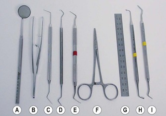 |
| Figure 6.1
(A) Front surface mirror; (B) endodontic locking tweezers; (C) DG16 endodontic explorer; (D) Briault probe; (E) long-shank excavator; (F) surgical haemostat; (G) millimetre ruler; (H) amalgam plugger; (I) flat plastic.
|
RUBBER DAM
It is a prerequisite that the tooth being treated must be isolated; this is effectively and efficiently achieved by the use of rubber dam. There are many good reasons for using rubber dam:
• It protects the patient from inhalation or ingestion of instruments, medicaments and debris.
• It prevents infection by providing a clean, dry, aseptic working field, free from salivary contamination.
• It allows retraction of soft tissues and the tongue so as not to obstruct the operating field and also protect them from injury.
• It enhances access thereby improving the efficiency of treatment.
• It provides better patient comfort without the oral cavity being flooded with water and/or debris.
Rubber dam is available in pre-cut (commonly 150 mm) squares and also in a roll. The sheets come in different colours and thickness (thin, medium, heavy, extra heavy and special heavy); some are even scented. The thicker material has the advantage of a tighter fit around the neck of the tooth, thus providing a more hermetic seal, so floss ligatures may not be required. It is also less likely to tear1 and offers better protection for the underlying soft tissues. If there is a small amount of seepage around the margins between the tooth and the rubber dam, temporary filling material (e.g. Cavit, 3M ESPE, Neuss, Germany) or a non-setting caulking agent (Oraseal, Ultradent, South Jordan, UT, USA) (Fig. 6.2) may be placed to seal off the leakage. For patients allergic to latex, non-latex rubber dam, made of silicone (e.g. Flexi Dam, Roeko, Coltène/Whaledent, Langenau, Germany) (Fig. 6.3) is also obtainable. The other items for the application of rubber dam include the following.
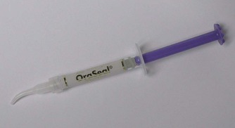 |
| Figure 6.2
OraSeal caulking agent, a non-setting sealant.
|
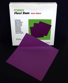 |
| Figure 6.3
Flexi Dam, a non-latex rubber dam.
|
Rubber dam punch
A punch is used to make the required numbers of holes depending on the teeth to be isolated. Usually single tooth isolation is all that is required for endodontic treatment. Single-hole punches (Dentsply Ash, Weybridge, Surrey, UK) are available which will cut a neat hole (1.63 or 1.93 mm), while those with a rotatable table (Ainsworth pattern) will cut different sized holes ranging in diameter from 0.5 to 2.5 mm (Fig. 6.4). Whichever is chosen, it is important to ensure that the punch is sharp, so as to produce a clean hole without any residual tags on the rubber dam. Otherwise, the rubber dam will tear when stretched and applied to the tooth. The size of hole that is punched is also important; the ease of application with a larger hole must be balanced by the quality of the seal at the cervical margin.
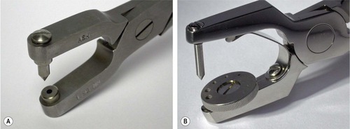 |
| Figure 6.4
Rubber dam punch: (A) Ash single hole; (B) Ainsworth.
|
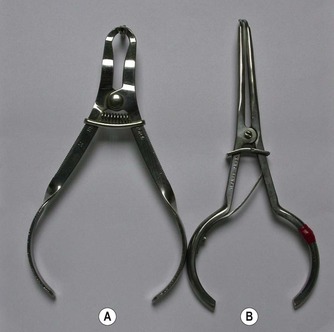
Rubber dam clamp
There are many different designs of rubber dam clamp to cater for every possible situation. However, there are no standards governing the manufacture of rubber dam clamps. 2
Clamps have two uses: first, they anchor the rubber dam to the tooth, and second, they retract the gingivae. In endodontics, anchorage is the main requirement. Most clamps are made from stainless steel; some are made from plated steel, which may be more susceptible to corrosion by sodium hypochlorite. There are also non-metallic clamps made of plastic (SoftClamp, KerrHawe, Bioggio, Switzerland) on the market. Clamps are winged or wingless, retentive or bland (Fig. 6.5). A winged clamp allows the attachment of the rubber dam to the clamp so that both clamp and rubber dam may be applied to the tooth together. Retentive clamps are designed to make a four-point contact with the tooth; they have narrow, curved and slightly inverted jaws, which may displace gingival tissue to grip the tooth below the level of greatest circumference; they are very useful on partly erupted teeth. Bland clamps are less likely to impinge on the gingivae as they have flat jaws, which grip the tooth around its entire circumference. However, they can only be used where a tooth is fully erupted and has a cervical constriction that prevents the clamp from slipping off.
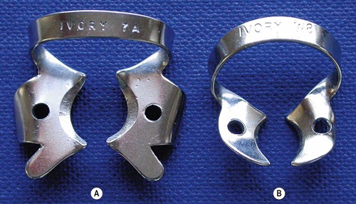 |
| Figure 6.5
Rubber dam clamps: (A) winged clamp with bland jaws (7A); (B) wingless clamp with retentive jaws (W8).
|
A basic assortment of clamps may consist of the following (Fig. 6.6): Ivory pattern 00, 0, 1, 2A, 9, W8A, 14 and 14A. The wingless W8A, the winged 14 and 14A are for molars, the 2A and 1 for premolars, and the 9 for incisors. A range of lettered Ash clamps, which are generally smaller, may also be used; the winged K and E for molars and premolars respectively, and the wingless EW for incisors and broken down premolars. The EW clamp gives better access than the 9 clamp. The fracture or unexpected dislodgement of a rubber dam clamp is probably the only serious risk associated with rubber dam usage. The risk of inhaling or swallowing the fractured or dislodged clamp may be minimized if it can be retrieved. A length of floss should be tied to one of the holes in the jaw of the clamp and then knotted, it is then wound around the bow of the clamp, threaded through the other hole in the opposite jaw and tied again (Fig. 6.7).
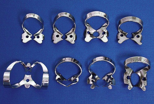 |
| Figure 6.6
A basic assortment of clamps. Top row, left to right: Ivory patterns 00, 0, 1, 2A. Bottom row: Ivory patterns 9, W8A, 14, 14A.
|
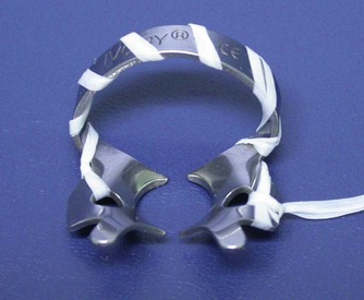 |
| Figure 6.7
Dental floss tied onto the rubber dam clamp to aid retrieval in case of fracture or dislodgement.
|
In anterior teeth, it is sometimes possible to secure the rubber dam without the use of clamps. The interproximal spaces may be wedged with wooden wedges, strips of rubber dam or short lengths of specially made latex or non-latex cords (Wedjets, Hygenic, Coltène/Whaledent, Cuyahoga Falls, OH, USA) (Fig. 6.8).
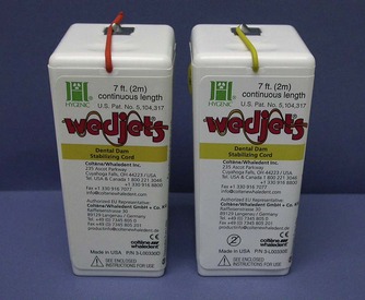 |
| Figure 6.8
Wedjets rubber dam stabilising cords.
|
Clamp forceps
Several types are available including the University of Washington/Stoke, Ivory (Heraeus Kulzer, South Bend, IN, USA) (Fig. 6.9) and Brewer (Dentsply Ash) patterns; the choice is a matter of personal preference. The forceps are used to place, adjust and remove the rubber dam clamp. Some forceps may require adjustment to their working ends prior to first use. If the ends are too large, they need to be reshaped so that it is less difficult to disengage the clamp on the tooth.
 |
| Figure 6.9
Rubber dam forceps: (A) Ivory; (B) University of Washington/Stokes.
|
Rubber dam frame
The corners of the rubber dam are held apart on a frame, stretched over the patient’s mouth, so as not to obscure the operator’s vision and not to be uncomfortable for the patient. Rubber dam frames come in various sizes and designs; they are shaped so that they do not impinge on the patient’s face. Rubber dam frames are made from either metal or plastic; the latter is lighter, more comfortable and being radiolucent, removal is not always necessary when taking radiographs (Fig. 6.10). Plastic, foldable rubber dam frames (Dentsply Ash) with an articulated joint to facilitate radiography are also available.
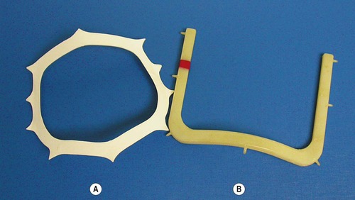 |
| Figure 6.10
Rubber dam frames: (A) Nygaard-Ostby; (B) Starlite VisiFrame.
|
Methods of application
Basically, there are three methods of application. In the first method, the rubber dam is attached to the clamp, with or without the frame beforehand, and the whole assembly placed onto the tooth. In this method, only winged clamps can be used. Once the clamp is firmly seated, a plastic instrument is used to lift the rubber off the wings to fit against the side of the tooth (Fig. 6.11). In the second method, winged or wingless clamps may be used. The clamp is placed on the tooth and the dam is then stretched over the clamp. If this technique is used, as mentioned earlier, the clamp should be wrapped in dental floss as a precaution against clamp fracture or dislodgement. In the third method, the dam is stretched over the tooth and the clamp, winged or wingless, then placed on the tooth. The assistance of a dental nurse is normally required for this method of application.
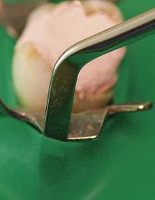 |
| Figure 6.11
After the clamp is positioned on the tooth, the rubber is lifted off the wings with a flat plastic instrument.
|
If more than one tooth is to be isolated, the rubber is knifed through each succeeding contact point. The rubber is stretched, positioned vertically above the contact point and gently forced through the point. It is important that the rubber remains as a single layer and does not fold over on contact with the teeth. Sometimes knifing is insufficient and the rubber must be forced through the contacts using dental floss. Techniques for placing rubber dam have been reviewed.3.4. and 5. The use of a lubricant on the undersurface of the dam will aid placement; brushless shaving cream or water-soluble tasteless gels are suitable lubricants.
If a tooth is broken-down and there is insufficient tooth structure for clamp placement, there are several ways of managing the problem. It is normally possible to cement an orthodontic band onto the tooth; this transforms a tooth that is difficult to isolate into one that is straightforward. It may alternatively be possible to remove enough soft tissue surgically, or by electrosurgery, to allow a clamp to be placed. Another method is the ‘split-dam’ technique in which clamps are placed on the teeth mesial and distal to it. Three holes are punched in the rubber dam and these holes are joined by cutting through with a pair of scissors. The dam is then stretched over both the mesial and distal clamps, isolating the broken-down tooth. Protection against salivary contamination is aided by the use of a cotton-wool roll placed beneath the dam buccally and an aspirator lingually, plus a caulking agent to stop any seepage. This technique may also be used for cases where bridgework is present.
INSTRUMENTS FOR ACCESS CAVITY PREPARATION
The first stage of root canal treatment is to gain entry into the pulp chamber. Several types of bur will be required for access cavity preparation (Fig. 6.12).
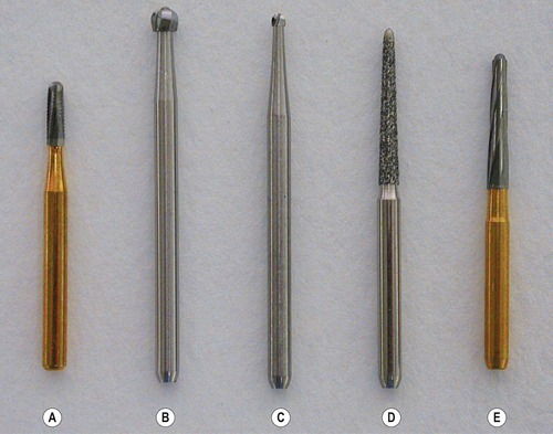 |
| Figure 6.12
Access cavity burs (left to right): (A) FG 557 ISO 010 (TC); (B) FG ISO round 018 (long); (C) FG ISO round 010 (long); (D) FG safe-ended diamond 332 ISO 018; (E) FG safe-ended TC, Endo Z (Dentsply Maillefer).
|
Burs
Friction grip burs
Friction grip tapered or cylindrical fissure burs, ISO 010 or ISO 012, are used in the initial stages of access preparation to establish the correct outline form. For penetrating ceramic or composite materials, diamond-coated burs are needed.
Round burs
Round burs, normal and extra-long, sizes ISO 010, 014 and 018, in a contra-angle handpiece are used to lift the roof off the pulp chamber and eliminate overhanging dentine. If a standard length bur is too short, burs with longer shanks, up to 28 mm, are available. So as not to obstruct vision when in use, some long neck burs have a slender shank (Hager & Meisinger, Neuss, Germany). The longer and smaller sizes of burs may be used to remove dentine when opening calcified canals.
Safe-ended burs
Following initial access to the pulp space, a safe-ended or non-cutting tip, tapered diamond or tungsten-carbide bur (e.g. Endo Z bur, Dentsply Maillefer, Ballaigues, Switzerland) (Fig. 6.12), can be used to remove the entire roof of the pulp chamber. The non-cutting tip prevents ‘gouging’ of the pulpal floor.
Gates-Glidden burs
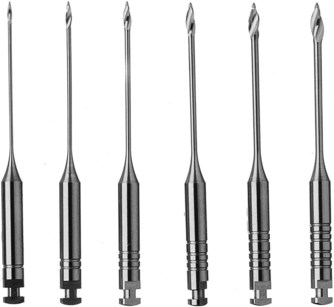
The Gates-Glidden bur has a slender shank with a cutting bulb and a pilot-tip. It is designed so that if it fractures, this will occur near the hub rather than between the shank and the cutting bulb. Gates-Glidden burs are made of stainless steel and the set of six different sizes of burs have cutting bulbs with diameter ranging 0.5–1.5 mm (Fig. 6.13). They are also available in different lengths, a standard 32 mm, a shorter 24 mm and a longer 36 mm. The Gates-Glidden bur is operated at low-speed. It may be used for coronal root canal enlargement but there is a risk of furcal perforation in mandibular molars; 6 they have largely been superseded by rotary nickel-titanium instruments (see later) for this purpose. In retreatment cases, Gates-Glidden burs may also be used to remove gutta-percha in the coronal part of the root canal.
 |
| Figure 6.13
A set of Gates-Glidden drills, sizes 1–6.
|
INSTRUMENTS FOR ROOT CANAL PREPARATION
Hand instruments
Hand instruments are grouped according to usage and to the classification established by the International Organization for Standardization (ISO). The terminology, dimensions, physical properties, measuring systems and quality control of endodontic instruments and materials are defined by these standards. As a result, endodontic hand instruments, i.e. files, reamers and barbed broaches, are standardized in relation to size, colour coding and physical properties. 7 The relevant information on sizing and colour coding for files and reamers are listed in Table 6.1; d1 is an assessment of the diameter of the working part at the tip end, and is its nominal size; d3 represents a point at 16 mm from d1 where the cutting part of the instrument ends. The taper is a constant 0.02 mm per mm of cutting flute; hence also referred to as 0.02 taper. The shape of the tip is variable. The lengths of instruments available are normally 21, 25 and 31 mm. Endodontic hand instruments have been reviewed. 8
| Size | d1 (mm) | Colour |
|---|---|---|
| 006 | 0.06 | Orange |
| 008 | 0.08 | Grey |
| 010 | 0.10 | Purple |
| 015 | 0.15 | White |
| 020 | 0.20 | Yellow |
| 025 | 0.25 | Red |
| 030 | 0.30 | Blue |
| 035 | 0.35 | Green |
| 040 | 0.40 | Black |
| 045 | 0.45 | White |
| 050 | 0.50 | Yellow |
| 055 | 0.55 | Red |
| 060 | 0.60 | Blue |
| 070 | 0.70 | Green |
| 080 | 0.80 | Black |
| 090 | 0.90 | White |
| 100 | 1.00 | Yellow |
| 110 | 1.10 | Red |
| 120 | 1.20 | Blue |
| 130 | 1.30 | Green |
| 140 | 1.40 | Black |
Barbed broaches
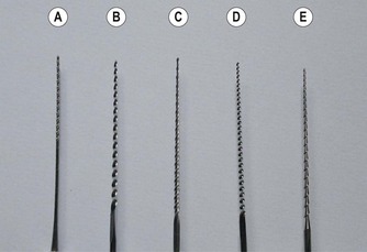
Barbed broaches are used mainly for the removal of pulp tissue from wide root canals, and cotton wool dressings from the pulp chamber. Provided the instrument is loose within the canal and is used to engage soft tissue or dressings, the risk of fracture is minimal. Barbed broaches are made from soft steel wire (Fig. 6.14). The barbs are formed by cutting into the metal and distending the cut portion away from the shaft. The cuts are made eccentrically around the shaft so that it is not weakened excessively at any one point.
 |
| Figure 6.14
Stainless steel hand instruments: (A) barbed broach; (B) reamer; (C) K-flex file; (D) Flexofile; (E) Hedstrom file.
|
Reamers
Reamers (Fig. 6.14) are manufactured by twisting a tapered stainless steel blank to form an instrument with sharp cutting edges along the spiral. They are used with a half-turn twist and pull action, which shaves the canal wall, removing dentine chips from the root canal. Nominally they have a triangular cross-section, but the smaller sizes may be manufactured from a square blank.
Files
There are various types of root canal file, and they are mostly made from stainless steel. Files are predominantly used with a filing or rasping action, in which there is little or no rotation of the instrument in the root canal. The properties of different files are related to their design features.9.10. and 11. The common types of files on the market are:
• K-file
• K-flex file
• Flexofile
• Hedstrom file.
K-file
This file (Fig. 6.14) is so named as it was introduced by the Kerr Company. These files are made, like reamers, by twisting a triangular or square blank, but into a tighter series of spirals to produce from 0.9 to 1.9 cutting edges per millimetre length. They will work either in a reaming or a push-and-pull filing motion.
K-flex file
The K-flex file (Fig. 6.14) was developed in an effort to improve on the original K-file design. It has a rhomboid-shaped cross-section. As a result, when the blank is twisted to form the instrument, it has a series of cutting flutes with alternate sharp (<60°) cutting edges and obtuse non-cutting edges. The high and low flute configuration is designed to endow the instrument with greater flexibility, and provide a reservoir for the dentinal debris. A disadvantage of the K-Flex file is that it tends to lose its cutting efficiency quicker.
Flexofile
This file (Fig. 6.14) is manufactured by Dentsply Maillefer in the same way as the K-file but using a more flexible stainless steel alloy. The alloy used in file manufacture has a bearing on its cutting efficiency12 and resistance to fracture. 13 The Flexofile has a non-cutting (Batt) tip and a triangular cross-section so the cutting flutes are sharper and there is more room for debris removal; it was reported to produce good instrumentation results. 14
Hedstrom file
The Hedstrom file (Fig. 6.14) is made by a milling process from a steel blank of round cross-section to produce elevated cutting edges. The tapering effect appears to form a series of intersecting cones. Although the design leads to a sharp and flexible instrument, the file is inherently weaker due to the reduced shaft diameter and is therefore slightly more prone to breakage. It is most effective when used in a pull motion. 15 With sharp cutting flutes, it is also used to engage and remove retained instruments, gutta-percha and silver points.
Nickel-titanium instruments
There have been a number of newer developments in instrument design and technology. Instead of stainless steel, nickel-titanium (NiTi) alloys have been introduced in the manufacture of endodontic instruments. 16 The NiTi alloys have many interesting properties: a shape memory effect (ability to return perfectly to its original shape), superelasticity (low modulus of elasticity), good biocompatibility and high corrosion resistance. The concept of using NiTi for endodontic instruments came from orthodontics, where its properties have been utilized in the archwires of fixed appliances. The NiTi alloy used in root canal instruments is known generically as Nitinol (Ni for nickel, ti for titanium and nol for Naval Ordinance Laboratory). The manufacture of NiTi endodontic instruments is more complicated than that of stainless steel; the majority of the instruments are machined. 17
Compared with stainless steel, NiTi instruments have greater flexibility in bending18 and better resistance to torsional fracture19 (see later). NiTi instruments have a non-cutting tip and they cannot be easily precurved. Their cutting efficiency is dependent on cross-sectional shape, 20 but is less aggressive compared with stainless steel instruments. 21,22 NiTi instruments tend to straighten curved root canals less than stainless steel instruments, 23 producing a more centered, tapered and acceptable preparation. 24,25 They also have different wear characteristics compared with stainless steel instruments. 26
Power-assisted root canal instruments
Many different power-assisted root canal instruments have been developed over the years in the hope of making root canal preparation quicker and to reduce operator fatigue.
Reciprocating handpieces
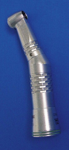
These handpieces impart a mechanical action to the root canal instrument to cut dentine. An early example is the Giromatic, a mechanized handpiece in which the continuous rotation of the driveshaft is transformed into an alternating quarter-turn movement of the file. A later example is the M4 Safety handpiece (SybronEndo, Orange, CA, USA) (Fig. 6.15). This handpiece has a push button-type chuck mechanism to accommodate plastic handled root canal instruments. The handpiece imparts a watch-winding oscillatory movement to the attached root canal instrument.
 |
| Figure 6.15
The SybronEndo M4 Safety handpiece.
|
Rotary NiTi instruments
With the advent of instruments made from NiTi, the endodontic market has become dominated by many new rotary root canal instrument systems (Table 6.2); many consist of a combination of rotary and hand NiTi files. It is impossible to detail all the different rotary NiTi systems but many newer and unique design features have been incorporated by manufacturers.
| ProFile (Dentsply Maillefer, Ballaigues, Switzerland) |
| System GT (Dentsply Maillefer) |
| Quantec (SybronEndo, Orange, CA, USA) |
| Lightspeed LSX (Discus Dental, Culver City, CA, USA) |
| Hero 642 (Micro-Mega, Besançon, France) |
| K3 (SybronEndo) |
| RaCe and BioRaCe (FKG Dentaire, La Chaux-de-Fonds, Switzerland) |
| ProTaper Universal (Dentsply Maillefer) |
| Twisted Files (SybronEndo) |
Variable taper
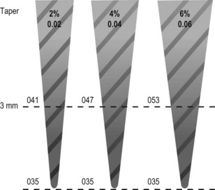
The concept of taper variation is to maximize the cutting efficiency by minimizing the contact area between the surface of the instrument and the canal wall. Instead of having to flare a canal using different sizes of standard 0.02 taper files to achieve the desired shape, the preparation is produced by using files of the desired taper straightaway. The larger the taper, the more conical the shape of the instrument (Fig. 6.16). For ease of use, many rotary instrument systems have matching variable taper hand files, paper points and gutta-percha points.
 |
| Figure 6.16
Taper of root canal instruments.
|
Flute design
The shape of the flutes in cross-section determines cutting efficiency and the ability to remove debris. A design incorporating a reservoir for the dentine debris will help effective evacuation as the debris is transported coronally.
Rake angle
The rake or cutting angle of most conventional instruments is negative so the cutting blade scrapes rather than cuts the dentine, and this is inefficient. A positive rake angle results in more effective cutting but if the rake angle is excessively positive, the cutting blade will dig into the dentine substrate. Therefore, the rake angle should be only slightly positive.
Helical flute angle
This is the angle at which the cutting flutes spiral around the shaft of the instrument. If there are too few spirals, the dentine debris will accumulate quickly before being removed, and the instrument will become clogged. On the other hand, if there are too many spirals, the dentine debris has too great a distance to travel before being evacuated and frictional resistance may trap and compress the debris. The ideal helical flute angle allows efficient removal of dentinal debris without clogging the instrument. Also, increasing the helical flute angle along the length of the file, from tip to handle, assists in debris removal.
Core diameter/flute depth
The core strength and flexibility of an instrument is dependent on its core cross-sectional diameter; the larger the core diameter, the more robust and rigid the instrument. The core diameter is inversely related to the flute depth. The proportion of the core diameter to the outside diameter should be greatest at the tip, where strength is most important. By uniformly decreasing this proportion as the fluting moves up the taper, resulting in greater flute depth, the flexibility increases while the strength of the instrument is maintained. An additional advantage is that dentine debris is also removed more efficiently.
Stay updated, free dental videos. Join our Telegram channel
VIDEdental - Online dental courses


