Quadhelix
This appliance, devised by Ricketts, consists of a palatal arch, shaped like a W, in which four helical loops are incorporated to increase its inherent flexible power.
Laboratory steps
For use in the primary dentition, we prefer to make the quadhelix with 0.032 blue Elgiloy wire; for the mixed and permanent dentitions, we use 0.036 wire. The quadhelix can be either removable or soldered. The construction of a removable quadhelix is shown in Fig 6-1.
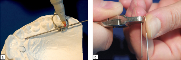
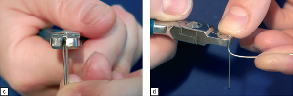
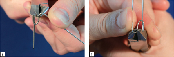
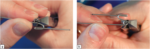
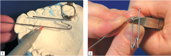
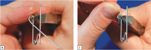
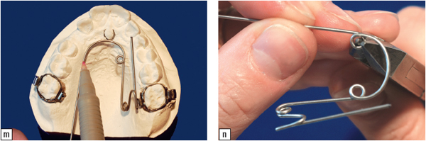
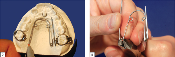
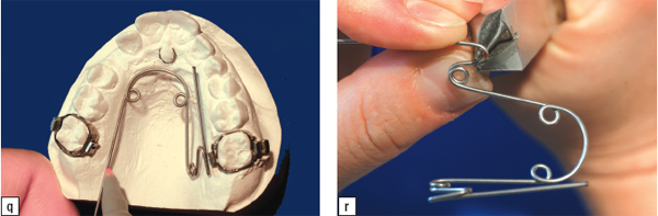
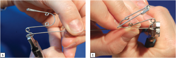
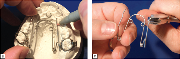
Fig 6-1 Steps in the construction technique of a removable quadhelix.
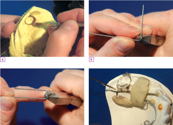
For the soldered quadhelix, a clinical try-in stage is required. The orthodontist takes an alginate impression with the uncemented first molar bands in place in the mouth. The operator removes the bands and sets them carefully into the impression, which is then poured after a little sticky wax has been dropped inside the bands to secure them (Fig 6-2a). The technician constructs and adjusts the quadhelix and solders it to the bands on the working cast (Figs 6-2b to 6-2d).
Activation
There are two ways to activate the quadhelix before placing it in the mouth. Ricketts et al (1979) originally suggested that operators activate the appliance with a three-pronged pliers to incorporate expansion and molar-rotating force (Fig 6-3). The authors use another method proposed by Kholoki (1995). It employs an arch form chosen from a pentamorphic chart that serves as a pattern for regulating the quadhelix (Figs 6-4 to 6-7).
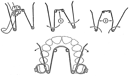
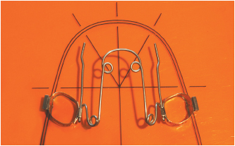
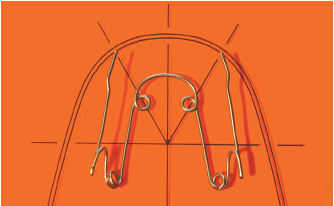
Fig 6-4b To activate a removable quadhelix, place the molar segments parallel to the palatal midl ine 8 to 10 mm inside the pattern, a distance that corresponds to the average buccopalatal diameter of a maxillary first molar. With this maneuver, the device will have the capability to correct molar rotation and accomplish expansion in conformity with the requirements of the specific arch form.
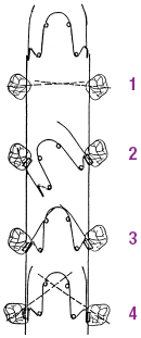
Fig 6-5 Schematic representation of the effects of parallelism on the buccal segments horizontally: (1) When the molars are rotated mesially, the quadhelix is activated in conformity to arch form. The molar segments of the device are parallel to the palatal midline (toe-in information). (2)When one of the two molar segments of the quadhelix is inserted in the palatal molar tube, the contralateral segment will lie distal to its molar. (3) With the two molar segments now set in the tubes, the appliance exerts rotational force on the molars. (4) The mesial rotation of the molars has been corrected.
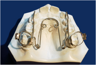
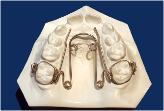
Fig 6-6b Quadhelix in place on the cast.
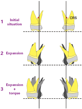
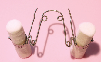
Fig 6-7b Method for assessing the preactivated torque. Place a cotton roll in each molar band and see if the protruding parts are parallel, which would indicate that the torque force is zero. If they diverge, pointing up and outward, the torque is acting buccally. This information must be incorporated in the appliance if it is to act orthopedically. Torque force is imparted to the soldered part of the band for the cemented quadhelix and to the molar segment that is inserted in the palatal tubes for the removable quadhelix; the wire, being bent on itself, functions like a rectangular arch.
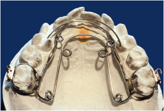
Crozat quadhelix
Construction of a Crozat quadhelix is shown in Fig 6-8.
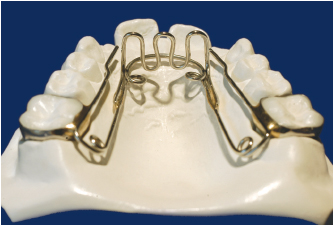
Quadhelix with lingual spurs
Lingual spurs can be soldered to the quadhelix (Fig 6-9).
Bihelix
Laboratory steps
The alginate impression is poured with the tried-in molar bands set in place. This should be a good, deep impression that accurately reproduces the lingual area and the lingual frenum. The appliance is constructed in blue Elgiloy 0.036 wire in the same way as a soldered quad-helix without anterior loops.
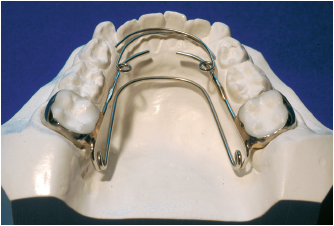
Crozat bihelix
The Crozat bihelix (Fig 6-10) is distinguished from a simple bihelix by the anterior springs soldered to the lateral arms that are used to move the mandibular incisors labially.
1. Distolingual rotation of maxillary molars so that they can occlude correctly with their mandibular counterparts
2. Recontouring of the mandibular alveolar shelf to provide increased arch length
3. Expansion of the anterior region to create space for labial movement of the incisors
4. Molar anchorage
5. Space maintenance
Activation
Stay updated, free dental videos. Join our Telegram channel
VIDEdental - Online dental courses


