Fundamentals of Materials Science
Restorative dental materials are subjected to a very hostile environment, in which pH, salivary flow, and mechanical loading fluctuate constantly and often rapidly. These challenges have required substantial research and development to provide products for the clinician. Much of this is possible through the application of fundamental concepts of materials science. The understanding of properties of polymers, ceramics, and metals is crucial to their selection and design of dental restorations.
No single property defines the quality of a material. Often several properties, determined from standardized laboratory and clinical tests, are used to describe quality. Laboratory tests, although they are only surrogates for clinical studies, provide standardized measures for comparing materials and guiding the interpretation of clinical trials.
Standardization of laboratory tests is essential, however, to control quality and permit comparison of results between investigators. When possible, test specimens should mimic the size and shape of the structure in the clinical setting, with mixing and manipulating procedures being equivalent to routine clinical conditions.
Although it is important to know the comparative values of properties of different restorative materials, it is also essential to know the quality of the supporting and investing hard and soft tissues. Many restorations fail clinically because of fracture or deformation. This is a material property issue. Some well-constructed restorations become unserviceable because the supporting tissue fails. This is an interface or substrate failure. Consequently, when designing restorations and interpreting test results, it is important to remember that the success of a restoration depends not only on its physical qualities but also on the biophysical or physiological qualities of the supporting tissues.
The physical properties described in this chapter include mechanical properties, thermal properties, electrical and electromechanical properties, color, and optical properties.
Mechanical Properties
In the oral environment, restorative materials are exposed to chemical, thermal, and mechanical challenges. These challenges can cause deformation of the material. The science that studies how biological materials interact and deform is called biomechanics. This section introduces concepts of elastic, plastic, and viscoelastic deformation and mechanical quantities including force, stress, strain, strength, toughness, hardness, friction, and wear in terms of performance of materials in the oral environment.
Force
One body interacting with another generates force. Forces may be applied through actual contact of the bodies or at a distance (e.g., gravity). The result of an applied force on a body is translation or deformation of the body depending on whether the body is rigid or deformable and whether the body is constrained. If the body is constrained (i.e., does not move or translate), the force causes the body to deform or change its shape. If the body is free of constraints, an applied force results in movement or translation.
A force is defined by three characteristics: point of application, magnitude, and direction of application. The direction of a force is characteristic of the type of force. The International System of Units (SI) unit of force is the Newton (N). One pound-force (lb-f) equals 4.4 Newtons (N).
Occlusal Forces
Maximum occlusal forces range from 200 to 3500 N. Occlusal forces between adult teeth are highest in the posterior region closest to the mandibular hinge axis and decrease from the molar region to the incisors. Forces on the first and second molars vary from 400 to 800 N. The average force on the bicuspids, cuspids, and incisors is about 300, 200, and 150 N, respectively. A somewhat nonlinear but definite increase in force from 235 to 494 N occurs in growing children, with an average yearly increase of about 22 N.
Forces on Restorations
Occlusal forces with dental prosthetic devices are generally lower than with natural dentition. Patients with removable partial dentures generate occlusal forces in the range of 65 to 235 N. For patients with complete dentures, the average force on the molars and bicuspids is about 100 N; the forces on the incisors averages 40 N. Age and gender variations in the patient populations contribute to the large variation in force values. In general, the occlusal force produced by women is about 90 N less than that applied by men. Facial form and muscle definition are good predictors of occlusal force capacity. Patients with high mandibular angles generally exhibit lower occlusal forces than patients with low angles and square mandibular form.
Maximum occlusal force and the response of underlying tissues change with anatomic location, age, occlusal scheme, and placement of a dental prosthesis. When designing restorations and selecting materials, it is important to consider the location, opposing dentition, and force-generating capacity of the patient. These factors can often be estimated by the success or failure of other restorations in the patient’s mouth. A material or design sufficient to withstand the forces of occlusion in the anterior segment may not be sufficient for the posterior segment.
Stress
When a force acts on a constrained body, the force is resisted by the body. This internal reaction is equal in magnitude and opposite in direction to the applied external force, and is called stress, typically denoted as S or σ. Both the applied force and the internal resistance (stress) are distributed over an area of the body, so the stress in an object is defined as the force per area, or stress = force/area. Stress is difficult to measure directly, so the force and the area to which the force is applied are measured, and stress is calculated from the ratio of force per area. The unit of stress therefore is the unit of force (N) divided by a unit of area, and is commonly expressed in SI units as Pascal (1 Pa = 1 N/m2 = 1 MN/mm2). It is common to report stress in units of megaPascals (MPa) or millions of Pascals, 1 MPa = 106 Pa.
Because the stress in a structure varies directly with the force and inversely with area, the area over which the force acts is an important consideration. This is particularly true in dental restorations in which the areas over which the forces are applied often are extremely small. For example, cusp areas of contact may have cross-sectional areas of only 0.16 to 0.016 cm2.
As a numerical example, a 20-gauge orthodontic wire has a diameter of 0.8 mm and a cross-sectional area of 0.5 mm2. If a 220-N force is applied to a wire of this diameter, the stress developed is equivalent to 220 N/0.5 mm2, or 440 N/mm2 (MPa).
Stress is always normalized to a 1 m2 area, but a dental restoration such as a small occlusal pit restoration may have no more than 4 mm2 of surface area, if the restoration is 2 mm on a side. If an occlusal force of 440 N is concentrated on this area, the stress developed would be 100 MPa. Therefore, stresses equivalent to several hundred MPa occur in many types of restorations. Stresses can be produced in the range of thousands of MPa when the contact area of a cusp or dental explorer is used to apply the force. This is one reason that premature contacts, in which small surface areas are supporting large occlusal forces, are so damaging. When equilibrating the occlusion, multiple simultaneous occlusal contacts are desirable. Distributing occlusal forces over larger surface areas reduces the local occlusal stress.
Types of Stress
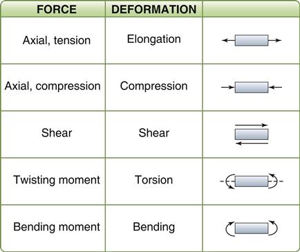
A force can be applied from any angle or direction, and often several forces combine to develop complex stresses in a structure. It is rare for forces and stresses to be isolated to a single axis. Individually applied forces can be defined as axial, shear, bending, or torsional. These directional forces are illustrated in a simplified manner in Figure 4-1. All stresses, however, can be resolved into combinations of two basic types—axial and shear.
Tension results from two sets of forces directed away from each other in the same straight line or when one end is constrained and the other end is subjected to a force directed away from the constraint. Compression results from two sets of forces directed toward each other in the same straight line or when one surface is constrained and the other is subjected to a force directed toward the constraint. Shear occurs from two sets of forces directed parallel to each other, but not along the same straight line. Torsion results from the twisting of a body, and bending or flexure results from an applied bending moment. When tension is applied, the molecules making up the body resist being pulled apart. When compression is applied, they resist being forced more closely together. As a result of a shear stress application, one portion of the body must resist sliding past another. These resistances of a material to deformation represent the basic qualities of elasticity of solid bodies.
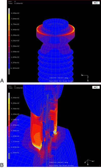
An example of the complexity and varying direction and magnitude of stresses in the oral cavity is shown in Figure 4-2, in which a finite element model of a dental implant is loaded in compression. Figure 4-2, A, shows the stresses on the shoulder of the implant resulting from occlusal forces. Figure 4-2, B, shows the distribution of stresses in the implant abutment.
Strain
Each type of stress is capable of producing a corresponding deformation in a body (see Figure 4-1). The deformation from a tensile force is an elongation in the axis of applied force, whereas a compressive force causes compression or shortening of the body in the axis of loading. Strain, ε, is described as the change in length (ΔL = L − Lo) per original length (Lo) of the body when it is subjected to a load. The units of measurement (length/length) cancel in the calculation of strain.
< ?xml:namespace prefix = "mml" ns = "http://www.w3.org/1998/Math/MathML" />

If a load is applied to a wire with an original length of 2 mm resulting in a new length of 2.02 mm, it has deformed 0.02 mm and the strain is 0.02/2 = 0.01, or 1%. Strain is often reported as a percentage. Although the length units cancel in the calculation of strain, it is best to report the units with the final result to specify the scale of the measurement (m/m; mm/mm; μm/μm). The amount of strain will differ with each type of material and with the magnitude of the load applied. Note that regardless of the composition or nature of the material, and regardless of the magnitude and type of load applied to the material, deformation and strain result with each stress application. Strain is an important consideration in dental restorative materials, such as orthodontic wires or implant screws, in which a large amount of strain can occur before failure. Wires can be bent and adjusted without fracturing. Strain is also important in impression materials, where the material needs to recover without permanent distortion when removing it from hard tissue undercuts.
Stress-Strain Curves
If a bar of material is subjected to an applied force, F, the magnitude of the force and the resulting deformation (δ) can be measured. In another bar of the same material, but different dimensions, the same applied force produces different force-deformation characteristics (Figure 4-3, A). However, if the applied force is normalized by the cross-sectional area A of the bar (stress), and the deformation is normalized by the original length of the bar (strain), the resulting stress-strain curve is independent of the geometry of the bar (Figure 4-3, B). It is therefore preferred that the stress-strain relations of an object be reported rather than the force-deformation characteristics. The stress-strain relationship of a dental material can be studied by measuring the load and deformation and then calculating the corresponding stress and strain.
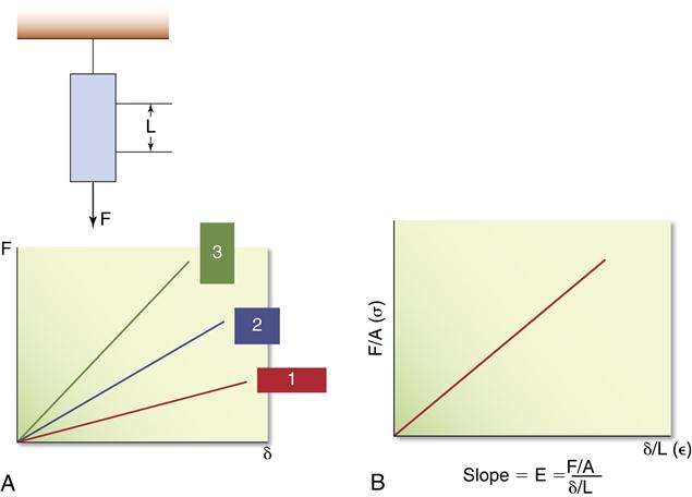
A, Force-deformation characteristics for the same material but having different dimensions. B, Stress-strain characteristics of the same group of bars. The stress-strain curve is independent of the geometry of the bar.
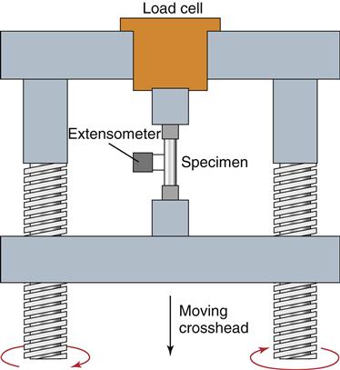
When testing materials, loads should be applied at a uniform rate, and deformation should occur at a uniform rate. A typical universal testing machine can analyze materials in tension, compression, or shear. In the scheme illustrated in Figure 4-4, a rod is clamped between two jaws and a tensile force is applied. The load is measured with a force transducer and the deformation is measured with an extensometer clamped over a specified length of the specimen. A plot of load versus deformation is produced, which can be converted to a plot of stress versus strain (Figure 4-5) by the simple calculations described previously. By convention, strain is plotted on the x-axis as an independent variable because most tests are operated in strain control, where a constant strain is applied to the specimen and the resulting force is measured as the dependent, or y-axis, variable.
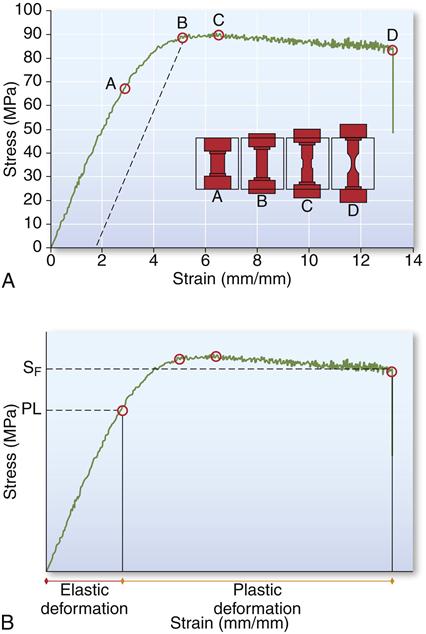
A, Stress-strain curve for a material subjected to tensile stress. Specimens illustrate amount of deformation at each point (A-D). B, Elastic deformation is exhibited up to the proportional limit (PL) and plastic deformation is exhibited from PL to the failure point (FP).
In the calculation of stress, it is assumed that the cross-sectional area of the specimen remains constant during the test. Using this assumption, the stress-strain curve is called an engineering stress-strain curve, and stresses are calculated using the original cross-sectional area. When large loads are applied, or the object is tested in tension, the cross-sectional area might change dramatically during testing. In that case, the true stress, calculated with the actual cross-sectional area in the denominator, is very different than the engineering stress, calculated with the original cross-sectional area. If the cross-sectional area decreases during the test, the true stress will be higher than the engineering stress because the denominator is smaller. In most mechanical tests, particularly those of small specimen dimensions, the original cross-sectional area is used for calculating stress because it is often very difficult to measure the cross-sectional area as it changes throughout the experiment. Engineering stress is used in the presentation of stress-strain curves obtained in tension in this chapter.
Proportional and Elastic Limits
A stress-strain curve for a hypothetical material subjected to increasing tensile stress until failure is shown in Figure 4-5. As the stress is increased, the strain is increased. In the initial portion of the curve, from 0 to A, the stress is linearly proportional to the strain. As the strain is doubled, the stress is also doubled. After point A, the stress is no longer linearly proportional to the strain. Hence the value of the stress at A is known as the proportional limit (SPL or σPL), defined as the highest stress at which the stress-strain curve is a straight line, that is, stress is linearly proportional to strain. Below the proportional limit, no permanent deformation occurs in a structure. When the force is removed, the object will return to its original dimensions. Below the proportional limit, the material is elastic in nature.
The region of the stress-strain curve before the proportional limit is called the elastic region. When an object experiences a stress greater than the proportional limit, permanent or irreversible strain occurs. The region of the stress-strain curve beyond the proportional limit is called the plastic region. This characterization refers to linearly elastic materials such as many metals in which the relation between stress and strain is linear up to the proportional limit, and nonlinear thereafter. There are exceptions to this general rule, however. Materials described as superelastic exhibit nonlinear elastic behavior; that is, their relationship between stress and strain in the elastic region does not follow a straight line, but removal of the load results in a return to zero strain.
The elastic limit (SEL or σEL) is defined as the maximum stress that a material will withstand without permanent deformation. For linearly elastic materials, the proportional limit and elastic limit represent the same stress within the structure, and the terms are often used interchangeably in referring to the stress involved. An exception is when superelastic materials are considered. It is important to remember, however, that the two terms differ in fundamental concept; one deals with the proportionality of strain to stress in the structure, whereas the other describes the elastic behavior of the material. For the same material, values for proportional or elastic limit obtained in tension versus compression will differ.
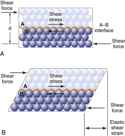
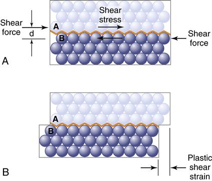
The concepts of elastic and plastic behavior can be illustrated with a simple schematic model of the deformation of atoms in a solid under stress (Figures 4-6 and 4-7). The atoms are shown in Figure 4-6, A, without stress, and in Figure 4-6, B, with a resulting stress that is below the value of the proportional limit. When the stress shown in B is removed, the atoms return to their positions shown in A, indicating that the deformation was reversible. When the stress is greater than the proportional limit, the atoms move to a position as shown in Figure 4-7, B, and on removal of the stress, the atoms remain in this new position, indicating an irreversible, permanent deformation. When the stress is less than the proportional or elastic limit, the strain is reversible, whereas when the stress is greater than the proportional or elastic limit, there is an irreversible or permanent strain in the object.
Yield Strength
It is often difficult to explicitly measure the proportional and elastic limits because the precise point of deviation of the stress-strain curve from linearity is difficult to determine. The yield strength or yield stress or yield point (YS or σY) of a material is a property that can be determined readily and is often used to describe the stress at which the material begins to function in a plastic manner. At this point, a small, defined amount of permanent strain has occurred in the material. The yield strength is defined as the stress at which a material deforms plastically and there is a defined amount of permanent strain. The amount of permanent strain is arbitrarily selected for the material being examined and may be indicated as 0.1%, 0.2%, or 0.5% (0.001, 0.002, 0.005) permanent strain. The amount of permanent strain is referred to as the percent offset. Many specifications use 0.2% as a convention, but this depends on the plastic behavior of the material tested. For stiff materials with small elongation, the calculation of yield stress will include greater offsets than those materials with larger elongation or deformation.
The yield stress is determined by selecting the desired offset or strain on the x-axis and drawing a line parallel to the linear region of the stress-strain curve. The point at which the parallel line intersects the stress-strain curve is the yield stress. On the stress-strain curve shown in Figure 4-5, for example, the yield strength is represented by the value B. This represents a stress of about 360 MPa at a 0.25% offset. This yield stress is slightly higher than that for the proportional limit because it includes a specified amount of permanent deformation. Note that when a structure is permanently deformed, even to a small degree (such as the amount of deformation at the yield strength), it does not return completely to its original dimensions when the stress is removed. For this reason, the elastic limit and yield strength of a material are among its most important properties because they define the transition from elastic to plastic behavior.
Any dental restoration that is permanently deformed through the forces of mastication is usually a functional failure to some degree. For example, a fixed partial denture that is permanently deformed by excessive occlusal forces would exhibit altered occlusal contacts. The restoration is permanently deformed because a stress equal to or greater than the yield strength was generated. Recall also that malocclusion changes the stresses placed on a restoration; a deformed restoration may therefore be subjected to greater stresses than originally intended because the occlusion that was distributed over a larger number of occlusal contacts may now be concentrated on a smaller number of contacts. Under these conditions, fracture does not occur if the material is able to plastically deform. Permanent deformation results, which represents a destructive example of deformation. Permanent deformation and stresses in excess of the elastic limit are desirable when shaping an orthodontic arch wire or adjusting a clasp on a removable partial denture. In these examples, the stress must exceed the yield strength to permanently bend or adapt the wire or clasp. Elastic deformation occurs as the wire or clasp engages and disengages a retentive undercut in the cervical area of the tooth. Retention is achieved through small-scale elastic deformation. This elastic or reversible deformation describes the function of elastic bands, clasps, o-rings, and implant screws.
Ultimate Strength
In Figure 4-5, the test specimen exhibits a maximum stress at point C. The ultimate tensile strength or stress (UTS) is defined as the maximum stress that a material can withstand before failure in tension, whereas the ultimate compressive strength or stress (UCS) is the maximum stress a material can withstand in compression. The ultimate engineering stress is determined by dividing the maximum load in tension (or compression) by the original cross-sectional area of the test specimen. The ultimate tensile strength of the material in Figure 4-5 is about 380 MPa.
The ultimate strength of an alloy as used in dentistry specifies the maximum load and minimum cross-sectional area when designing a restoration. Note that an alloy that has been stressed to near the ultimate strength will be permanently deformed, so a restoration receiving that amount of stress during function would be useless. A safety margin should be incorporated into the design of the restoration and choice of material to ensure that the ultimate strength is not approached in normal function. The yield strength is often of greater importance than ultimate strength in design and material selection because it is an estimate of when a material will start to deform permanently.
Fracture Strength
In Figure 4-5 the test specimen fractured at point D. The stress at which a brittle material fractures is called the fracture strength or fracture stress (SF or σF). Note that a material does not necessarily fracture at the point at which the maximum stress occurs. After a maximum tensile force is applied to some materials, the specimen begins to elongate excessively, resulting in “necking” or a reduction of cross-sectional area (see Figure 4-5). The stress calculated from the force and the original cross-sectional area may drop before final fracture occurs because of the reduction in cross-sectional area. Accordingly, the stress at the end of the curve is less than at some intermediate point on the curve. Therefore, in materials that exhibit necking, the ultimate and fracture strengths are different. However, for the specific cases of many dental alloys and ceramics subjected to tension, the ultimate and fracture strengths are similar, as is shown later in this chapter. Note that the reduction in stress that is observed after the ultimate stress in materials that show necking is an artifact of using the original cross-sectional area in the calculation of stress. If the true cross-sectional area is used, the stress would increase.
Elongation
The deformation that results from the application of a tensile force is elongation. Elongation />
Stay updated, free dental videos. Join our Telegram channel

VIDEdental - Online dental courses


