Testing of Dental Materials and Biomechanics
In Chapter 4, we introduced fundamental concepts in biomechanics and physical properties of dental materials. The data presented were collected with a variety of test instruments. In this chapter we describe the individual tests in more detail.
Compressive Strength
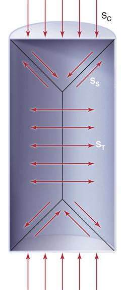
When an object is tested in compression, failure might occur as a result of complex stresses in the object. The forces of compression applied to each end of the specimen are resolved into forces of shear along a cone-shaped area at each end and, as a result of the action of the two cones on the cylinder, into tensile forces in the central portion of the mass. Because of this resolution of forces in the body, it has become necessary to adopt standard sizes and dimensions to obtain reproducible test results. Figure 5-1 shows that if a test specimen is too short, the force distributions become more complicated as a result of the cone formations overlapping in the ends of the cylinder. If the specimen is too long, buckling may occur. Therefore, the cylinder should have a length twice that of the diameter for the most satisfactory results.
Compressive strength is most useful for comparing materials that are brittle and generally weak in tension. Compressive strength is therefore a useful property for the comparison of dental amalgam, resin composites, and cements and for determining the qualities of other materials such as plaster and investments. Typical values of compressive strength of some restorative dental materials are given in Table 5-1.
TABLE 5.1
Compressive Strength of Selected Dental Materials
| Material | Compressive Strength (MPa) |
| Enamel | 384 |
| Dentin | 297 |
| Amalgam | 189 |
| Calcium hydroxide liner | 8 |
| Feldspathic porcelain | 149 |
| High-strength stone | 81 |
| Resin composite | 225 |
| Zinc phosphate cement | 110 |
Flexure
The bending, or flexural, properties of many materials are often more important than their tensile or compressive properties. The flexural properties of stainless steel wires, endodontic files and reamers, and hypodermic needles are especially important. For example, American National Standards Institute/American Dental Association (ANSI/ADA) specification No. 28 for endodontic files and reamers requires flexure tests.
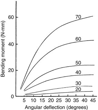
Flexural properties are measured by bending a beam-shaped specimen. In a single cantilever beam configuration, the beam is fixed at one end and a force is applied at a prescribed distance from the fixed end. In a dual cantilever beam configuration, both ends of the beam are fixed and a load is placed on the center of the beam. In a three-point or four-point flexural configuration, the beam is supported on two rollers and a load is applied to the top of the beam. Specimens are subjected to conditions that resemble pure bending, and beam theory is used to analyze the data. As the force is increased and the specimen is bent, corresponding values for the angle of bending and the bending moment (force × distance) are recorded. Graphic plots of the bending moment versus the angle of bending are similar in appearance to stress-strain curves. As an example, a series of plots for various sizes of endodontic reamers is shown in Figure 5-2. An instrument will be permanently bent if the bending angle exceeds the value at the end of the linear portion of the curve. The larger instruments are stiffer, as shown by the initial steeper slope. The initial linear portion of the curve is shorter for the larger instruments and thus the deviation from linearity occurred at lower angular bends.
Flexural Strength
The flexural strength of a material is obtained when one loads a simple single beam, simply supported (not fixed) at each end, with a load applied in the middle (Figures 5-3 and 5-4). Such a test is called a three-point bending (3PB) or flexure test and the maximum stress measured in the test is called flexural strength. The flexural strengths for several dental materials are shown in Table 5-2. This test determines not only the strength of the material indicated but also the amount of distortion expected. The flexural strength test is a part of ANSI/ADA specification No. 12 (ISO 1567) for denture base resins. The flexural strength and accompanying deformation are important also in long fixed partial denture spans in which the occlusal stress may be severe.
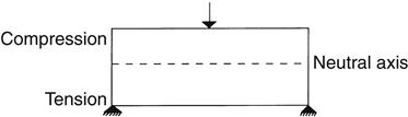
The three points are the two supports at the bottom and the central loading point on the top.
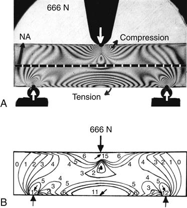
A, Photo-elastic model with isochromatic fringes. B, Drawing to illustrate isochromatic fringe order. Neutral axis (NA).
TABLE 5.2
Flexural Strength of Selected Dental Materials
| Material | Flexural Strength (MPa) |
| Resin composite | 139 |
| Lathe-cut amalgam | 124 |
| Feldspathic porcelain | 65 |
| High-strength stone | 17 |
| Resin-modified glass ionomer | 42-68 |
| Resin cement | 66-121 |
The equation for the maximum stress developed in a rectangular beam loaded in the center of the span is as follows:
< ?xml:namespace prefix = "mml" ns = "http://www.w3.org/1998/Math/MathML" />

or

The resulting deformation or displacement in such a beam or bridge can be calculated from the following equation:

or

Four-point bending is often preferred to three-point bending when measuring flexural modulus and flexural strength. If an easily deformed material is tested with inadequately rounded loading and support elements, the elements can cause localized deformation. This is undesirable because the beam theory used to calculate deflection assumes uniform beam deformation without localized stresses and constraints. A four-point bend fixture uses two loading elements instead of the one used in a three-point bend fixture. The two loading elements apply a more uniform load to the beam that prevents V-shaped buckling of the beam, and stress concentrations in the midline when a single loading element is used. In this configuration, a larger, more representative area of the specimen is tested.
Permanent Bending
During fabrication, many dental restorations are subjected to permanent bending. The adjustment of removable partial denture clasps and the shaping of orthodontic wires are two examples of such bending operations. Comparisons of wires and needles of different compositions and diameters subjected to repeated 90-degree bends are often made. The number of bends a specimen will withstand is influenced by its composition and dimensions, as well as its treatment in fabrication. Such tests are important because this information is not readily related to standard mechanical test data such as tensile properties or hardness. Severe tensile and compressive stresses can be introduced into a material subjected to permanent bending. It is partly for this reason that tensile and compressive test data for a material are so important.
Diametral Tensile Strength
An alternative method of testing brittle materials, in which the ultimate tensile strength of a brittle material is determined through compressive testing, is popular because of its relative simplicity and reproducibility. The method is described in the literature as the diametral compression test for tension or the Brazilian method. In this test, a disk of the brittle material is compressed diametrically in a testing machine until fracture occurs, as shown in Figure 5-5. The compressive stress applied to the specimen introduces a tensile stress in the material in the plane of the force application of the test machine because of the Poisson effect. The tensile stress (σx) is directly proportional to the load (P) applied in compression through the following formula:

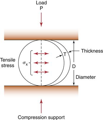
Note that this test is designed for brittle materials. If the specimen deforms significantly before failure or fractures into more than two equal pieces, the data may not be valid. Some materials exhibit different diametral tensile strengths when tested at different rates of loading and are described as being strain-rate sensitive. The diametral tensile test is not valid for these materials. Values of diametral and ultimate tensile strengths for some dental materials are listed in Table 5-3.
TABLE 5.3
Tensile Strength of Selected Dental Materials
| Material | Diametral Tensile Strength (MPa) | Ultimate Tensile Strength (MPa) |
| Enamel | — | 10 |
| Dentin | — | 106 |
| Amalgam | 54 | 32 |
| Calcium hydroxide liner | 1 | 2.3 |
| Feldspathic porcelain | — | 25 |
| High-strength stone | 8 | 6 |
| Zinc phosphate cement | 8 | 10 |
Shear Strength
The shear strength is the maximum stress that a material can withstand before failure in a shear mode of loading. It is particularly important in the study of interfaces between two materials, such as ceramic-metal or an implant-bone interface. One method of testing the shear strength of dental materials is the punch or push-out method, in which an axial load is applied to push one material through another. The shear strength (τ) is calculated by the following formula:

where F is the compressive force applied to the specimen, d is the diameter of the punch, and h is the thickness of the specimen. Note that the stress distribution caused by this method is not pure shear and that results often differ because of differences in specimen dimensions, surface geometry, composition and preparation, and mechanical testing procedure. However, it is a simple test to perform and has been used extensively. Alternatively, shear properties may be determined by subjecting a specimen to torsional loading. Shear strengths of some dental materials are listed in Table 5-4. The specifics of shear testing for adhesive interfaces is discussed in detail in the bond strength methods section of this chapter.
TABLE 5.4
Values of Shear Strength Tested by the Punch Method for Some Restorative Dental Materials
| Material | Shear Strength (MPa) |
| Enamel | 90 |
| Dentin | 138 |
| Acrylic denture resin | 122 |
| Amalgam | 188 |
| Porcelain | 111 |
| Zinc phosphate cement | 13 |
Torsion
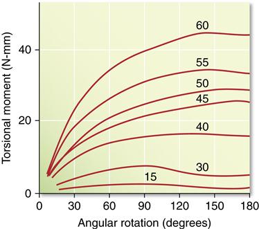
Another mode of loading important to dentistry is torsion or twisting. For example, when an endodontic file is clamped at the tip and the handle is rotated, the instrument is subjected to torsion. Because most endodontic files and reamers are rotated in the root canal during endodontic treatment, their properties in torsion are of particular interest. ANSI/ADA specification No. 28 for endodontic files and reamers describes a test to measure resistance to fracture by twisting with a torque meter. Torsion results in a shear stress and a rotation of the specimen. In these types of applications, we are interested in the relation between torsional moment (Mt = shear force × distance) and angular rotation π. A series of graphs in which the torsional moment was measured as a function of angular rotation are shown in Figure 5-6. In this example, the instruments were twisted clockwise, which results in an untwisting of the instrument. As was the case with bending, the curves appear similar to stress-strain curves, with an initial linear portion followed by a nonlinear portion. The instruments should be used clinically so that they are not subjected to permanent angular rotation; thus the degrees of rotation should be limited to values within the linear portion of the torsional moment–angular rotation curves. The larger instruments are stiffer in torsion than the smaller ones, but their linear portion is less. The irregular shape of the curves at high angular rotation results from the untwisting of the instruments. Torsion is also an important consideration for threaded fasteners such as those used in implant restorations. Use of a torque gage is recommended for tightening abutment screws to prevent overloading the screw and possible torsional failure in the shank of the screw.
Fatigue Strength
Based on the previous discussions, an object that is subjected to a stress below the yield stress and subsequently relieved of this stress should return to its original form without any change in its internal structure or properties. A few cycles of loading and unloading do not appreciably affect a material. However, when this stress is repeated many times, the strength of the material may be drastically reduced and ultimately cause failure. Fatigue is defined as a progressive fracture under repeated loading. Fatigue tests are performed by subjecting a specimen to alternating stress applications below the yield strength until fracture occurs. Tensile, compressive, shear, bending, and torsional fatigue tests can all be performed.
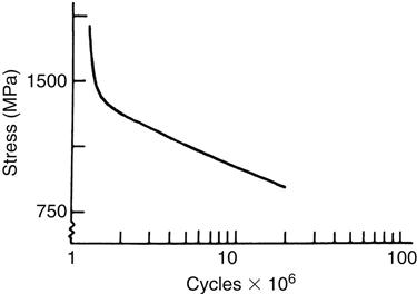
The fatigue strength is the stress level at which a material fails under repeated loading. Failure under repeated or cyclic loading is therefore dependent on the magnitude of the load and the number of loading repetitions. Fatigue data are often represented by an S-N curve, a curve depicting the stress (or strain) (S) at which a material will fail as a function of the number of loading cycles (N). An example of an S-N curve is shown in Figure 5-7. When the stress is sufficiently high, the specimen will fracture at a relatively low number of cycles. As the stress is reduced, the number of cycles required to cause failure increases. Therefore, when specifying fatigue strength, the number of cycles must also be specified. For some materials, a stress at which the specimen can be loaded an infinite number of times without failing is eventually approached. This stress is called the endurance limit.
The determination of fatigue properties is of considerable importance for dental restorations subjected to cyclic forces during mastication. Stress applications during mastication may approach 300,000 flexures per year. Because dental materials can be subjected to moderate stresses repeated a large number of times, it is important in the design of a restoration to know what stress it can withstand for a predetermined number of cycles. Restorations should be designed with a safety margin so the clinical cyclic stresses are below the fatigue limit.
Fatigue fractures develop from small cracks that coalesce and ultimately lead to a macroscopic crack and catastrophic failure. Areas of stress concentration, such as surface defects and notches, are particularly dangerous and can lead to catastrophic failure. Fatigue properties are mostly dependent on the microstructure of the material, and the history of fabrication and treatment; therefore, they do not always directly correlate to other mechanical properties. Also, the environment plays a role, because the medium in which the material is submersed when in use may also cause degradation. Elevated temperatures, humidity, aqueous media, biological substances, and pH deviations away from neutral can all reduce fatigue properties. As a result, fatigue data, which are typically presented based on tests in laboratory air at room temperature, are not always relevant to the service conditions in the oral cavity. The higher temperature, humidity, saline environment with proteins, and fluctuating pH all tend to reduce fatigue strength from its level in the laboratory.
Fracture Toughness
A fracture toughness test is usually performed using flexure bars with a notch, at the tip of which a crack with a nanometer-sized tip is introduced. In this configuration, materials can be characterized by the energy release rate, G, and the stress intensity factor, K. The energy release rate is a function of the energy involved in crack propagation, whereas the stress intensity factor describes the stresses at the tip of a crack. The stress intensity factor changes with crack length and stress according to the following formula:

where Y is a function that is dependent on crack size and geometry. A material fractures when the stress intensity reaches a critical value, Kc. This value of the stress intensity at fracture is called the fracture toughness. Fracture toughness gives a relative value of a material’s ability to resist crack propagation. The units of Kc are units of stress (force/length2) × units of length1⁄2, or force × length−3⁄2, and are typically reported as MN m−3⁄2 or MPa m1⁄2.
Fractographic Analysis
Fractographic analysis has been used in engineering for many years to help define the cause of failures and aid in structural design, as well as to improve existing materials. Its use in dentistry is relatively recent, but advances in the field have helped identify the role of residual stresses, temperature, and preexisting flaws on the longevity of dental restorations.
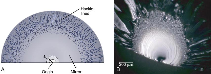
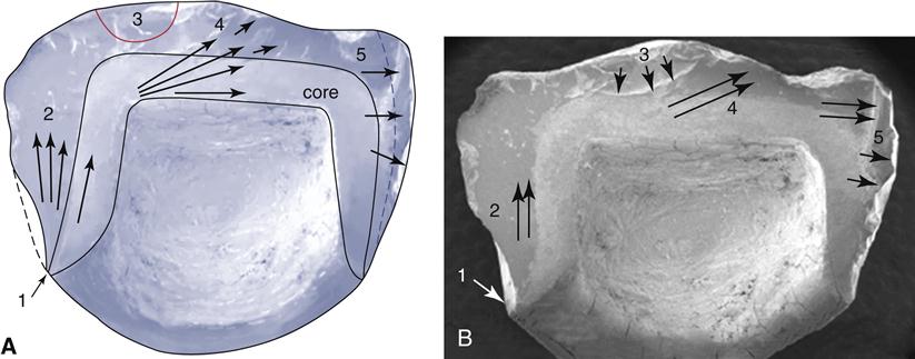
Brittle materials are easier to analyze with fractography because they typically fail catastrophically. The typical features of crack propagation (Figure 5-8) are readily identified and the origin of the fracture can be determined. The origin of fracture is the point at which the worst combination of flaw severity (determined by flaw size and shape) and stress demands are present. Differences in processing of ceramics, for example, may lead to significantly different structures, as shown in Figure 5-9, with a homogenous structure produced by effective processing. Flaw growth is observed from cumulative mistakes during processing. Flaws larger than the ones observed in Figure 5-9, B, are considered critical. In Figure 5-9, D, the problem is maximized by the presence of a very sharp flaw that concentrates stresses.
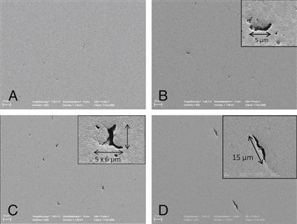
A, Shows a well processed material, with little to no flaws present. The sequence from B through D shows materials with increasingly bigger/sharper flaws, resulting from poor processing. (Courtesy of Scherrer SS, University of Geneva)
In the clinical situation, poor prosthesis design may also lead to failure, even if a preexisting flaw is not present. Fractographic analysis allows the origin to be identified, but in these cases, the fracture patterns are much more complex. In Figure 5-10 chipping caused a catastrophic failure at a margin where the porcelain structure was excessively thin.
Tear Strength and Tear Energy
Tear strength is a measure of the resistance of a material to tearing forces. Tear strength is an important property of dental polymers used in thin sections, such as flexible impression materials in interproximal areas, maxillofacial materials, and soft liners for dentures. Specimens for tear strength testing are usually crescent-shaped and notched. The tear strength of the notched specimen is calculated by dividing the maximum load by the thickness of the specimen. The unit of tear strength is N/m.
Because of the viscoelastic nature of the materials tested, tear strength depends on the rate of loading. Rapid loading rates result in higher values of tear strength. Clinically, the rapid (or snap) removal of an alginate impression is recommended to maximize the tear strength and also to minimize permanent deformation. Typical values of tear strength are listed in Table 5-5 for some dental materials.
TABLE 5.5
Tear Strength of Selected Dental Materials
| Material | Tear Strength (KN/m) |
| Denture liners | 2.6-45 |
| Agar duplicating materials | 0.22 |
| Impression materials | |
| Agar | 1.0 |
| Alginate | 0.47 |
| Polysulfide | 3.6 |
| Polyvinylacetate-polyethylene mouth protectors | 114 |
The tear energy (T) is a measure of the energy per unit area of newly torn surface and is determined from the load (F) required to propagate a tear in a trouser-shaped specimen as follows:

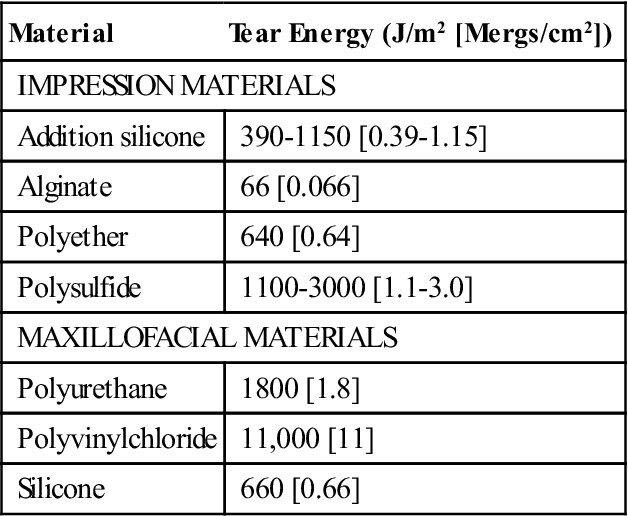
where t is the specimen thickness and λ is an extension ratio. Typical values of tear energy determined for some dental impression materials and maxillofacial materials are listed in Table 5-6.
TABLE 5.6
Tear Energy∗ (T) of Some Dental Materials
< ?comst?>
| Material | Tear Energy (J/m2 [Mergs/cm2]) |
| IMPRESSION MATERIALS | |
| Addition silicone | 390-1150 [0.39-1.15] |
| Alginate | 66 [0.066] |
| Polyether | 640 [0.64] |
| Polysulfide | 1100-3000 [1.1-3.0] |
| MAXILLOFACIAL MATERIALS | |
| Polyurethane | 1800 [1.8] |
| Polyvinylchloride | 11,000 [11] |
| Silicone | 660 [0.66] |
< ?comen?>< ?comst1?>
< ?comst1?>
< ?comen1?>
< ?comst1?>< ?comen1?>∗< ?comst1?>< ?comen1?>Crosshead speed, 2 cm/min.
Hardness
Hardness testing is done by applying a standardized force or weight to an indenter. This produces a symmetrically shaped indentation that can be measured under a microscope for depth, area, or width of the/>
Stay updated, free dental videos. Join our Telegram channel
VIDEdental - Online dental courses


