3
Equipment

Anaesthetic machine
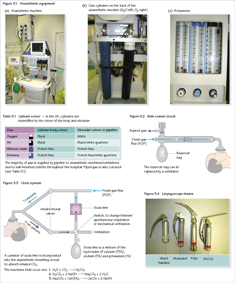
The anaesthetic machine (Figure 3.1a,b) provides anaesthetic gases in the desired quantities/proportions, at a safe pressure. Gas flow is set on the rotameter (O2, air, N2O) (Figure 3.1c), passing to the back bar. Here a proportion (splitting ratio) enters a vaporizer before returning to the main gas flow. The gas leaves the anaesthetic machine at the common gas outlet (CGO), reaching the patient via a breathing circuit.
Vaporizer
Part of the fresh gas flow (FGF) enters the vaporizer. Full saturation with volatile agent is achieved typically by a series of wicks to create a large surface area. As volatile anaesthetic is removed, energy is lost due to latent heat of vaporization. Temperature compensation occurs to maintain output, for example by use of a bimetallic strip which bends as the temperature alters.
Safety features
- Non-interchangeable screw threads (NISTs) prevent the incorrect pipeline gas being connected to the machine inlet.
- A pin index system is used to prevent incorrect cylinder connection.
- Barotrauma to both patient and machine is avoided by using pressure reducing valves/regulators and flow restrictors.
- The oxygen failure warning alarm is pressure driven and alerts of imminent pipeline or cylinder failure.
- Accurate gas delivery: flow delivered through the anaesthetic machine is displayed by a bobbin (Figure 3.1c) within a rotameter. The gas enters the cylinder at its base, forcing the bobbin higher, depending on the gas flow. This is a fixed pressure variable orifice flowmeter, that is the pressure difference across the bobbin remains constant whilst the orifice size increases further up the tapered tube. Each rotameter is calibrated for a specific gas as their viscosity (at low, laminar flow) and density (at higher, turbulent flow) affect the height of the bobbin. The bobbins have spiral gro/>
Stay updated, free dental videos. Join our Telegram channel

VIDEdental - Online dental courses


