Dental X-ray equipment, image receptors and image processing
• X-ray generating equipment – required to produce the X-rays
• Image receptors (film and digital) – required to detect the X-rays
• Image processing (chemical or computer) – required to produce the visual black, white and grey image.
Dental X-ray generating equipment
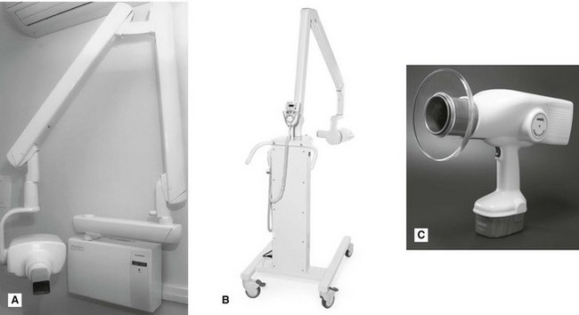
These dental units can either be fixed (wall, floor or ceiling mounted) or mobile (attached to a sturdy frame on wheels), as shown in Figs 3.1A and B. A recent development has been the production of hand-held dental units (Fig. 3.1C), particularly useful for domiciliary and forensic radiology.
Ideal requirements
Main components of the tubehead
A diagram of a typical tubehead is shown in Fig. 3.2. The main components include:
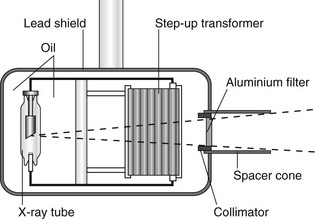
• The glass X-ray tube, including the filament, copper block and the target (see Ch. 2)
• The step-up transformer required to step-up the mains voltage of 240 volts to the high voltage (kV) required across the X-ray tube
• The step-down transformer required to step-down the mains voltage of 240 volts to the low voltage current required to heat the filament
• A surrounding lead shield to minimize leakage
• Surrounding oil to facilitate heat removal
• Aluminium filtration to remove harmful low-energy (soft) X-rays (see Fig. 3.3)
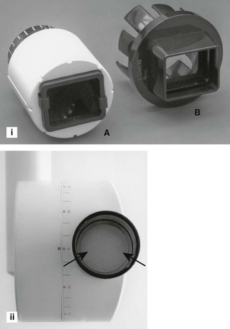
• The collimator – a metal disc or cylinder with central aperture designed to shape and limit the beam size to a rectangle (the same size as an intraoral image receptor) or round with a maximum diameter of 6 cm (see Figs 3.3 and 3.4)
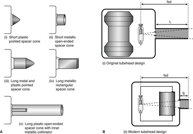
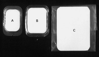
• The spacer cone or beam-indicating device (BID) – a device for indicating the direction of the beam and setting the ideal distance from the focal spot on the target to the skin. The required focus to skin distances (fsd) are:
It is the length of the focal spot to skin distance (fsd) that is important NOT the physical length of the spacer cone. Various designs are illustrated in Fig. 3.4.
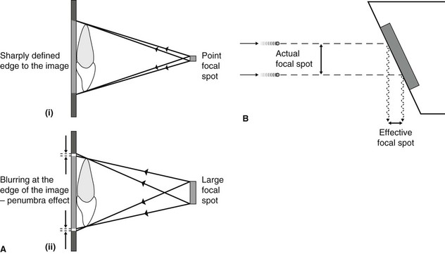
Focal spot size and the principle of line focus
As stated in Chapter 1, the focal spot (the source of the X-rays) should be ideally a point source to reduce blurring of the image – the penumbra effect – as shown in Fig. 3.5A. However, the heat produced at the target by the bombarding electrons needs to be distributed over as large an area as possible. These two opposite requirements are satisfied by using an angled target and the principle of line focus, as shown in Fig. 3.5B.
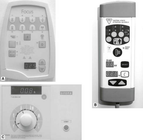
Main components of the control panel
Examples of three typical control panels are shown in Fig. 3.6. The main components include:
• The mains on/off switch and warning light
• The timer, of which there are three main types:
• An exposure time selector mechanism, usually either:
– numerical, time selected in seconds
– anatomical, area of mouth selected and exposure time adjusted automatically
• Warning lights and audible signals to indicate when X-rays are being generated
Circuitry and tube voltage
The mains supply to the X-ray machine of 240 volts has two functions:
• To generate the high potential difference (kV) to accelerate the electrons across the X-ray tube via the step-up transformer
• To provide the low-voltage current to heat the tube filament via the step-down transformer.
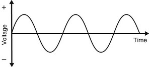
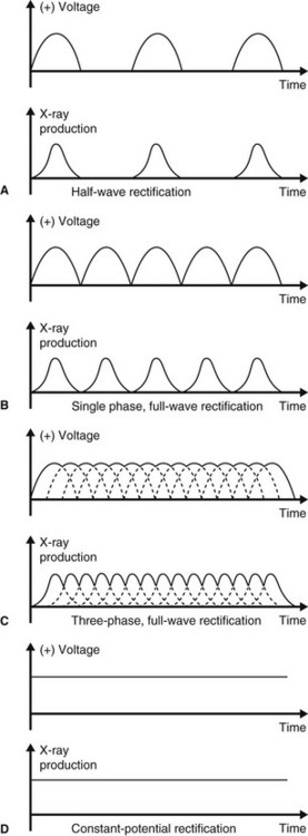
However, the incoming 240 volts is an alternating current with the typical waveform shown in Fig. 3.7. Half the cycle is positive and the other half is negative. For X-ray production, only the positive half of the cycle can be used to ensure that the electrons from the filament are always drawn towards the target. Thus, the stepped-up high voltage applied across the X-ray tube needs to be rectified to eliminate the negative half of the cycle. Four types of rectified circuits are used:
The waveforms resulting from these rectified circuits, together with graphical representation of their subsequent X-ray production, are shown in Fig. 3.8. These changing waveforms mean that equipment is only working at its optimum or peak output at the top of each cycle. The kilovoltage is therefore often described as the kVpeak or kVp. Thus a 50 kVp half-wave rectified X-ray set only in fact functions at 50 kV for a tiny fraction of the time of any exposure.
Other X-ray generating apparatus
The other X-ray generating equipment encountered in dental practices includes:
The main features and practical components of relevant machines are outlined in later chapters.
Image receptors
Radiographic film
• Direct-action or non-screen film (sometimes referred to as wrapped or packet film). This type of film is sensitive primarily to X-ray photons.
• Indirect-action or screen film, so-called because it is used in combination with intensifying screens in a cassette. This type of film is sensitive primarily to light photons, which are emitted by the adjacent intensifying screens by the photoelectric effect (see Ch. 2). They respond to shorter exposure of X-rays, enabling a lower dose of radiation to be given to the patient.
Direct-action (non-screen) film
Uses: Direct-action film is used for intraoral radiography where the need for excellent image quality and fine anatomical detail are of importance.
Sizes: Various sizes of film are available, although only three are usually used routinely (see Fig. 3.9).
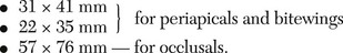
The film packet contents: The contents of a film packet are shown in Fig. 3.10. It is worth noting that:
• The outer packet or wrapper is made of non-absorbent paper or plastic and is sealed to prevent the ingress of saliva.
• The side of the packet that faces towards the X-ray beam has either a pebbled or a smooth surface and is usually white.
• The reverse side is usually of two colours so there is little chance of the film being placed the wrong way round in the patient’s mouth and different colours represent different film speeds.
• The black paper on either side of the film is there to protect the film from:
• A thin sheet of lead foil is placed behind the film to prevent:
– Some of the residual radiation that has passed through the film from continuing on into the patient’s tissues
– Scattered secondary radiation, from X-ray photon interactions within the tissues beyond the film, scattering back on to the film and degrading the image.
• The sheet of lead foil contains an embossed pattern so that should the film packet be placed the wrong way round, the pattern will appear on the resultant radiograph. This enables the cause of the resultant pale film to be easily identified (see Ch. 14).
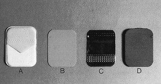
The radiographic film: The cross-sectional structure and components of the radiographic film are shown in Fig. 3.11. It comprises four basic components:
• A plastic base, made of clear, transparent cellulose acetate – acts as a support for the emulsion but does not contribute to the final image
• A thin layer of adhesive – fixes the emulsion to the base
• The emulsion on both sides of the base – this consists of silver halide (usually bromide) crystals embedded in a gelatin matrix. The X-ray photons sensitize the silver halide crystals that they strike and these sensitized silver halide crystals are later reduced to visible black metallic silver in the developer (see later)
• A protective layer of clear gelatin to shield the emulsion from mechanical damage.
Film orientation: The film has an embossed dot on one corner that is used to help orientation. Its position is marked on the back of the packet or can be felt as a raised dot on the front. The side of the film on which the dot is raised is always placed towards the X-ray beam. When the films are mounted, this raised dot is towards the operator and the films are then arranged anatomically and viewed as if the operator were facing the patient.
Film speed: The speed of the film determines how quickly it reacts to X-rays. Thus the faster the film, the less the exposure required for a given film blackening and the lower the radiation dose to the patient. It is determined by the number and size of the silver halide crystals in the emulsion and designated by the letters D, E and F. The larger the crystals, the faster the film, but the poorer the image quality.
Resolution: Resolution, or resolving power, is a measure of the radiograph’s ability to differentiate between different structures that are close together. Factors that can affect resolution include penumbra effect (image sharpness), silver halide crystal size and contrast. It is measured in line pairs (lp) per mm. Direct-action film has a resolution of approximately 10 lp per mm.
Indirect-action film
Uses: Film/screen combinations are used as image detectors whenever possible because of the reduced dose of radiation to the patient (particularly when very fine image detail is not essential). The main uses include:
Indirect-action film construction: This type of film is similar in construction to direct-action film described above. However, the following important points should be noted:
• The silver halide emulsion is designed to be sensitive primarily to light rather than X-rays.
• Different emulsions are manufactured which are sensitive to the different colours of light emitted by different types of intensifying screens (see later). These include:
– Standard silver halide emulsion sensitive to BLUE light
– Modified silver halide emulsion with ultraviolet sensitizers sensitive to ULTRAVIOLET light
• It is essential that the correct combination of film and intensifying screens is used.
• There is no orientation dot embossed in the film so some form of additional identification is required, e.g. metal letters, L or R, placed on the outside of the cassette or electronic marking.
• Indirect action film has a resolution of about 5 lp per mm.
Stay updated, free dental videos. Join our Telegram channel
VIDEdental - Online dental courses


