Radiographic Techniques
Gail F. Williamson, Kivanç Kamburo lu*, Suman Jai Sanghar, N. Jai Sanghar, Rinky Nacchyon, Apeksha Mainali, Ravikiran Ongole and B.N. Praveen
X-ray Beam Angulation and Alignment
Radiographic Infection Control
Radiation Safety and Protection
Intraoral Radiographic Techniques
➧. Standard Occipitomental view
➧. Parietoacanthial View (Waters’ View)
➧. Parietoacanthial View(Open Mouth Waters’ View)
➧. Modified Parietoacanthial Projection(Modified Waters’ View)
➧. Acanthoparietal Projection(Reverse Waters’ Method)
➧. Submentovertex View (Base or Full Axial Projection, Schuller Method)
➧. AP Axial Projection (Townes’ Method)
Lateral Oblique of the Body of the Mandible and Maxilla
➧. Transpharyngeal View(Parma Projection, Macqueen-Dell Technique)
➧. Lesser Known/Forgotten Extraoral Radiographic Techniques
Townes’ Method or AP Axial Projection
Axiolateral Oblique Projection
Dentomaxillofacial Cone-Beam Computed Tomography (CBCT)
Principles of Magnetic Resonance Imaging
Methods for Obtaining Spatial (Tomographic) Resolution of MR Signals
Different Types of Scanners Used
Main Indications for Ultrasound in the Head and Neck
Intraoral Radiography
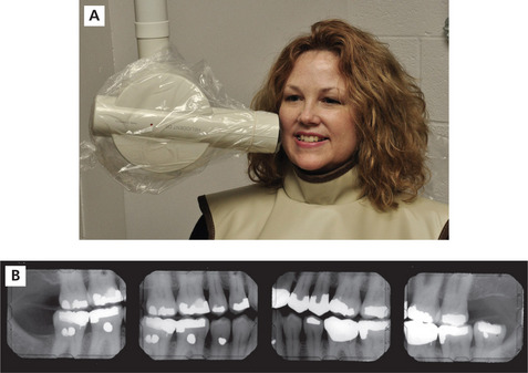
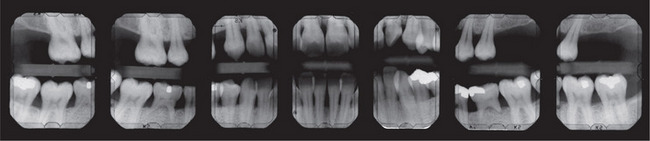
Intraoral radiography is an important tool for proper diagnosis and treatment. Intraoral radiographs allow the clinician to view the teeth and supporting structures revealing conditions that may not be apparent clinically. Intraoral radiography is accomplished by placement of a small image receptor (IR) inside the mouth behind the teeth and structures of interest with the X-ray beam aligned externally over the corresponding area. Available intraoral receptors include radiographic film, rigid digital sensors and photostimulable phosphor plates. Intraoral radiography involves the acquisition of periapical and bitewing images that can be combined to form surveys. Periapical radiographs record the entire tooth or several teeth and the surrounding structures including the apical regions, the trabecular bone, the periodontal ligament space and the lamina dura. By contrast, bitewings record the crowns, proximal contacts of the teeth and the alveolar bone crests. Typically, a complete or full-mouth survey consists of 14–16 periapicals and 2–4 posterior bitewings (Figure 1A, B). In addition to periapicals and bitewings, occlusal radiographs can be taken to record a broad region of either the maxilla or mandible. In most instances, occlusal images are supplemental views taken to record a larger area or to localize an object.
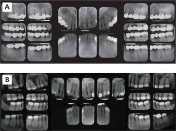
Figure 1 A typical full-mouth survey consists of 14–16 periapicals and 2–4 bitewings. (A) Full-mouth survey taken with size 2 film receptors. (B) Full-mouth survey taken with size 1 and 2 film receptors
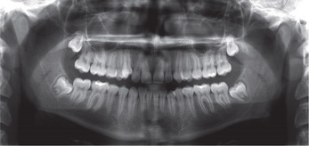
Intraoral radiographs can be combined with or augmented by extraoral radiographs. In extraoral radiography, both the receptor and X-ray source are housed outside the oral cavity. Extraoral radiography requires specialized equipment and can be accomplished with intensifying screen-film combinations or with digital imaging systems. The panoramic image is the most common extraoral projection which provides a more complete view of the maxilla and mandible, the maxillary sinuses and the temporomandibular joints (TMJ) (Figure 2). Cephalometric radiography is more task-specific and includes a variety of skull projections. The most common application of cephalometric radiography is the lateral skull projection used in orthodontics. The lateral skull view is used to evaluate structures, monitor growth and development and track treatment progress. Cone-beam computed tomography (CBCT) is the most recent addition to extraoral dental imaging. CBCT is indicated when three-dimensional (3D) imaging is necessary to evaluate and plan treatment in situations such as implant placement, failed endodontic treatment, pathological conditions, difficult surgical procedures and evaluation of craniofacial anomalies.
Intraoral X-ray Machine
The typical intraoral dental X-ray machine used to expose intraoral receptors operates at 60 or 70 kilovolts (kV), 4–8 milliamperes (mA) with variable exposure time settings (Figure 3A, B). Kilovoltage controls the penetrating power of the X-ray beam and image contrast or differences in darkness. Milliamperage and time control the number of X-rays and image density or the overall darkness of a radiographic image. Most intraoral X-ray machines have fixed kilovoltage and milliamperage settings which permit adjustment of the exposure time only. The length of the exposure time is dependent on a number of factors including the kilovoltage and milliamperage settings, collimation of the X-ray beam, patient size, area of interest and the type of receptor.
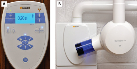
Figure 3 (A) Intraoral dental X-ray machine control panel. (B) X-ray head and PID; HeliodentPlus Sirona Dental Systems, Inc., Long Island City, New York
Collimation restricts the size of the X-ray beam, reduces patient exposure and improves image quality by reduction of scatter radiation and minimizing penumbra production. Collimation is accomplished with open-ended position indicating devices (PIDs) that are either circular or rectangular in shape and vary in length from 20 to 40 cm (Figure 4). Long rectangular collimation restricts the X-ray beam andreduces the volume of tissue exposed on the skin surface the most and, therefore, is recommended for periapical radiography and bitewing radiography when practicable.
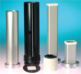
Figure 4 Collimation restricts the size of the X-ray beam and the area of patient skin exposure. It can be accomplished with a variety of devices including PIDs, metal devices that clip into ringed instruments or that slide onto a PID. Rectangular collimation is optimal
When selecting the exposure time, consideration should be given to the overall size of the patient as well as the area of interest. Recommended exposure time settings are designed for the average adult patient. For adult patients smaller than average, the exposure time for each area can be reduced by one step and for larger than average, increased by one step. Exposure time settings for children are considerably less than for adults and frequently can be accessed by selecting a child icon on the control panel (Figure 3A). Exposure time increases as the survey progresses from the anterior to the posterior regions of the mouth. Digital receptor exposures follow these same general principles but the time settings are lower for each area when compared to film. The speed of the receptor has an influence on the exposure time as well. Speed indicates the sensitivity of a receptor to X-rays; the faster the receptor, the less the radiation required to produce a diagnostic image. Currently, F-speed is the fastest film available for intraoral radiography, providing significant dose reduction and comparable performance compared to D-speed film. Digital receptors, both rigid sensors and phosphor plates, provide equal or greater dose savings than F-speed film with equivalent diagnostic utility. Intraoral X-ray machines manufactured today are compatible with film, rigid sensors and phosphor plates.
X-ray Beam Angulation and Alignment
The vertical angulation of the X-ray beam varies and is dependent on the tooth, dental arch, oral anatomy and intraoral technique used. Vertical angulation is adjusted by moving the X-ray head and PID up or down. Positive vertical angulations are used for maxillary periapicals and bitewings and negative vertical angulations are used for mandibular periapicals. Positive vertical angulations position the X-ray head above horizon with the PID directed downward while negative vertical angulations position the X-ray head below horizon with the PID directed upward (Figure 5A, B). Most dental X-ray machines have an angle meter on the X-ray head to indicate the degree of the vertical angulation with horizon designated as 0. Vertical angulation controls the length dimension of the recorded image. Errors in vertical angulation produce images that either shorten or lengthen the actual vertical dimension of the structures.
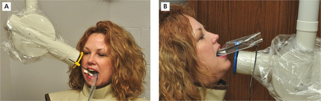
Figure 5 Vertical angulation. (A) Positive vertical angulation is used for maxillary periapicals as demonstrated by this premolar placement. (B) Negative vertical angulation is used for mandibular periapicals as demonstrated by this incisor periapical placement
The horizontal angulation is adjusted by moving the X-ray head and PID anteriorly or posteriorly (forward or backward) along the horizontal plane. The horizontal angulation is directed proximally for all intraoral views and follows the curvature of the dental arches. This places the X-ray beam perpendicular to the horizontal plane of the teeth of interest. Errors in horizontal angulation result in overlapping of the proximal surfaces of the teeth and width distortion such that the teeth contacts and alveolar bone crests cannot be properly visualized.
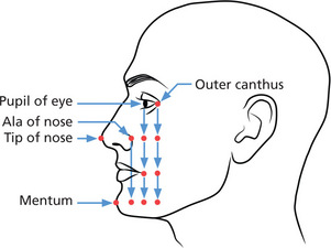
In order to expose the entire receptor, the center of the X-ray beam, known as the central ray (CR), is directed toward the middle of the receptor which is represented externally by facial anatomic points as illustrated in Figure 6. Failure to properly center the X-ray beam over the receptor produces a partial image. The unexposed portion is called a ‘cone cut’, a term that dates back to the time when closed cones were used rather than open-ended PID collimators to direct the X-ray beam. Closed cones are no longer used as they produce excessive scatter radiation that significantly increases the radiation dose delivered to the patient.
Radiographic Infection Control
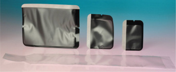
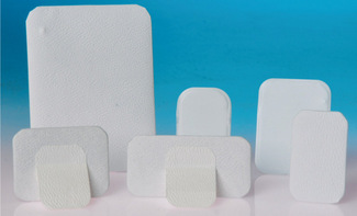
Disposable or radiographic instruments that can be heat-sterilized should be used for intraoral radiography. Intraoral digital receptors that cannot be heat-sterilized must be covered with a FDA (Food and Drug Administration)-cleared barrier (Figure 7) and cleaned and disinfected with an EPA-registered hospital disinfectant with intermediatelevel activity between patients. Protective plastic barrier envelopes are used to cover radiographic film and phosphor plates during placement in the mouth (Figure 7). After exposure, contaminated external barrier must be disinfected before dropping the film or plate out of the barrier in preparation for processing. It is best to consult manufacturer instructions for guidance on digital receptor handling and disinfection practices.
Radiation Safety and Protection
ALARA (As Low As Reasonably Achievable) is the guiding principle in radiation safety and protection. It is the ethical and professional obligation of dental professionals to keep the radiation dose delivered to the patient to a minimum. Although the risk of intraoral radiography is thought to be very small, it is not risk-free and the effects of radiation are cumulative. The measures most effective in dose reduction include the use of selection criteria, fast film or digital receptors for intraoral radiography, rare earth screen-film combinations or digital receptors for extraoral radiography, rectangular collimation of the X-ray beam and patient shielding.
Preliminary Procedures
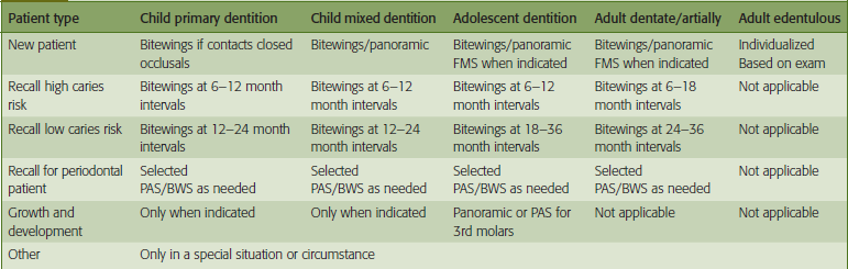
Before radiographs are prescribed, a complete medical and dental history must be taken, reviewed and the chief complaint identified. The dentist should examine the dentition to determine if radiographs are indicated. If radiographs are necessary, the type and number of projections should be identified. The American Dental Association (ADA) and the FDA have established guidelines for the selection of dental radiographic examinations in the United States. Dental radiographs should be prescribed according to these guidelines and taken for diagnostic and treatment purposes only. Selection criteria guidelines are based on the evidence of disease patterns and information obtained from the patient’s medical and dental history, clinical signs and symptoms of disease, risk factors, age and dentition, and new or recall patient status. Only bitewing radiographs are recommended on time-based regimens as determined by patient risk factors for caries. See Table 1 for a summary of these guidelines. Typically, radiographic procedures are delegated to qualified dental staff (dental assistant and/or dental hygienists) for completion.
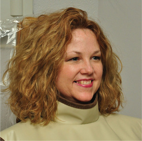
Once the appropriate survey has been determined, the patient should be prepared for the procedure. Facial jewelry, intraoral prostheses and eyeglasses should be removed and safely stored. The patient should be protected with a lead apron and thyroid collar, provided with an explanation of the purpose of the examination and given instructions to elicit cooperation (Figure 8). Preferably, the patient is seated in an upright position with the midline centered and the occlusal plane parallel to the floor for maxillary periapicals and bitewings and the chin raised so that the mandibular arch is parallel to the floor for mandibular periapicals. The exposure time should be set for the area before placement of the receptor inside the mouth. When ready for exposure, the clinician should practice radiation safety measures to avoid occupational radiation exposure. Once the survey is acquired, proper processing techniques should be followed as dictated by the selected image receptor. The clinician must ensure that the processed radiographic images are properly arranged in the film mount or computer image template according to the ADA standard. This standard involves labial mounting and viewing of radiographic images according to the patient’s right and left sides of the dentition. Attention to correct tooth order, proper location of surrounding anatomical structures and observation of restorative treatments and/or missing that match from periapical to periapical and/or periapical to bitewing will ensure accuracy of arrangement.
Intraoral Radiographic Techniques
Paralleling technique
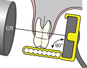
The paralleling technique requires placement of the receptor parallel to the tooth or teeth of interest both in the vertical and horizontal planes. The X-ray beam is directed so that it strikes both the tooth and the receptor at a right angle (Figure 9). Typically, the paralleling technique is accomplished with ringed instruments that aid the clinician in establishing the correct object to receptor relationship, horizontal and vertical angulation and centering of the X-ray beam (Figure 10). There are a variety of ringed instruments commercially available with designs for all three types of intraoral receptors. Proper assembly and parallel receptor placement to the area of interest are necessary for optimal results. A standard bite-block can be used for the paralleling technique as long as the clinician has the skill to align the PID accurately.
Bisecting angle technique
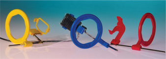
The bisecting angle technique is based on Cieszynski’s rule of isometry or the geometry of equilateral triangles. This rule states that two triangles are equal if they share a common side and two equal angles. Applied to periapical radiography, a tooth and its projected image will be equal in length if the X-ray beam is directed at a right angle to the common side or bisecting plane that divides the triangle into two equal halves or equilateral triangles (Figure 11). Care must be taken to accurately determine the bisecting plane to avoid errors in vertical angulation. Approximate vertical angulations used for each periapical are listed in Table 2. The horizontal angulation and centering of the X-ray beam remain the same as with the paralleling technique. There are instruments commercially available for the bisecting angle technique for both film and digital receptors (Figure 12). Bisecting angle technique requires more technical skill and as such, more retakes tend to occur than with the paralleling technique.
Table 2
| Periapical view | Maxillary | Mandibular |
| Incisor | + 40° to +50° | −5° to −15° |
| Lateral-canine | + 40° to +50° | −5° to −15° |
| Premolar | + 25° to +35° | −10° to −15° |
| Molar | + 20° to +30° | + 5° to −5° |
Approximate vertical angulations
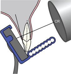
Figure 11 Bisecting angle technique directs the central ray at a right angle to the plane that divides the angle formed by the teeth and receptor
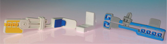
Figure 12 Many types of bisecting angle instruments are commercially available for film, rigid sensors and phosphor plate receptors. Snap-A-Ray® Xtra, Stabe Biteblock® and Eezee-Grip® Digital sensor holders are shown from left to right. Dentsply Rinn, Elgin, Illinois
Radiographic film
Radiographic film is the traditional medium for recording intraoral images (Figure 13). It consists of a blue-tinted plastic base material coated with a double emulsion of gelatin and silver halide crystals, predominantly silver bromide. The film has a dot convexity that indicates the exposure side and aids in proper arrangement and mounting of the processed radiographs. The film is wrapped with an internal black paper with a lead foil on the rear or non-exposure side and covered externally with either a plastic or paper material to protect the emulsion from light and moisture. The exposure side of the film packet is white and the non-exposure side is two-toned with colors used to indicate speed and single or double film packet. Once exposed to radiation, the emulsion captures and stores the latent image until the image is made visible by chemical processing. Those silver halide crystals exposed to radiation are reduced to metallic silver by the developer solution reducing agents and form the radiolucent components of the image. The non-exposed, undeveloped silver halide crystals are removed by the fixer solution clearing agent and become the radiopaque components of the image. Typically film-based images are processed by automatic processing systems that develop, fix and dry radiographic film in approximately 5.5 minutes. The processed radiographs are ready for arrangement and mounting after exiting the processor. Care must be taken to properly maintain the processor utilizing regular solution replenishment, cleaning and solution change regimens. Processing errors are a common cause of retakes in filmbased imaging.
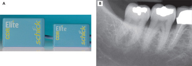
Direct digital receptors
Direct digital receptors are rigid, wired receptors in the form of the charge-coupled device (CCD) or complimentary metal oxide semi-conductor (CMOS) detector (Figure 14A, B). The primary difference between the two devices is the manner in which the latent image is transferred to the read-out amplifier for display. The active image area is smaller compared to film or phosphor plates so the area of coverage is slightly diminished. These rigid devices are area arrays composed of a matrix of pixels with each pixel functioning as an electron well. When the sensor is exposed to radiation, the energy that penetrates through the structures is deposited in the electron well in that location. The intensity of the energy or signal determines the brightness or density of the image in each area. The digital data is processed by the computer and the visible image can be viewed on the monitor almost instantly. Rigid digital sensors are reusable receptors that cannot be sterilized. As indicated previously, they must be properly disinfected and covered with a barrier to avoid direct contact with oral fluids. When positioning the receptor in the mouth, the wire should be oriented toward the occlusal plane for vertically placed anterior periapicals and directed anteriorly for horizontally placed posterior periapicals.
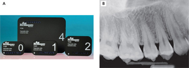
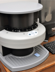
Photostimulable phosphor plates
Photostimulable phosphor plates (PSPs) or storage phosphor plates (SPPs) are wireless digital receptors that handle similar to film (Figure 15A, B). A separate plate is needed for each exposure and a processing step is required before the images can be viewed on the computer monitor. Phosphor plate receptors have a single emulsion coated on the exposure side of the plate composed of europium-activated barium fluorohalide. Rather than an identification dot, plate receptors have a letter or number to identify the exposure side of the receptor. Care must be taken to prevent abrasion, crimping or creasing of the emulsion to avoid permanent image artifacts and frequent plate replacement. Once the plate is exposed, the latent image is stored in the emulsion until the plate is scanned by a helium laser beam (Figure 16). When the phosphor plate is scanned, it emits light in proportion to the exposure received. The light detected by the photomultiplier is converted from analog-to-digital data and the visible image is displayed on the monitor for viewing. The scanning takes several seconds causing a slight delay between image capture and display. Before reuse, the plate must be erased by white light to remove any remnant image. Typically, the plate is erased prior to exit from the scanning unit. The primary advantages of the phosphor plate are its thin, wireless construction while the disadvantages are susceptibility to emulsion scratches producing artifacts and delayed image viewing.
Intraoral Radiographic Procedures
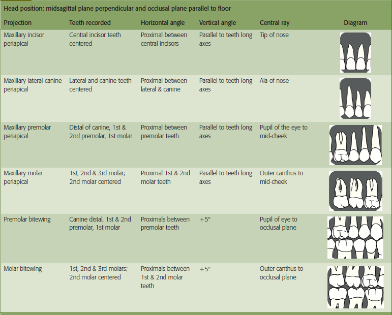
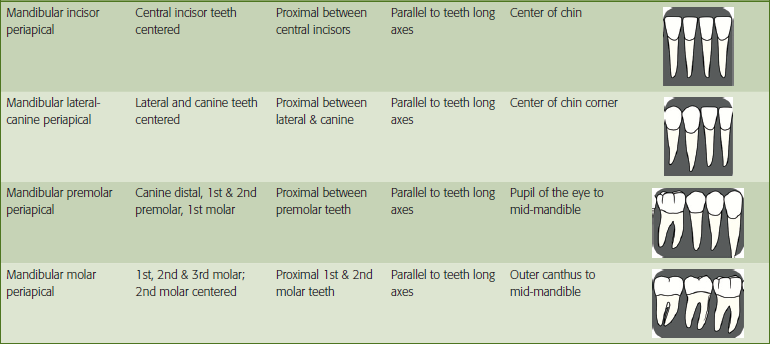
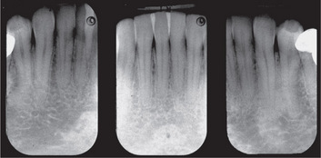
Periapical radiography
Periapical images provide information about tooth morphology, apical proximity to anatomic structures, abnormalitiesof the teeth and supporting structures such as carious lesions, periodontal bone loss and periapical and bony pathoses. Periapical radiographs can be taken in any area of the mouth. There are classic placements for the incisor, canine, premolar and molar teeth as outlined in Table 3. When taking a full-mouth survey, it is best to take the anterior periapicals first. This allows the patient time to adjust to the procedure before taking the posterior periapicals which tend to be more difficult for some patients. Anterior periapicals are placed in the vertical dimension with the receptor identification dot or marker located in the coronal aspect of the image. For adult patients, the size 1 or 2 receptor can be used. The size 1 receptor is preferred for narrow or crowded dental arches. Anterior periapicals are used to record the central incisor, lateral incisor and canine teeth (Figure 17). Posterior periapicals are oriented in the horizontal dimension and are used to record the distal aspect of the canine, premolar and molar teeth (Figure 18). For adult patients, the size 2 receptor is the standard for posterior projections.
Bitewing radiography
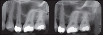
Bitewing radiographs are most frequently taken in the posterior regions of the mouth of the premolar and molar teeth for the detection of proximal caries and alveolar bone loss (Figure 19A, B). For adult patients, the size 2 receptor is preferred. Bitewings can be oriented in either the horizontal or vertical plane with the receptor positioned parallel to the teeth crowns. Horizontal bitewings are the most common but vertical bitewings are taken particularly when moderate or greater alveolar bone loss is present. Anterior bitewings can be taken to view bone levels in the anterior segments of the mouth as well (Figure 20). A size 1 receptor is used to capture incisor and lateral-canine bitewing views. The clinician can select traditional tabs or instrument holders to accomplish the bitewing survey. The vertical angulation used for tab bitewings ranges from + 5° to +10°. The most common error associated with bitewing radiography is horizontal overlap which can render the image non-diagnostic.
Occlusal radiography
Topographical occlusals
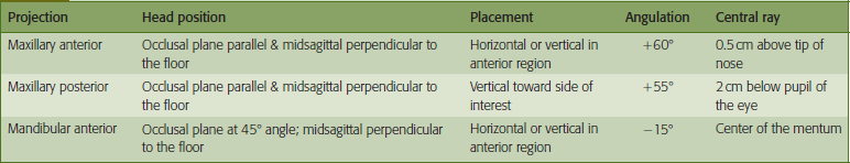
Topographical occlusals are based on the bisecting angle technique. Topographical occlusals have the appearance of a large periapical view of the teeth and surrounding structures. Typical applications include recording bilateral impactions of the permanent canine teeth, mesiodens or large periapical or bony lesions. Topographical occlusal projections can be applied to pediatric imaging by using a size 2 receptor and reduction of the exposure time. In addition, anterior periapical views can be taken using topographical occlusal technique when mouth opening is limited or the arch is extremely narrow or crowded. In these instances, a size 2 receptor is oriented vertically. Table 4 summarizes the basic technical aspects of topographical occlusal projections.
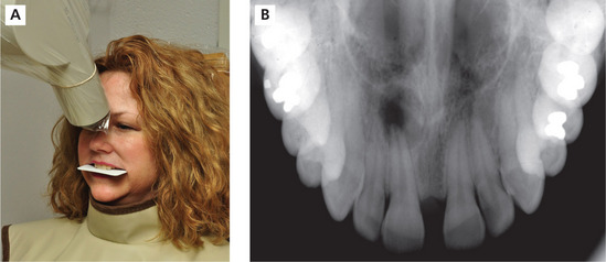
Topographical maxillary anterior occlusal
The patient’s head is aligned with the occlusal plane parallel to the floor and the midsagittal plane perpendicular to the floor. The receptor can be positioned horizontally or vertically dependent on the mouth size and arch width. With the mouth opened slightly, the receptor is placed against the maxillary occlusal surfaces with the dot convexity toward the palate and positioned labially. The patient bites together lightly to secure the receptor. The approximate bisecting angle for this projection is +60° with the horizontal angle directed through the proximal contacts of the maxillary central incisors. The central ray of the X-ray beam enters through a point located just above the tip of the nose. Generally, the exposure time is the same time as the maxillary incisor periapical for the selected receptor (Figure 21A, B).
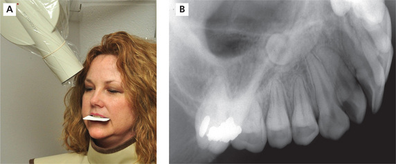
Topographical maxillary posterior occlusal
As with the anterior occlusal, the patient’s head is positioned with the occlusal plane parallel to the floor and midsagittal plane perpendicular to the floor. The receptor is oriented vertically toward the side of interest and placed against the occlusal surfaces of the maxillary teeth with the dot placed anteriorly. The receptor should extend approximately 1 cm beyond the buccal surfaces of the posterior teeth and inserted posteriorly until it contacts the anterior ramus. The receptor is maintained in position by light patient biting pressure. A +60° vertical angulation is used with the horizontal angle directed through the premolar teeth contacts and the central ray entering about 2 cm below the pupil of the eye. This projection will record one quadrant of the maxillary teeth and alveolar ridge (Figure 22A, B).
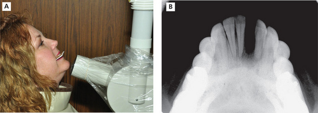
Topographical mandibular anterior occlusal
For the mandibular projection, the patient’s head is tilted back until the occlusal plane is at a 45° angle above horizon. The clinician can align the X-ray head at a −45° angle to use as a comparison to check for proper head position. The occlusal plane should be parallel to the open end of the PID. The midsagittal plane is positioned perpendicular to the floor. The receptor can be positioned horizontally or vertically as needed. With the mouth opened slightly, place the receptor against the occlusal surfaces of the mandibular teeth with the dot convexity toward the tongue and positioned labially. The patient bites together lightly to secure the receptor. The approximate bisecting angle for this projection is −15°. The horizontal angle is directed through the proximal contacts of the mandibular incisor teeth and the central ray is directed through the center of the mentum. The exposure time is the same time as the mandibular incisor periapical for selected receptor (Figure 23A, B).
Cross-sectional occlusals
Cross-sectional occlusals are most commonly taken for the purposes of object localization or to view the buccolingual aspect of the dental arches. Cross-sectional occlusal technique directs the central ray at a right angle to the receptor. The maxillary cross-sectional occlusal requires an X-ray machine capable of 90 kV t/>
Stay updated, free dental videos. Join our Telegram channel
VIDEdental - Online dental courses


