CHAPTER 26 Cephalometrics and Facial Esthetics: The Key to Complete Treatment Planning
The primary aim of cephalometric analysis is to localize malocclusion within a tracing of facial bone and soft tissue structures. The analysis is performed by using standardized cephalometric landmarks to construct lines, angles, and imaginary planes, which permits linear and angular assessments of dental and facial relationships as seen on radiographic films of the head and face. These findings are compared with established normal values, and an individualized treatment protocol is developed for orthopedic, orthodontic, and orthognathic therapies.
Most biologic variables are randomly distributed in the population and can be graphically illustrated by a bell-shaped curve (Fig. 26-1). Within this curve, approximately 70% of any given population lies within 1 standard deviation of the mean, whereas 95% of the group falls within 2 standard deviations. Throughout this chapter, the statistical concept of standard deviation is referred to as clinical deviation (CD).
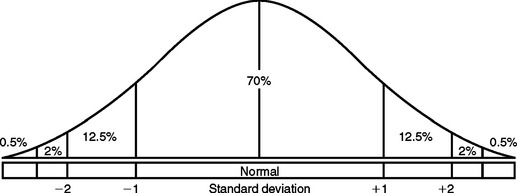
Figure 26-1 Bell-shaped curve illustrating the approximate distribution of biologic variables in the general population.
RADIOGRAPHIC TECHNIQUE
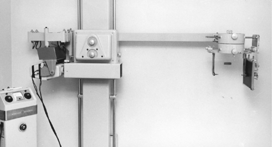
This standardization requires that the equipment include a headholder (cephalostat) and an x-ray tube positioned at a distance of 60 inches from the mid sagittal plane of the subject and that the distance from the midsagittal plane of the patient to the film be approximately 7.5 inches (Fig. 26-2). The cephalostat maintains a reproducible spatial relationship with respect to the position of the patient’s head, the film, and the x-ray source. The most common device uses a counterbalanced beam with the radiographic tube on one end and the cephalostat on the other. This entire unit can be adjusted vertically to compensate for variations in patient height.
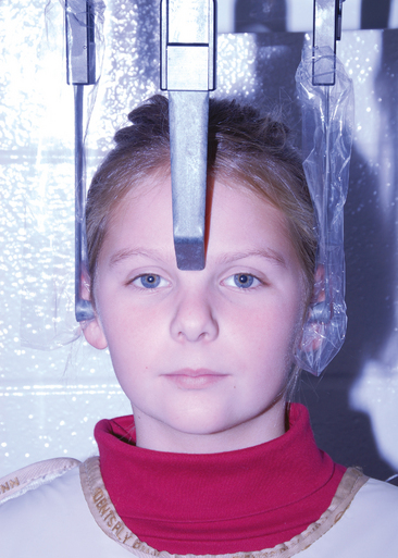
The patient is positioned in the cephalostat by means of laterally adjusted ear rods and a vertically adjusted nasal piece (Fig. 26-3). The nasal piece allows the clinician to orient the patient’s head so that the Frankfort horizontal plane (a plane extending from the tragus of the ear to the inferior border of the orbital rim) is parallel to the floor. The ear posts should be centrally aligned to the source of radiation so that a transporionic axis is established.
LATERAL HEAD FILM
For a lateral head radiograph, the patient is first positioned so that the left side of the face is tangent to an 8- by 10-inch film cassette, which permits less magnification and less distortion of the left-sided structures (Fig. 26-4).
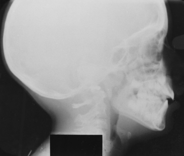
Grids and intensifying screens are accessories used to improve the quality of the radiographic image. Rare-earth intensifying screens allow for a reduction of radiographic exposure while increasing the clarity of the radiographic image. Because the film range does not provide for sharp skeletal and soft tissue contrast, a movable aluminum screen attached to the cassette must be used over the soft tissue profile area to reduce the radiation and provide a better differential contrast between the two tissue types.
FRONTAL (POSTEROANTERIOR) FILM
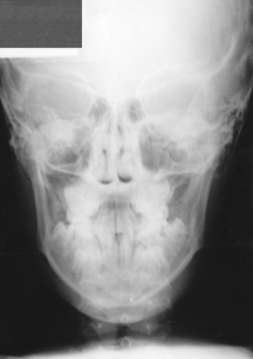
Most diagnostic features related to vertical and anteroposterior (AP) problems are evident from the lateral film, though severe maxillary transverse deficiencies or facial asymmetries may be better diagnosed by the use of a posteroanterior (PA) film (Fig. 26-5). The patient is oriented facing the film cassette, with the ear rods and nasion piece positioning the patient so that the midsagittal and Frankfort planes are at right angles to the film cassette. After the patient’s head is positioned so that the central x-ray beam passes through the head at the level of the transporionic axis and at its midpoint, the film cassette is moved into contact with the patient’s nose. Because more radiation is required for this view, the milliamperage must be increased over that used in the lateral film technique.
CEPHALOMETRIC TRACING TECHNIQUE
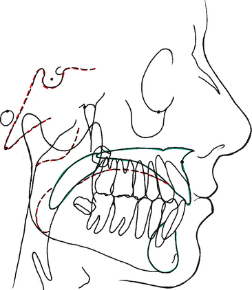
Fig. 26-6 depicts a lateral cephalometric tracing. The lateral tracing should include the soft tissue outline, bony profile, outline of the mandible, posterior and anterior cranial base, odontoid process of the axis, anterior lip of the foramen magnum, clivus, planum orbitale, sella turcica, orbit, pterygomaxillary fissure, floor of the nose, roof of the palate, and body of the hyoid bone. In addition to the bony tissues, at least the first permanent molars as well as the most anterior maxillary and mandibular incisors are commonly included. In certain situations it may be desirable to trace other teeth or the complete dentition as shown in Fig. 26-6.
A PA cephalometric radiograph, as illustrated in Fig. 26-5, can be of significant diagnostic value in cases demonstrating mandibular displacement, facial asymmetry, severe posterior crossbite, or other types of bony dysplasia. Cephalometric analysis and a thorough and systematic clinical examination of these patients often reveal malocclusions accompanied by mandibular shifts when the patient is in maximum occlusion.
The PA radiograph is traced in the same manner as the lateral film. Fig. 26-7 illustrates the important skeletal and dental structures that must be traced for an accurate and complete analysis.
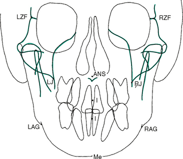
Figure 26-7 Frontal (posteroanterior) cephalometric tracing (see also Fig. 26-10). ANS, Anterior nasal spine; I, I (incisor) point; LAG, left antegonial notch; LJ, left jugal process of maxillary tuberosity; LZF, left zygomaticofrontal suture; Me, menton; RAG, right antegonial notch; RJ, right jugal process of maxillary tuberosity; RZF, right zygomaticofrontal suture.
REFERENCE POINTS FOR LATERAL TRACING
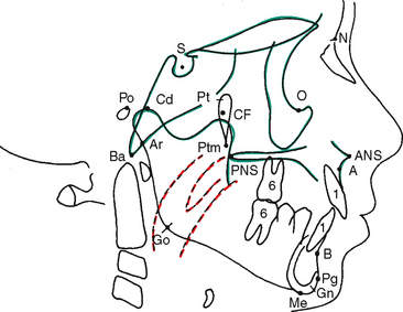
The ultimate diagnostic value of the cephalometric analysis is dependent on the initial accurate identification and localization of anatomic and anthropologic points (Fig. 26-8). These landmarks are used to construct the lines, angles, and planes used to make a two-dimensional assessment of the patient’s craniofacial and dental relationships. Although each analysis is completed in two dimensions, when the lateral analysis and the PA analysis for the same patient are considered together, a threedimensional simulation emerges to contribute to the overall diagnosis and treatment plan. The following reference points are used in this chapter (see Fig. 26-8):
REFERENCE LINES, ANGLES, AND PLANES
Linear assessment is derived when two reference points are connected. Angular measurements are possible when three points are used. Planes (and some lines) are actually imaginary when the cephalometric tracing is viewed because the planes are at right angles to the tracing and can be seen only as a line on the two-dimensional tracing (Fig. 26-9). In cephalometric analysis, the dentist must become accustomed to thinking in three dimensions while viewing a two-dimensional representation. Therefore a point on the tracing may not only be a point but also may represent a line (or axis). A line on the tracing may actually be a line (or axis) or it may represent a plane.
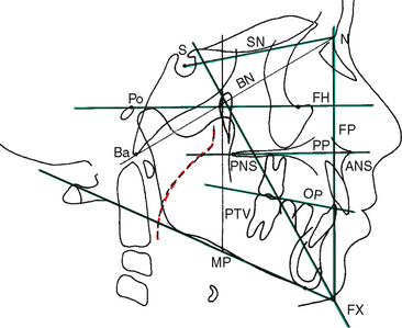
The basic units of cephalometric analysis are angles and distances (lines). Measurements may be treated as absolute values, or they may be related to one another and expressed as relative proportions. These measurements and interrelationships provide the basic framework for describing craniofacial abnormalities. The following definitions help explain the planes of reference used in this chapter (see Fig. 26-9).
INTERPRETATION OF MEASUREMENTS
The objectives of cephalometric interpretation are summarized as follows:
Stay updated, free dental videos. Join our Telegram channel
VIDEdental - Online dental courses


