2
Three – Dimensional Surface Acquisition Systems for Facial Analysis
Surface acquisition systems for facial imaging are improving at a rapid pace as a result of the introduction of sophisticated three – dimensional (3D) devices into the market. These advancements also mean that the soft tissues of the face can be evaluated in a faster, less invasive manner compared with conventional anthropometric techniques.
Although there have been significant investigations in the past on facial skeletal structures, the number of papers focusing on and analyzing soft tissue morphology and growth is comparatively small in relation to the general oral and maxillofacial literature.1 Yet the external profile is by far the most visible entity that clinicians and lay people perceive, and on which they formulate judgments. In the modern day, with a greater emphasis being placed on the balance between the hard and soft tissues, it is important to have reliable and available data on the external soft tissue profile. Most of the available data on the changing soft tissue profile has been obtained from cephalometric data, with a smaller number of research data being obtained from limited 3D data.
A number of reviews have been written on the use of 3D technology in dentistry and oral maxillofacial surgery.2–5 This chapter will, however, focus on imaging devices that have been used to capture facial surface morphology, and explore their advantages and disadvantages. A discussion on the applications to medical imaging will also be discussed.
TYPES OF SURFACE ACQUISITION SYSTEM
There are numerous ways of acquiring the facial soft tissue surface. In this chapter, surface imaging devices may be classified in the manner set out in Table 2.1.
Table 2.1 Tabular representation of surface imaging devices
| Photogrammetry | Traditional stereo – photogrammetry |
| Lasers | Fixed units |
| Medical Graphics and Imaging Group, UCL | |
| Cyberware Laboratory 3030/SP | |
| Others | |
| Structured light | Portable and mobile |
| Minolta Systems (Model 700, 900, 910, 9i) | |
| Polhemus hand – held (Fastscan) | |
| Structured light | Single camera |
| Multiple camera | |
| Moir é patterns | |
| OGIS Range Finder RFX – IV | |
| CAM, three – dimensional Shape system | |
| C3D – dimensional stereo – photogrammetry (Glasgow) – computer aided | |
| 3dMDface system | |
| Others | |
| Video – imaging | Motion – Analysis |
| Three – dimensional cephalometry | |
| Computed tomography scans | |
| Cone beam computed tomography | |
| Others | Magnetic resonance imaging |
| Ultrasound |
Traditional stereo – photogrammetry
Photogrammetry is the science of measurements of photographs, reconstructs the measurements of twodimensional or 3D structures from photographic reproductions6 and it has been used in medicine and dentistry since the 1940s.7 Tanner and Weiner modified and standardized this technique so that certain anthropometric dimensions could be measured to a degree of accuracy similar to direct methods. 8 Stereophotogrammetry is a technique that uses two or more cameras configured as a stereo- pair to obtain 3D coordinates of facial morphology. Early photogrammetric methods utilized techniques used by cartographers that incorporated contour mappings with varying subintervals. It was therefore often laborious, tedious, and expensive to map the facial structures in three dimensions.9-11 These techniques have also been applied to volumetric analysis and the faces.12,13
Stereo- photogrammetry, as already explained, refers to combining multiple views of photos to form a 3D image. For the purposes of this chapter, a light pattern projected onto a face will be classified as a structured light system. Beard and Burke introduced a method in 1967 that projected a radial grid onto the face.14 This gave numerous points of intersecting measurements and correspondence. Two stereometric cameras and a special flash unit mounted between the lens systems were required. Ras and co workers15,16 described the use of two semi- metric cameras mounted 50 cm apart on a frame with a positioned convergence angle of 15 degrees. A flash spot was positioned between the cameras, and a grid was projected onto the face. This grid facilitated the registration of the two photographs to create a perception of depth. These systems were checked for reliability and validity and used for the analysis of patients with cleft lip and palate and facial asymmetry.15,17
Laser scanning
In recent years, laser scanning has become a commonly used technique in acquiring 3D data from objects in the engineering industry.18 It is a valid and reliable technique that is used to detect minute and microscopic defects in the automotive and aerospace industries.
Laser technology utilizes optical principles and essentially is an active stereoscopic technique in which the distance of the object is computed by means of a directional light source and detector. A laser beam is “deflected” from a mirror onto a scanning object. The resultant deflection angle of the laser beam may be calculated by simple trigonometry. As the laser beam is projected onto the physical object, the beam is scattered, and this is then captured on a detector. The distance between the object and the detector and source can be calculated by geometric principles. The data may be translated into simple x-, y-, z-coordinates.
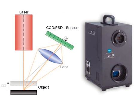
There are two broad classifications of laser devices for 3D acquisition according to the source of the beam. These are commonly known as singlepoint and slit scanners. Due to the time required to scan the object, as well as the optical and mechanic simplicity, a slit scanner (with a projection of a plane line) is the more practical solution for capturing facial morphology.18 An example of the principle of laser triangulation and the laser imaging system is shown in Figure 2.1. Other laser imaging devices (time – of -flight systems) are also available but will not be mentioned here.
Figure 2.1 Principles of laser triangulation and example of a laser scanning system.
Fixed units
The Medical Graphics Imaging Group s ystem from University College London
Moss and co-workers19 were one of the first groups to describe the use of lasers in facial imaging. The MGI system (University College London, Malet Place Engineering Building, London, UK) used a low- power helium – neon laser beam that was projected onto the face and viewed from an oblique angle by a television camera. The laser light had a wavelength of 632.8 mm and a power not exceeding 1 mW. Subjects were scanned every 2.8 degrees of rotation except over the central portion, where 1.4 degrees was used. A total of 20,000 coordinate points were obtained, and the quoted precision was 0.5 mm. There was a skin exposure time of less than 10 minutes.19 This system was independently validated to within 0.9mm20 (over the entire facial surface) and had a 1 mm facial morphology reproducibility of adult facial averages.21 A variety of applications have been described for this imaging system.
The main problem associated with the technique was the time to complete a scan, which was reported as 20 seconds. Reliability studies to test the reproducibility of facial morphology were carried out on adults, although the number of subjects was small (n = 10). Furthermore, all measurements recorded had to be pooled together to form averages in order to make comparisons.
Cyberware Laboratory 3030/SP
This was a commercially available surface laser scanner produced by Cyberware laboratories (Cyberware Inc, California, USA). The Cyberware projected a low – intensity laser onto an object to create a highlighted profile. A high – quality video sensor captured this profile from two viewpoints. The system could digitize thousands of these profiles in a few seconds to capture the shape of the entire object. Simultaneously, a second video sensor acquired color information. The scanner was able to capture 262,144 points each defined by an x-, y-, z– and RGB (red, green, blue) value.
Bush and Antonyshyn reported on the validity of measuring anthropometric landmarks using this device.22 They reported a number of potential errors that could occur:
- motion artifacts
- biologic variation
- inaccuracy in digitization
- poor landmark identification.
However, optimal positions were obtained when the head was in the center of the scanning gantry and with the Frankfort horizontal plane elevated at 10 degrees from the horizontal. Under these conditions, all measured landmarks were visualized ideally and the variance in landmark localization was less than 0.6 mm in the x-, y-, and z-axes. Girod and co-workers23 used the system as a photorealistic surface superimposed onto spiral computed tomography (CT) images. The authors did not, however, report on the accuracy associated with this technique.
In another study, Okada used this method to create facial contours, facial units, and subunits.24 He did so by defining highlights, shadows, and borderlines between the areas based on a technique described by Barnett and Whitaker.25 Another team of researchers, using the same system as a PlayStation ® motion platform, measured area and volumetric data on patients with facial swellings.26 Data were then translated to a computer- aided design program in a Microsoft Windows system. Using such software, the midline of the patient’ s face was set as the symmetry axis, and the reference point symmetry was taken from both sides of the face. The area of the patient’ s face was calculated with a triangulation mechanism.
Unfortunately, the calculation method was unclear. Guest and co – workers also used the scanner to evaluate methods of superimposing soft tissue changes after orthognathic surgery.27
Other fixed unit lasers
The Surflacer 3D – VMR201 (UNISN Inc, Osaka, Japan) combined 3D reconstructed cephalometric skeletal images and laser- scanned facial images to produce computer- generated models. This preliminary study did not state the accuracy of the system. A research team in China also manufactured a prototype fixed laser system for trials on human subjects.28 The system emitted a standard laser with a wavelength of 650 nm and had a manufacturer’ s precision of 0.5 mm. The system had a scanning range of 0–180 degrees and a radius of 30 cm. Clinical tests showed acceptable results, but the system had a long scanning time of 1 minute.
Portable and mobile
Minolta laser scanners
In 1997, Minolta (now known globally as Konica Minolta; Minolta Co, Ltd, Osaka, Japan) introduced a series of VI – digitizers and were, according to the manufacturers, “going to revolutionalize the way surface imaging was carried out.”29 These noncontact systems enabled rapid 3D acquisition that could be used in medical applications that included orthodontics and maxillofacial surgery.
The VI- 700 was the first in a series of this generation of digitizers. By triangulating distances between the reflecting laser beam and the scanned surface, the surface laser scanner could detect not only an object’ s length and width, but also its depth. The reliability of generating 3D object reconstructions was assessed independently in Chicago.30 Accuracy and reproducibility were tested on a geometric calibrated cylinder, a dental study model, and a plaster facial model. Tests were conducted at varying distances between the object and the scanner.
It was found that, in the calibrated cylinder tests, spatial distance measurement was accurate to 0.5 mm (± 0.1mm) in the vertical dimension and 0.3mm (± 0.3 mm) in the horizontal dimension; in the study model test, molar width was accurate to 0.2 mm (± 0.1mm, P > 0.05), and palatal vault depth could be measured to 0.7 mm (± 0.2mm, P > 0.05). The facial model had an accuracy of 1.9 ± 0.8mm. The findings suggest that the surface laser scanner has great research potential because of its accuracy and ease of use.31 The VI- 700 has been used for the integration of 3D shapes of the dentition and face32 and also for idiopathic scoliosis.33
In 2001, Minolta released the VI- 900 as an improvement to the VI- 700 series. This camera had a reported manufacturing accuracy of 0.1 mm. These cameras emit an eye- safe class I laser (US Food and Drug Administration) of wavelength 690nm at 30mW with an object-to-scanner distance of 600-2500mm and a fast mode scan time of 0.3 seconds. The system uses a one- half-frame transfer charge- coupled device and could acquire 307,000 datapoints. The scanner’ s output data is 640 × 480 pixels for 3D and RGB color data.
The VI- 910 and 9i are newer systems that were introduced into the market in 2004 and 2005, respectively. They work on a similar principle to the VI- 700 and VI- 900, but have add- on features that allow faster scanning times, higher image resolutions, and better photorealistic quality. These systems have not currently been evaluated in the literature.
Fastscan
This new- generation, lightweight, hand- held scanner, the Fastscan (Polhemus Inc, Colchester, VT, USA) emits a 670 nm wavelength laser and is manually swept across the target object in a manner similar to spray- painting. Two optical cameras are arranged symmetrically on either side of the laser generator to receive the distortions of the laser beam. An electromagnetic tracker device measures the position in space and removes the need for rigid fixation or tripods. The scanning time is normally 10–15 seconds, and the device has been used to evaluate facial swelling in patients after third molar surgery. The initial reports showed that the device had a 4% scanning error in volumetric swelling and had some patient positional problems.34
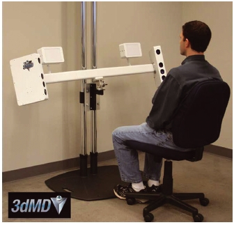
Figure 2.2 Multiple camera system with structured light patterns to obtain a three- dimensional image. The image shown is the 3dMDface system (3dMD, Atlanta, GA, USA).
Structured light techniques
The structured light technique is another broad category of systems used for capturing 3D information based on triangulation principles. Normally, a projector shines a pattern of “structured” light (which may be composed of elliptical patterns, random texture, maps, etc.) onto a targeted surface to be scanned. When the light illuminates the surface, the light pattern distorts and bends. A system of cameras at a known distance captures the reflected and distorted pattern under an angle and translates the information into 3D coordinates. An example is shown in Figure 2.2.
Single-camera systems
Tuncay and co- workers developed a series of 25 different high- density structured light patterns and evaluated the system on a mannequin made up of a skull embedded in latex. The imaging system consisted of a black and white charge- coupled device camera and a monochrome liquid crystal display projector connected to a Macintosh computer. The cameras and projectors were positioned at 30 degree angles to each other, and the mannequin was rotated on a turntable at 10 degree increments over 180 degrees. The technique produced satisfactory results, but this accuracy was reduced when a human face was utilized.35,36
Enciso and co – workers in 2003 also reported on a single – camera system, consisting of a slide projector, a digital camera, and a calibration pattern.37 Using a digitizer for validation purposes, landmarks were plotted and the linear distances calculated between real physical distances and image- produced distances.37 The errors found ranged between 0.48 and 1.55 mm.
Two or more camera systems
Moiré fringe patterns
One of the earliest methods using the “structured” light technique utilized “moir é” fringe patterns and was first described in 1970.38 Moir é topography imaging is a contour- mapping technique that involves positioning a “grating” close to an object and observing its shadow on the object through the grating. The resultant “moir é” fringes correspond to a contour line system of the object under certain conditions.
One study reported the use of a similar technique/>
Stay updated, free dental videos. Join our Telegram channel
VIDEdental - Online dental courses


