2: Surgery of the posterior mandible

Surgery of the posterior mandible

image Additional illustrations can be found on the companion website at www.blockdentalimplantsurgery.com

Placement of implants in the posterior mandible

General considerations

All patients evaluated for the placement of implants require a thorough medical and dental history. The medical health of the patient may reveal systemic problems that can affect wound healing. The dental history of the patient provides critical information about patients who have lost teeth and retained other teeth. Why did they lose their teeth? Did they have severe periodontal disease secondary to poor oral hygiene, parafunctional habits, or pathogenic bacteria? Did they have chronic problems with a tooth with multiple endodontic procedures, periodontal grafts, and repeated restorative care? The answers to these questions relate to the preoperative assessment of the patient.

Patients with long-standing poor or marginal oral hygiene are not good candidates for implants. In a patient with chronic infections and patients who have not demonstrated good hygiene practice, the placement of implants is not recommended because of the increased incidence of implant infection. Patients must demonstrate an ability to clean and maintain their teeth. This criterion is vital for the long-term success of implants placed into the posterior mandible because poor oral hygiene can adversely affect the soft and hard tissues supporting endosseous implants. Patients with parafunctional habits can be treated with implant restorations. Special attention should be given to providing an occlusion that can protect the implants from excessive forces. Molar crowns may be decreased in dimension to allow for development of embrasures and to encourage access to the lingual surfaces for cleaning. Crown margins are typically kept at the gingival margin on the lingual and in the interdental area, and between ½ to 1.0 mm subgingival on the labial surface for esthetics. However, many clinicians prefer crown abutment margins at the gingival margin or even ½ mm supragingival.

Consultation with restorative dentists reveals their understanding of patients’ desires and motivation. The restorative dentist, who likely has followed the patient for years, can help the surgeon gain a better understanding of the characteristics of the patient. Patients who smoke cigarettes or consume alcohol daily are advised that they are not ideal candidates for dental implant restorations. They are counseled to eliminate these habits and often are sent to their internists to confirm adequate clotting times, liver function, and the absence of other systemic problems related to these habits. If implant therapy is performed, they are warned that they have a greater risk of implant failure or bone loss than nonsmoking patients.

The most common tooth to replace with an implant is the first molar secondary to fracture, bone loss, or caries. Other common posterior mandibular sites include the fractured premolar, the need to remove the first and second molars, or previous loss of the posterior dentition with ridge resorption. These patients all desire a fixed rather than a removable solution to restore their missing teeth. Patients do not like and do not wear removable partial dentures without chronic complaints.

Treatment planning and diagnosis

After the medical and dental histories reveal that the patient is an acceptable candidate for implant surgery, the treatment planning and diagnostic sequence of events can be initiated.

Physical examination

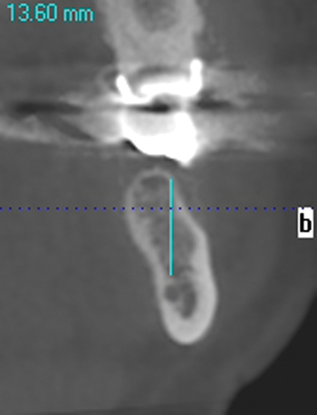
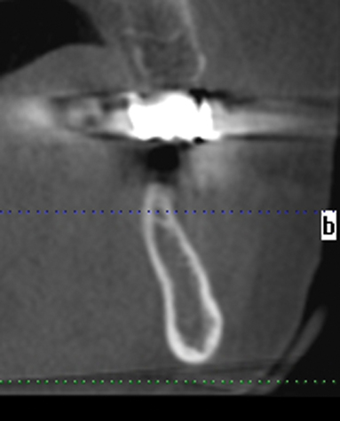
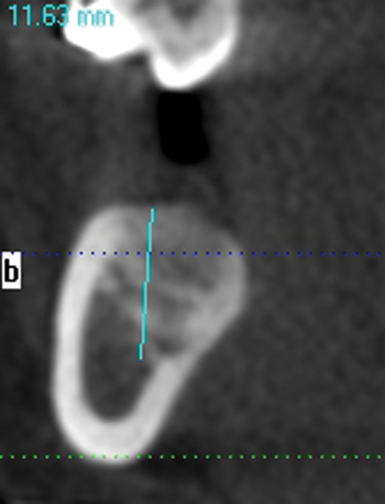
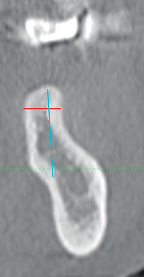
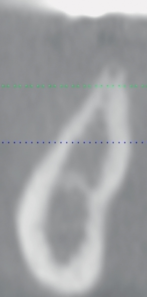
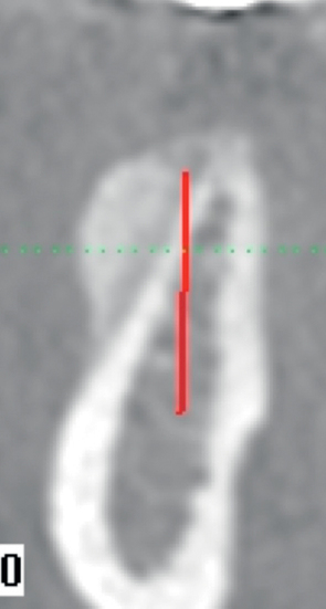
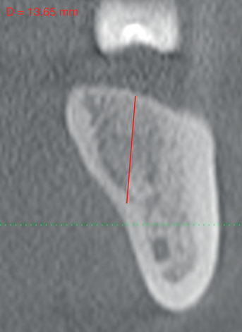
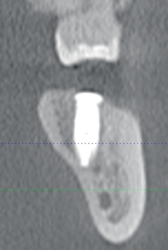
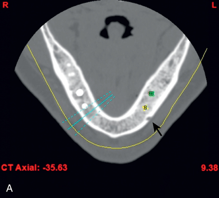
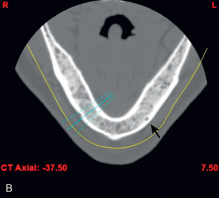
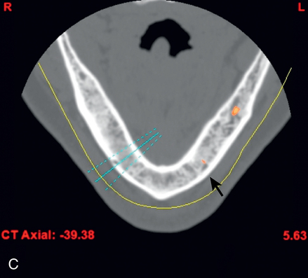
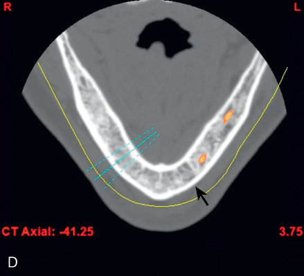
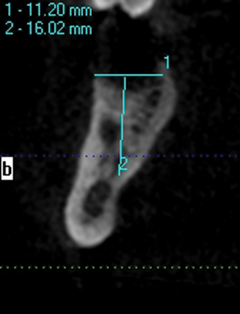
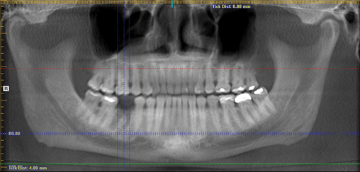
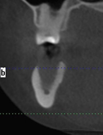
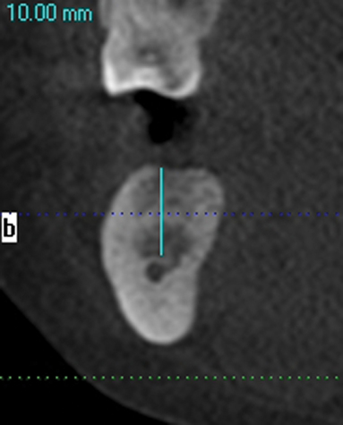
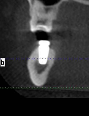
A screening radiograph is obtained. A cone-beam scan with cross-sections is most useful to identify the width of the crest, the sloping of the crest, the location of the internal oblique ridge, and the distance to the inferior alveolar nerve (Figure 2-1). The cone-beam scan is accurate to within 0.5 mm; thus, the magnification issues with panoramic radiographs are not a problem. Traditional panoramic or periapical images simply do not provide the accuracy or cross-sectional views as well as a cone-beam scan. After the radiograph is reviewed, an oral examination is performed to document the following:

The use of a cone-beam scanner for imaging the posterior mandible before placing dental implants is becoming increasingly more popular because of the accuracy of the image and the critical information visible for planning. Computed tomography (CT) accurately reveals the location of the inferior alveolar canal. The distance from the crest to the nerve is seen. The location of the nerve facial-lingually, and its distance from the inferior border is easily seen. The shape of the alveolar crest is visualized in the cross-section reconstructions. Lines can be drawn on the images to simulate planned implant placement regarding emergence to the opposing working, palatal cusp of the maxillary teeth. All of these observations lead the surgeon to plan the length of the implant, the diameter of the implant, the intended angulation of the implant, and the need for ridge augmentation. The planned placement can be correlated to the slopes of the facial or lingual cortical plates providing a simple reference for implant angulation during implant placement surgery.

The axial images can be scrolled vertically to observe the course of the nerve as it loops anteriorly, if at all, and how it exits the mandible at the mental foramen. This distance can be accurately measured on the scan, which can then be used to plan implant placement. The CT scan’s DICOM data set can be transferred to a computer for virtual implant placement, simulating the surgery necessary to be performed. By using all technologies available, the chance of damage to the nerve is decreased, the chance of placing an implant dehiscing through the bone is decreased, and the angulation of the implant can be determined to optimize axial loads on the implant.

The relationship of the bone to the proposed restoration must be established before the implants are placed. Ideally, the implants should be placed under the surface of the tooth that is receiving the forces of mastication (Figure 2-2). For the posterior mandibular teeth, these are the fossae and buccal cusps. The surgeon should gain an understanding of the relationship of the available bone to the working cusps of the teeth to be restored. With an understanding of the functional loading relationship of implants and bone, the implants can be placed to withstand the forces of chewing. After the posterior mandibular teeth have been extracted, it is common to lose a portion of the thickness of the facial bone. Implants placed too far lingually result in a lingualized occlusion or buccal cusp cantilevers, which may cause abutment fracture after loading. The surgeon may need to graft, restoring buccal deficiencies, to allow placement of implants under the cusps or fossae. Adequate thickness of facial bone allows for a mechanically stable restoration. If grafting is not absolutely indicated because of near-adequate bone position, the implant-supported restoration may be fabricated with a smaller occlusal table to distribute the forces of chewing evenly. To assess whether the patient has a satisfactory amount of bone for the placement of implants into a proper location, a diagnostic setup of the planned restoration may be necessary.

Stent fabrication

For placement of more than one implant in an arch, it is valuable for the surgeon to know where the final location of the teeth will be located. An analogy is knowing where you are going when you get into your car. The location of the final planned restoration can be determined by using a current removable denture, a tooth setup using wax or denture teeth, or a virtual plan using CT planning software. The surgeon needs to locate the implants within the corpus of the teeth, avoiding the embrasures and placing the teeth within 1.5 to 2 mm from the adjacent teeth to allow for optimal emergence profiles of the teeth and normal hygiene efforts by the patient.

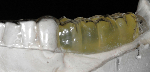
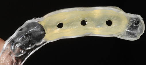
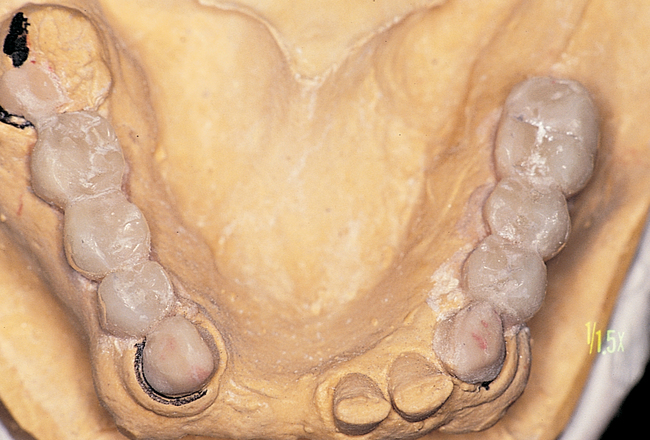
Often the patient has been wearing a removable prosthesis, either as a temporary or a long-term device. If the occlusion is adequate and the teeth approximate the planned anatomic form for the final crowns, the removable prosthesis can be used as a template for the stent. Two impressions are taken, one with and one without the removable prosthesis in the mouth. A thin, plastic vacuum form is made over the stone model of the prosthesis in the mouth. It is removed and trimmed to fit onto the model with remaining dentition only. If the clinician requires a more rigid stent, acrylic can be placed into the hollow cavities of the teeth, as shown in Figure 2-3.

Diagnostic models can be mounted on an anatomic articulator, and teeth can be set or waxed on the models. An acrylic copy of the teeth with an acrylic overlay of the remaining dentition can be made in the laboratory. The implant locations can be determined, and pilot holes can be made through the acrylic. A thin, clear vacuum form also can be made over the model, allowing visualization of the location of the teeth and their orientation to the residual mandible.

If the clinicians decide to use CT planning, a setup of teeth can be used to virtually place implants to determine implant angulation to avoid bone dehiscence and to avoid the inferior alveolar nerve. Either a single- or dual-scan method can be used. The single-scan method uses a radiopaque set of teeth created in a stent by filling the teeth locations of the clear vacuum form with a radiopaque material forming the teeth. These materials include clear resin combined with a radiopaque material such as barium sulfate–impregnated acrylic, composite resins, or gutta percha. If 30% or greater barium sulfate is used, the tooth form will be chalky; if less than 20% is used, the tooth form will lose some of its radiopaque properties. The use of radiopaque restorative materials is simple and predictable.

The dual-scan method uses a clear acrylic stent with flanges extending beyond the occlusal plane of the patient’s current metallic restorations. Fiduciary markers are placed into the flanges, and the clear acrylic stent with planned tooth forms intact is scanned out of the mouth and in the mouth. When the patient is scanned with the clear radiopaque stent in place, it is important to have the patient’s teeth slightly separated to avoid interferences from the opposing occlusion when virtually planning implant placement and their axial emergence.

With the CT scan, the resulting cross-sections locate the bone in relation to the planned restoration. The information revealed includes the height of bone superior to the inferior alveolar canal; the amount of bone available in relation to the working cusps and fossae of the planned crowns; and, depending on the quality of the scan, the quality of the bone in relation to trabecular bone density. Implants can be placed using virtual planning software, and if desired, a surgical guide stent can be fabricated.

Another option is to use the planned setup to place implant analogs within a master stone model. Using appropriate parts and metal sleeves that match the surgical guided kit, a model-based surgical guide stent can be fabricated from routine casts with implant analogs placed in the desired locations. This method relies on accurate knowledge of the bone anatomy, which will be discerned from the CT imaging of the planned restoration.

Different materials are used for grafting either the extraction socket or for ridge reconstruction. Graft materials undergo different rates of bone formation and resorption during the time from placement of the graft to implant placement; thus, accurate assessment of postgraft, preimplantation bone density and graft presence is best assessed with CT imaging with cross-sectional analysis. These images can be coupled with CT planning software to allow the practitioner first to identify bone and assess its density and then to choose the best implant length and width.

Determination of the number and size of implants

How many implants should be placed? What are the appropriate diameters and lengths of the implants? What type of implant is indicated? These questions must be answered before implants are selected and ordered for surgery. The type of implant (e.g., manufacturer and type [threaded, tapered, flared]) is decided after a consultation between the surgeon and restorative dentist. In the posterior mandible, the implant to be used may be determined based on the cortical bone thickness and the presence of abundant cancellous bone. The diameter of the implant is based on the diameter of the teeth to be restored, the width of available bone, and the philosophy of the restorative team. A single molar may be restored with one wide-diameter implant or two small-diameter implants, depending on available space. It is important to allow 3 mm between implants and 2 mm between the implants and natural teeth to promote bone healing, natural tooth form development, and access for oral hygiene maintenance. Two mm should be allowed from the apical aspect of the implant and the inferior alveolar canal. Closer placement of the implant to the canal may increase the risk of sensory nerve disturbance potentially from overdrilling caused by the triangular shape of the tips of most drills or bleeding within the marrow space.

Two premolar teeth can be restored with two implants of regular diameter or small diameter. Two molars can be restored with two wide-diameter implants. In general, the diameter of the implant should be smaller than the diameter of the tooth at the cement–enamel junction. Failure occurs when too few implants are placed and excessive forces of occlusion destroy the bone–implant interface. Implants can be attached to natural teeth, but this has been associated with fracture of the natural teeth or intrusion of the natural teeth.1 It is advised to restore implants with freestanding, implant-borne restorations, avoiding the attachment of implants to the natural teeth.

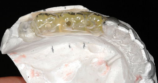
After the surgical plan has been developed and approved by the patient and restorative dentist, implant placement surgery can be performed. Appropriate consent forms must be signed. A surgical template is fabricated to allow the surgeon to place the implants in line with the fossa or working cusp and to avoid the embrasure spaces of the proposed restoration (Figure 2-4).

Surgical treatment

Placement of implants into adequate bone

This author recommends the use of an antibacterial solution to reduce the flora in the mouth. A chlorhexidine solution is used twice a day for 3 days before surgery to reduce the oral flora.2 Antibiotics are started the evening before surgery. At the time of surgery, a povidone–iodine solution is applied to the surgical site unless the patient has a known allergy to iodine.

Infiltrative anesthesia is used rather than inferior alveolar block anesthesia. Infiltrative anesthesia does not anesthetize the inferior alveolar nerve. However, the periosteal tissues are anesthetized using infiltrative anesthesia to provide patient comfort during surgery. The endosteal portion of bone does not have sensory innervation. If the drill gets close to the neurovascular bundle, the patient will feel discomfort and can alert the surgeon. This technique provides an additional safety measure for preventing inadvertent trauma to and permanent sensory impairment of the inferior alveolar nerve. The anesthetic solution is infiltrated lingually and labially, as well as directly over the alveolar crest. The local anesthetic solution is placed in a subperiosteal plane to perform a hydropic dissection of the tissues, allowing for relatively bloodless and efficient reflection of the tissues.

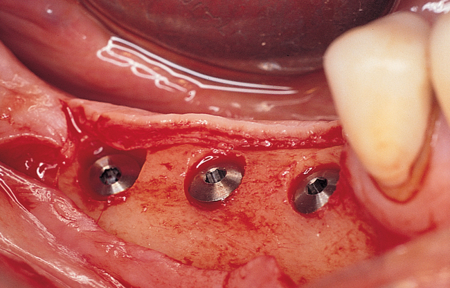
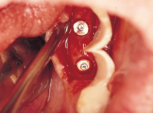
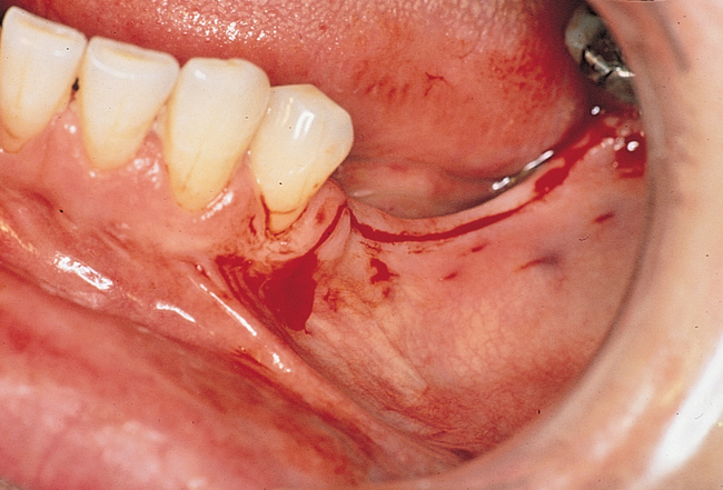
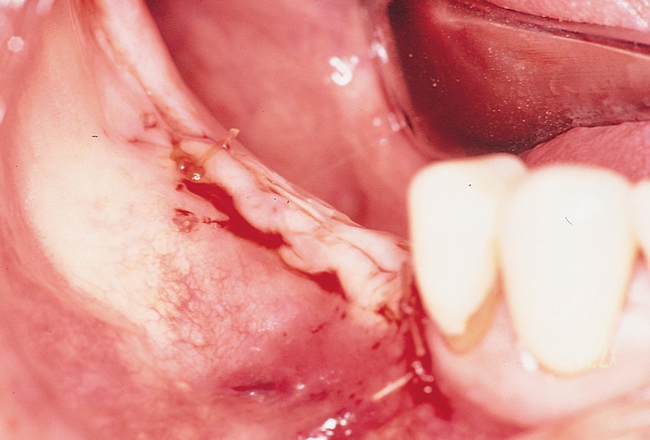
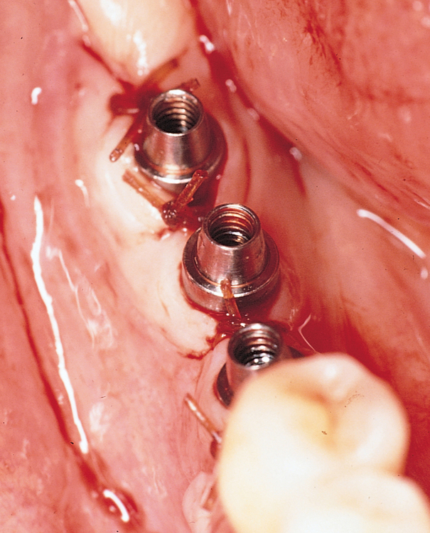
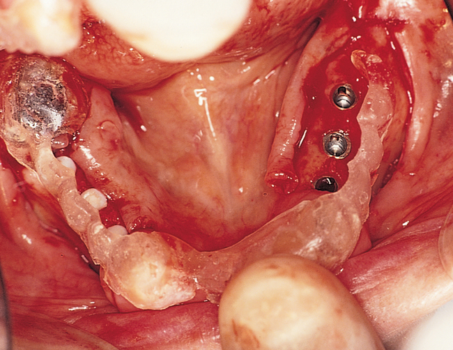
One incision design can be used in most cases. The incision bisects the often thin band of KG (Figure 2-5 and Figure 2-6) because an incision in the posterior mandible occasionally may break down. If breakdown occurs, KG is present on the lingual and labial aspects of the implant. If the incisions are made either lingually or labially to the KG and incision breakdown occurs, the KG will not be present on one aspect of the implant. Bisecting the KG also is used for a one-stage implant, whether the implant is so designed or when a one-stage technique is used intentionally to allow placement of a healing abutment into the implant or immediate provisionalization with a crown. Placement of the healing abutment eliminates the need for second-stage surgery, provides mature gingival tissue over the implant, decreases the number of surgical interventions and hence trauma to the gingiva, and prevents bone overgrowth over the implant.

The crestal incision is released vertically anterior and posterior to the planned posterior implant location. These vertical releases are made to the labial and lingual aspects and are placed approximately 1 to 1.5 mm away from the distal surface of the natural dentition. The benefits of avoiding elevation of the attached gingiva of the natural dentition are less postoperative discomfort and less chance of disturbing a healthy periodontal apparatus. The incisions also are easy to close without contaminating the periodontal ligament space of the adjacent natural dentition.

The incisions are made through the periosteum, and a full-thickness reflection is performed. Before the use of cone-beam cross-sectional imaging, it was important to reflect the periosteum inferiorly and anteriorly to identify the mental foramen and confirm the amount of bone available superior to the inferior alveolar canal. However, with the use of preoperative cone-beam evaluation, less tissue reflection is necessary because of the excellent knowledge of the patient’s anatomy.

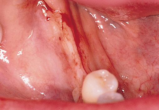
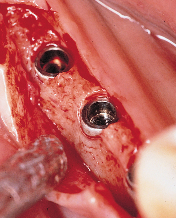
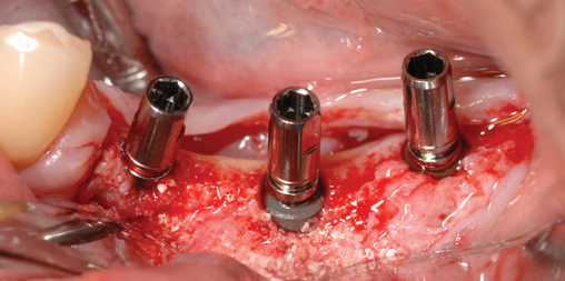
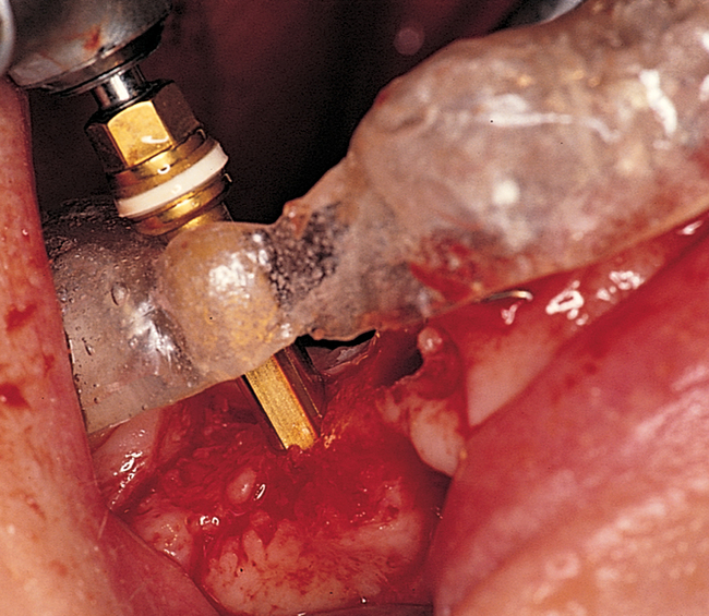
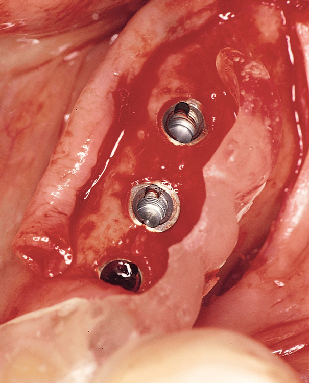
The specific locations for entry of the implants are marked with the surgical guide stent in place (Figure 2-7). These marks are made with a round bur. The stent is removed, and the locations of the drill sites are examined. The center of the implant site should allow the body of the implant to be at least 2 mm from the natural tooth. The surgeon should note the angulation of the roots of the adjacent teeth to avoid apical trauma to the natural tooth because tooth roots can be distal angled. A space of 3 mm should be maintained between adjacent implants to allow for ideal emergence of the crowns from the implants, maintenance of bone between the implants, and adequate healing of the bone to the implant. If the implants are placed too closely together, problems can develop, including difficulty placing the transfer copings and prosthetic abutments, difficulty creating an appropriate hygienic embrasure space, and crestal bone loss from inadequate bone adjacent to the implant.

The round bur is used first followed by the pilot drill. Most implant systems have a graduating-sized drill set. The pilot bur is taken to the expected depth of the implant chosen for placement. The surgeon acknowledges patient comfort and lack of excessive bleeding from the drill site to confirm that the drill is superior to the inferior alveolar canal. The drills are angled within the surgical stent to locate the implants opposite the working cusp of the opposite arch or, for cemented restorations, under the working cusp of the mandibular teeth. These positions are important because they locate the implants in the correct restorable location for the mandibular dentition. Parallel or guide pins are used to verify correct angulation. These pins are placed into the pilot hole. The patient is instructed to close very slowly to bring the parallel pin close to but not in contact with the maxillary teeth. The pin should be angled to meet the working cusps of the opposite arch, which are the maxillary palatal cusps. After this relationship has been verified, the drilling sequence can be continued. If angulation changes are necessary, the next-sized drills can be used to correct the angulation. This simple maneuver allows the surgeon to place the implants in a restorable position, which ensures ultimate success.

In the second molar region, the surgeon may perforate the lingual cortex within the mylohyoid concavity. This should be an expected event because the physical examination should have revealed this concavity. The implant chosen should be long enough to engage the lingual cortex without extending into the mylohyoid concavity. Preoperative cross-section cone-beam images can help determine specific implant lengths to engage but not excessively perforate the lingual cortex in the mylohyoid concavity.

After the drilling sequence has been completed, the implants are placed. The goal is to place the longest implant possible without trauma to the inferior alveolar nerve. The shoulder of the implants can be placed supracrestally, placed at the level of the crest, or countersunk 1 mm. This decision is based on the availability and quality of bone, the philosophy of the implant team, and the specific implant used. For a two-stage method, cover screws are placed and the incisions closed. For a one-stage system, a healing abutment is placed with the incision cinched around the healing abutment. If the implant is placed with the cover screw more than 1 mm supracrestally, incision breakdown may occur, exposing the implant cover screw. If this occurs, hygiene with topical chlorhexidine solution is recommended. The implant–gingiva interface should heal uneventfully, as has been well documented with one-stage implant systems and in this author’s experience.

Incision breakdown is proportional to the tension placed across the incision line. For most situations, a periosteal release is necessary to achieve a tension-free closure. Scissors can be used to cut the periosteum only, not the muscle or long buccal nerve. After the periosteum has been relieved, the incision can be closed without tension using atraumatic needles.

Placement of implants into single tooth sites with tooth removal

Typically, a patient seeks the extraction of a single tooth that is causing chronic pain, is refractory to periodontal treatment, or is nonrestorable secondary to fracture or caries. A simple algorithm can be used to decide on the timing of treatment. The three scenarios are depicted in Figure 2-8.

If there is minimal, less than 3 mm of intact apical bone present between the tooth apex and the inferior alveolar canal, it is recommended to remove the tooth and graft the socket, with implant placement delayed until the area has healed, typically by 4 months. This is a common finding for premolar locations.

If the tooth has extensive bone loss present, the tooth will need to be removed, granulation tissue debrided, and a graft placed with delayed implant placement after the bone has reformed. Typically, 4 months or more is required for sufficient bone density to form after the tooth was removed and the graft placed. Adequate bone formation is determined by radiographic evaluation.

If the tooth is “hot,” or has purulent drainage, or has very poor gingival health around the tooth to be removed but has labial and lingual bone present, the tooth is removed without grafting (Table 2-1). After the site becomes pain free and has no exudate, the implant is placed, typically 4 to 8 weeks after removal of the infected tooth. At this time, the implant site is similar to the freshly removed tooth but is not grossly infected. Often the implant can be placed into these sites with minimal flap reflection.

TABLE 2-1 

Treatment of the Extraction Site Depending on Clinical Presentation

Situation Minimal bone apical to tooth Presence of infection or “hot” tooth Greater than 3 mm labial bone loss or extensive intrasocket bone loss Minimal bone loss; no infection
Treatment Graft; delay placement until graft consolidates with bone Extract tooth; place implant 4–8 weeks if bone is present Graft; delay placement until graft consolidates with bone Place implant at time of tooth removal

image

If the tooth is not significantly painful, has no purulent exudate, has relatively healthy gingiva present, and has sufficient bone without extensive loss, the implant can be placed at the time of tooth removal. A healing abutment is placed to avoid a second-stage surgery for most of these sites and to provide mature, healed gingiva for efficient restorative care. This results in 4 months to restoration in contrast to 8 months when a graft-delayed implant placement is done.

Placement of implants immediately into mandibular molar sites

Placement of a dental implant into the socket immediately after removal of the tooth decreases the time to restoration and provides the patient with one surgical experience. Previous reports on immediate placement of implants into extraction sites in premolar, canine, and incisor locations have indicated excellent implant integration (range, 92%–98%).3 Walker4 reported excellent results with immediate placement of implants into molar sites, concluding that this is a viable procedure. He described a flapless approach with implant insertion torque as the measurement to predict implant success. With insertional torque values greater than 30 N-cm, the implant success rate was greater than 95%. He did not graft the sockets and did not obtain gingival closure over the bone defects. This author has modified the Walker protocol to include a conservative flap elevation to aid in tooth removal and cortical bone preservation, grafting the sockets, and partial coverage of the site with the gingiva that was adjacent to the extracted tooth.5

Inclusion criteria for immediate placement of the implant into a molar site includes a lack of exudate or purulence, presence of intact buccal and lingual cortical bone, a lack of active periapical pathology, and a healthy gingival margin. Sufficient vertical bone height above the inferior alveolar nerve canal and to the floor of the maxillary sinus is required for placement of the implant. Preoperative evaluation includes cone-beam CT to determine the location of the inferior alveolar nerve, the width of the bone, the presence of pathology at the molar site, and the vertical height of available bone to the mylohyoid ridge or the sinus floor. The scan shows divergence of the roots, which provides insight for proper site preparation to engage the maximum amount of bone for initial implant stability. The scan enables accurate planning to place the implant into the mesial or distal root socket, within the interseptal bone, or along the mesial or distal slope of the interseptal bone. In general, the implant should be placed centered between the adjacent teeth vertically oriented with the access screw angled to meet the working cusp of the opposite arch.

Implant selection. 

​A wide-diameter implant is chosen to engage the cortical bone in the inferior third of the site. Implants that are at least 5 mm diameter at their apical region can be used; however, implants that are 5.5 mm or greater in diameter seem to have higher insertion torque. Smaller diameter implants will not engage the bone because of the size of the tooth roots. The cone-beam scan is used to define the necessary implant length before tooth removal. The height of the buccal and lingual bone is noted. These landmarks are used to measure the distance to the inferior alveolar canal. The implant is chosen to avoid the canal. If the measured distance on cone-beam cross-section is 13.4 mm, then an 11- or 11.5-mm-long implant is chosen. If the distance is 11.9 mm, then a 10-mm-long implant is chosen. It is useful for the surgeon to have a bone reference for proper depth control, hence the use of either the lingual or buccal bone level as a physical reference point.

Surgical technique. 

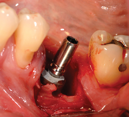
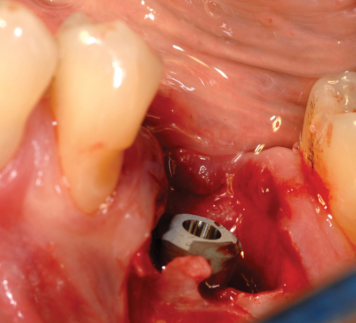
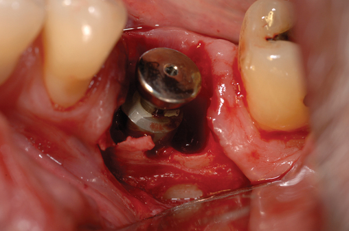
​The patient is prescribed chlorhexidine mouthwash to use two times each day for 3 days before surgery to decrease the oral flora.2 Local anesthesia is administered, including local infiltration and block anesthesia as necessary. A sulcular incision is made combined with vertical releasing incisions sparing the attached papilla of the adjacent teeth. If adjacent teeth are present mesial and distal to the molar to be removed, two vertical releasing incisions are made. If the tooth to be removed is the distal tooth, then only an anterior vertical release incision is made, sparing the papilla of the anterior tooth. The flap is reflected to visualize the tooth bone interface. The tooth is then removed (Figure 2-9). When removing the molar tooth, different techniques can be used. The surgeon must preserve the buccal and lingual bone and the interseptal bone. A piezosurgery periotome tip or small drills can be used. This separates the tooth from the labial bone, allowing its removal with minimal loss of bone. The tooth may need to be sectioned with preservation of the interseptal bone. If necessary, bone can be removed along the roots adjacent to the neighboring tooth, mesially and distally. This allows for removal of the tooth root while preserving the buccal or lingual bone. The roots are carefully removed. This may be the most difficult portion of the procedure (see Figure 2-9). After the tooth is removed, granulation tissue is debrided as necessary, and the site is gently irrigated. If epithelial downgrowth has occurred in the socket, this epithelium can be maintained intact; rotated superiorly, preserving its base; and used to cover the site after the implant has been placed. A round bur is used to create a definitive purchase in the desired location of the implant. The implant system’s drills are then used in succession, harvesting autogenous bone from the drills for later bone defect grafting, if present.

image
FIGURE 2-9  ​See Figure 2-8, D to E for additional radiographs of this patient. A, Pre-extraction view of fractured mandibular left first molar.

Stay updated, free dental videos. Join our Telegram channel

Jan 5, 2015 | Posted by in Implantology | Comments Off on 2: Surgery of the posterior mandible

VIDEdental - Online dental courses

Get VIDEdental app for watching clinical videos