Chapter 2
Implants and Implant Restorative Components
INTRODUCTION
Dental implant treatment requires a different, precise terminology that is unique to implant dentistry. Clinicians, dental laboratory technicians, and clinical and office staff must learn the proper terms for implants and implant restorative components to facilitate communication among the members of the implant team: surgeons, restorative dentists, dental laboratory technicians, third-party payers, patients, and implant manufacturers.
The implants and implant restorative components illustrated in this textbook were manufactured by Implant Innovations, Inc.®, Palm Beach Gardens, Florida and Nobel Biocare, Yorba Linda, California.
IMPLANTS
Dental implants are the components that are placed into patients’ bone with the intent of achieving osseointegration. Osseointegration was originally defined by Brånemark as “… the direct structural and functional connection between ordered, living bone and the surface of a load carrying implant.” Surgical placement of endosseous implants initiates a complex series of biologic events associated with wound healing: inflammation, proliferation, and maturation (Zoldos and Kent 1995).
Healing of bone and soft tissue around endosseous implants is a dynamic process; it is the result of numerous factors, among them: surgical, atraumatic technique; osteotomy design; host immune system; macroscopic and microscopic design features of dental implants; fit of implants into the osteotomies; wound dehiscence; and loading protocols. For optimal performance in humans, dental implants should have appropriate mechanical strength, biocompatibility, and biostability (Cook et al. 1987). Further discussion of the biology of osseointegration is beyond the scope of this textbook. The reader is referred to other sources for further information.
Clinicians may choose implants from any number of implant manufacturers. Implants may be made from various materials, but commercially pure (cp) titanium or titanium alloy have enjoyed extraordinary clinical results. Dental implants come in various sized diameters and lengths, with various macroscopic thread designs, surface treatments, and implant/abutment connections. Where possible, catalog numbers, implant, and restorative components will refer to products made by the respective dental implant manufacturers.
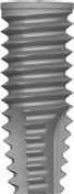
Figure 2.1 Lateral view of threaded Biomet 3i, 4.0 × 11.5 mm OSSEOTITE external hex implant (OSS411).
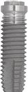
Figure 2.2 Lateral view of threaded Biomet 3i, 4.0 × 11.5 mm OSSEOTITE® CERTAIN implant (IOSS411). This implant features an internal implant/abutment connection.
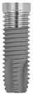
Dental implants manufactured by Biomet 3i, Palm Beach Gardens, Florida, were made with threaded external surfaces for tapered and cylindrical implant designs (Figures 2.1 and 2.2). The original external hex implant design (OSSEOTITE®) consisted of a six-sided hex, 0.7 mm tall; flat-to-flat hex surface measurements of 2.7 mm; and restorative platforms that measured 4.1 mm (Figures 2.3 and 2.4). Biomet 3i™’s internal implant/abutment connection implants were called the Certain® Implant System.
Dental implants are available in multiple diameters: 3.25, 4.0, 5.0, and 6.0 mm (Figures 2.5–2.8). This particular series of implants have dual acid etched surfaces. More recent design changes feature implant restorative platforms that are platform switched: the diameters of the implants are one size larger than the diameters of the implant restorative platforms (Figures 2.9 and 2.10). These implants are manufactured by Biomet 3i under the name Prevail.
Figure 2.3 Lateral view of OSSEOTITE® external hex implant. Vertical measurement of external hex measured 0.7 mm (4.1 mm restorative platform left; 5.0 mm restorative platform right).
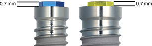
Figure 2.4 Occlusal view of premachined abutment with a 4.1 mm restorative platform. Flat surface to flat surface of the hex measures 2.7 mm. Microstops (Gold Standard ZR™) have been machined into the corners of the hex in UCLA Abutments and GingiHue™ Posts.
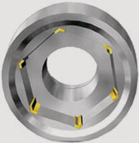
Figure 2.5 Lateral view of 3.25 mm diameter internal connection implant. This implant expanded to a 3.4 mm restorative platform (IFNT3213).
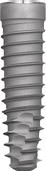
Figure 2.6 Lateral view of 4.0 mm diameter internal connection implant. This implant expands to a 4.1 mm restorative platform (IFNT411).
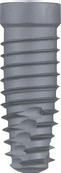
Figure 2.7 Lateral view of 5.0 mm diameter internal connection implant (IFNT511).
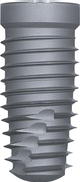
Figure 2.8 Lateral view of 6.0 mm diameter internal connection implant (IFNT611). This implant may best be used in patients with wide alveolar ridges or immediately post extraction of molar teeth.
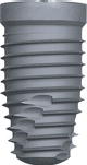
Figure 2.9 Lateral view of a Biomet 3i implant (IIOS5413) with platform switching machined into the restorative platform.
Dental implants manufactured by Nobel Biocare, Yorba Linda, CA, are also made with threaded external surfaces for tapered and cylindrical implant designs. Nobel Speedy™ is a slightly tapered implant with a slightly more pronounced apical taper that allows for underpreparation of osteotomies (Figure 2.11). NobelActive™ is the newest dental implant manufactured by Nobel Biocare (Figure 2.12). It is manufactured with hybrid design features that include a slightly tapered design, although parallel wall drilling protocols are recommended for implant placement. This implant was designed for experienced surgeons and delivers high initial implant stability, especially in sockets and soft bone.
Figure 2.10 Occlusal image of the restorative platform of the Biomet 3i implant machined with platform switching (IIOS5413) illustrated in Figure 2.9. The outer circumference (gray area) of this implant is approximately 4.8 mm in diameter; the restorative platform is 4.1 mm in diameter (blue area). Even though the body of the implant is approximately 5 mm, 4.1 mm restorative components must be used.
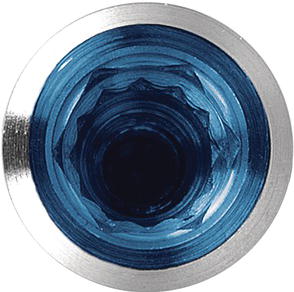
Figure 2.11 Lateral view of NobelSpeedy™ Replace implant.
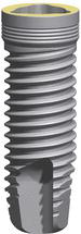
Figure 2.12 Lateral view of NobelActive™ implant (left);occlusal view of internal conical connection for NobelActive™ implant with platform shift feature machined into the implant restorative platform (right).
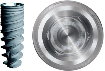
Figure 2.13 Lateral view of Replace™ Select straight implant.
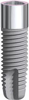
Table 2.1 Implant lengths and catalog numbers (4 mm diameter) for OSSEOTITE® Certain® implants.
| Length (mm) | OSSEOTITE® Certain™ implants | OSSEOTITE® Certain™ NT implants |
| 8.5 | IOSS485 | INT485 |
| 10.0 | IOSS410 | INT410 |
| 11.5 | IOSS411 | INT411 |
| 13.0 | IOSS413 | INT413 |
| 15.0 | IOSS415 | INT415 |
| 18.0 | IOSS418 | N/A |
| 20.0 | IOSS420 | N/A |
Table 2.2 Implant lengths and catalog numbers (4 mm diameter) for Brånemark System™ Mk III Groovy RP and Mk III TiUnite® implants.
| Length (mm) | Mk III Groovy RP | Mk III TiUnite® |
| 8.5 | 32126 | 28919 |
| 10 | 32127 | 28920 |
| 11.5 | 32128 | 28921 |
| 13 | 32129 | 28922 |
| 15 | 32130 | 28923 |
| 18 | 32131 | 28924 |
NobelReplace™ and Replace Select™ were designed to deliver optimal initial stability in soft and hard bones (Figure 2.13). These implants are manufactured with tapered and straight implant designs, with and without textured collars. NobelReplace™ and Replace Select™ feature internal trichannel implant/abutment connections.
Increasing the lengths of dental implants increases the amount of bone in contact with dental implants. Increased lengths may also have a positive impact on insertion torque and implant primary stability. Dental implants are generally made in increments of approximately 2 mm (Tables 2.1 and 2.2).
IMPLANT/ABUTMENT CONNECTIONS
Osseointegration of dental implants has proven to be predictable in clinical practice (Adell et al. 1981; Davarpanah 2001). The original design for implant restorations per the Brånemark protocol called for screw-retained prostheses. It was not unusual for screw-retained implant restorations to become loose secondary to screw loosening or screw fracture (Jemt et al. 1991; McGlumphy and Huseyin 1995). However, there are more recent reports that demonstrated decreased numbers of screw failures for implant-retained restorations (Zarb and Schmitt 1990; Levine et al. 1999; Nissan and others 2011).
Mollersten and others reported on the effect of implant/abutment joints on the strength and failure modes of implants from several different implant manufacturers (Mollersten et al. 1997). They reported that the strength of the implant/abutment connections varied significantly depending on the length or depth of the connections. Low joint depths or lengths (<2.3 mm) were correlated with failures at lower forces; large/thicker joint depths (>5 mm) were correlated (r = 0.959) with failures at higher levels. The lowest failure was measured at 138 N for a connection that was 0.8 mm long. The highest failure was recorded at 693 N for a connection that measured 6.0 mm in length.
In a photoelastic stress analysis of external versus internal abutment connections, Asvanund and Morgano (2011) compared the load transfer characteristics of a complete arch prosthesis supported by four implants with internal and external implant/abutment connections (Replace Select, Nobel Biocare). They applied loads to the prostheses in three positions. With the four-point load, no stress differences occurred between the external implant/abutment and internal implant/abutment connections at the connection level and at the apical level. With the two-point anterior load, the internal implant/abutment connection resulted in lower stresses at the connection level in the loaded and nonloaded areas. With the two-point lateral load, the internal implant/abutment connection resulted in lower stresses at the connection level at the nonloaded area. They concluded that when the implants were loaded off-center, the internal implant/abutment connection produced less stress when compared with the external implant/abutment connections.
External Implant/Abutment Connections
The original Brånemark protocol called for the placement of external hexed implants to support full-arch restorations for patients with edentulous jaws. The implants were rigidly splinted together with metal castings attached to implant/abutments with retaining screws. The external hex of the original implants was designed to drive implants into their respective osteotomies (Beaty 1994). It was not designed as an antirotation component for single-unit implant restorations. The external hex measured 0.7 mm in height and was not designed to withstand masticatory forces on single, screw-retained crowns (Jemt and Pettersson 1993; Binon 1995).
Implant manufacturers compensated for this design by changing the type of screw used for attaching abutments to implants – geometry, height and surface area; improved machining between implants and implant restorative components; and application of appropriate torque to the screws (Finger et al. 2003). The goals of any modification in the original external hex designs were to improve the stability of the implant/abutment connection on a long-term basis. According to Finger and Castellon, there were at least 20 different implant/abutment connection designs that have been approved by the Food and Drug Administration for sale in the United States (Finger et al. 2003).
Clinical success with external hexed implants is dependent on precise machining between implants and implant restorative components, and the stability of screw joints. Screw joints are found wherever two implant components are tightened or held in place by screws. The screw joint will fail (the screw will loosen) if outside forces are greater than the ability of the screw to keep the units tight. Forces attempting to disengage the screw joint are called joint separating forces. Those forces attempting to keep the joint together are called clamping forces. There are two primary factors involved in maintaining screw joints: maximum clamping forces and minimal separation forces.
In external hex implant systems, screw joints include abutments, abutment screws, and implants. As the abutment screw is tightened or torqued, a compressive clamping force is generated between the abutment and implant. An equal, but opposite tensile force is generated between the abutment screw and abutment. This force is referred to as the joint preload or preload (Sakaguchi et al. 1994). Schulte (1994) measured the external hex dimensions of six implant systems and obtained the ranges and coefficients of variance. Smaller ranges and variances suggested more accurate machining and better quality control. The ranges for the widths of the external hexes for all companies were 0.00030 for 3i to 0.00140 for Nobelpharma. Schulte concluded that there were differences in quality control among the various implant systems as determined by the external hex measurements but that larger sample sizes and different batches may make a difference in the results.
Cardoso and others (2012) evaluated the variation in removal torque of abutment screws after repeated tightening and loosening cycles, as might occur in clinical practice with multiple screws loosening and retightening. They reported that removal torque values tended to decrease as the number of insertion/removal cycles increased for both groups (hexed and nonhexed abutments). Comparisons between groups showed no statistical difference. They also reported that there was no significant difference between the mean values of the last 5 cycles and the 11th cycle. Within the limitations of the in vitro study, Cardoso and others concluded that (1) repeated insertion/removal cycles promoted gradual reduction in the removal torque of screws, (2) replacing abutment screws (titanium) with new ones after ten cycles did not increase the resistance to loosening, and (3) removal of the hexagon from the abutment base had no effect on the removal torque of the screws.
Torque may be defined as a measurable means of developing tension in a screw joint. Tightening involves the application of torque. Every screw design has a specific preload/torque relationship depending on the material used in the screw and the design of the screw head.
Preload is induced into abutment screws when screws are torqued during tightening. Preload stabilizes the implant/abutment connection by producing a clamping force between the screw head and its seat inside the abutment. As torque is applied to the abutment screw, the abutment screw actually elongates, which places the screw shank and screw threads in tension. The elastic recovery of the screw actually creates the clamping force between the abutment and implant. This concept is of great clinical significance because the resistance of the abutment to displacement or screw joint failure is a function of preload or the clamping forces between the abutment and implant (Figure 2.14).
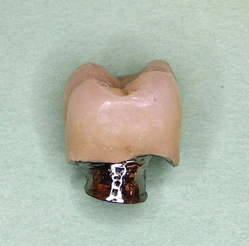
Within the last several years, implant manufacturers have introduced prefabricated or machined abutments that were designed for use with cement-retained crowns (Keith et al. 1999). Cement-retained crowns have several advantages over screw-retained crowns; the most important is that there is no longer a need to develop a screw access opening in the occlusal or facial surface of the implant crown restoration (Figures 2.15 and 2.16). However, cement-retained crowns are not as retrievable as screw-retained crowns in the event that the abutment and/or crown have to be repaired (Figures 2.17 and 2.18). One survey of commercial dental laboratories suggested that the number of screw-retained restorations was decreasing (Marinbach 1996).
Figure 2.14 Clinical photograph of a broken abutment screw inside an external hexed implant.
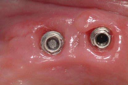
Figure 2.15 Facial view of an implant cement-retained crown replacing the maxillary left lateral incisor.
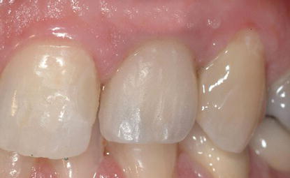
Figure 2.16 Occlusal view of the implant cement-retained crown in Figure 2.15. Note the lack of a screw access opening on the palatal surface.
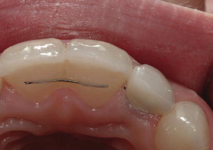
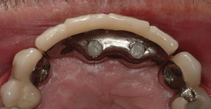
Figure 2.17 Facial view of an implant screw-retained fixed partial denture (FPD) (inserted 1992) replacing the maxillary incisors.
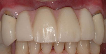
Figure 2.18 Occlusal view of the implant screw-retained FPD in Figure 2.17. Note the screw access openings provide access to the abutment screws without interfering with the facial aesthetics of the prosthesis.
One of the keys to successful long-term implant restorations is the stability of the implant/abutment connection. Rodkey (1977) pointed out that the type of finish on screws could have a significant effect on the tension induced by a given torque. Implant manufacturers have altered the materials in the screws as well as the surface of abutment screws in an attempt to prevent or minimize screw loosening (Porter and Robb 1998; Robb and Porter 1998; Steri-Oss 1998). Martin et al. (2001) tested the rotational angles in implant/abutment connections with various abutment screws and preloads. They found that the abutment screws with enhanced surfaces reduced the coefficient of friction and produced greater rotational angles and preload values than screws made from conventional gold and titanium alloys.
In review, external implant/abutment connections have proven to be successful in clinical use (Eckert and Wollan 1998; Drago 2003). This connection has a long, successful history in clinical implant dentistry and is still a viable choice for clinicians.
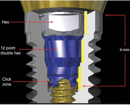
Figure 2.19 Cross-sectional diagram of OSSEOTITE® Certain® implant illustrating 4 mm length of internal implant/abutment connection.
Internal Implant/Abutment Connections
One of the first internal implant/abutment connections was designed with a 1.7 mm internal hex below a 0.5 mm wide 45° bevel (Niznick 1983). This system was designed to distribute masticatory forces deeper within the implant, which would protect the abutment screw from excess occlusal loading. This internal implant/abutment connection provided greater strength to the implant/abutment joint (Niznick 1991) when compared to the strengths of external hex implant/abutment connections.
The OSSEOTITE® Certain® implant internal connection is 4 mm long (Figure 2.19). These connections also feature intimate contact along a significant length of the connection that provides increased lateral stability to the implant/abutment connection (Niznick 1991; Mollersten et al. 1997).
Laboratory testing has demonstrated that internal connec tion implant/abutment connections are stronger than external hex implant/abutment connections (Implant Innovations 2003). The testing was conducted by placing 30° static loads to abutments connected to their respective implants with abutment screws torqued to a known level of preload. The internal connection implant/abutment connections failed at 767 N cm of force. The external hex implant/abutment connections failed at 648 N cm. It is important to note that the abutment screw for the internal connection was a hexed abutment screw tightened to 20 N cm of preload. The external implant/abutment connection was maintained with square abutment screws torqued to 35 N cm of preload (Table 2.3).
Nobel Biocare has identified four product characteristics that complement patient-related factors and the selection of appropriate treatment protocols (Geiselhoringer 2012):
Kim and others (2011) reported on the results of a laboratory study where they studied variations in total lengths of abutment/implant connections as functions of applied tightening torque in both internal and external hexed implant systems. The researchers used five different implant/abutment connections (external hex, external butt joint + two-piece abutment; internal hexagon + two-piece abutment; internal hexagon + one-piece abutment; internal octagon + two-piece abutment; internal octagon + one-piece abutment). All abutments of each group were assembled and tightened with the corresponding implants with a digital torque gauge. The total lengths of the implant/abutment connection samples were measured at each torque (5, 10, 30 N cm, and repeated 30 N cm with 10 min intervals) by an electronic digital micrometer. The settling values were calculated by changes between the total lengths of implant/abutment samples. All groups developed settling with repeated tightening. The Internal-H2 group showed markedly higher settling for all instances of tightening torque; the external hex group changed the least. Statistically significant differences were found in settling values between the groups, and statistically significant increases were observed within each group at different tightening torques (P < 0.05). After the second tightening of 30 N cm, repeated tightening showed almost constant settling values. Kim and others concluded that to minimize the settling effect, abutment screws should be retightened at least twice at 30 N cm torque at 10 min intervals in all laboratory and clinical procedures.
Table 2.3 Force required to break implant/abutment connections.
| Internal connection – abutment screw torqued to 35 N cm | 774.7 N cm |
| Internal connection – abutment screw torqued to 20 N cm | 767.1 N cm |
| External connection – abutment screw torqued to 35 N cm | 648.4 N cm |
| Internal connection – no screw | 519.9 N cm |
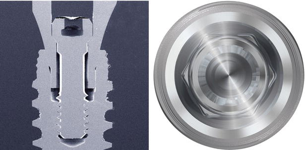
Figure 2.20 The NobelActive conical abutment connection’s radial design distributes the forces deep within the core of the implant. Cross section of the internal connection (left); implant restorative platform (right).
The OSSEOTITE® Certain® implant system features several design changes that have facilitated predictable implant restorative treatment. The hexed abutment screw measures 1.95 mm from the occlusal aspect of the screw to the screw seating surface (Figure 2.21). This allows clinicians and laboratory technicians great flexibility in abutment preparation, decreasing the risk of abutment wall fracture or fenestration (Figure 2.22). The long implant/abutment connection allows clinicians to positively seat impression copings and abutments into their appropriate positions (Figure 2.23). This internal connection also features audible and tactile feedback (QuickSeat™ Connection) during abutment and impression coping insertion by way of click associated with flexure of fingers at the apical ends of the restorative components (Figure 2.24). The connection also features a 6/12 internal connection that has a hex and 12-point double hex. The hex serves two functions: it engages the driver tip for mountless delivery during implant placement, and it provides antirotation for all straight abutments. The 12-point double hex provides rotational positioning every 30° for the 15° Pre-angled GingiHue™ Post (Figure 2.25).
Figure 2.21 Lateral view of an abutment screw (IUNIHG) for the OSSEOTITE® Certain® implant illustrating the length of hex abutment screw.
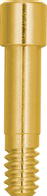
Figure 2.22 Cross section of GingiHue® Post (OSSEOTITE® Certain® Implant System) demonstrating sufficient axial wall thickness for preparation.
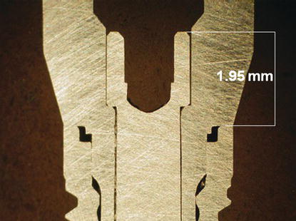
Figure 2.23 Pickup implant impression coping (OSSEOTITE® Certain® Implant System, IIIC12). Thisimpression coping features a 4 mm connection that allows clinicians to positively seat the coping into the implant with little risk of inaccurate seating.
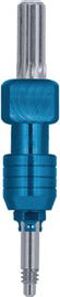
Figure 2.24 Pickup implant impression coping (OSSEOTITE® Certain® Implant System, IIIC12) with four fingers at the apical end of the coping that provide an audible click when seated into an implant or implant analog.
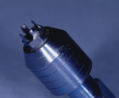
Figure 2.25 Occlusal view of OSSEOTITE® Certain® Implant System internal connection. The 12-point double hex is apical to the hex at the occlusal portion of the implant.
The success of conventional prosthodontic treatment is dependent on the accuracy of transferring tooth and/or implant positions intraorally to impressions and ultimately to definitive master casts. Implant impressions can be accomplished with one of two techniques: transfer or pickup. Each technique requires the use of specifically shaped impression copings. The transfer implant impression technique, also referred to as a closed-tray technique, uses conically shaped impression copings that remain on the implants after the impression is removed from the mouth. This is similar to the procedures used in traditional fixed prosthodontics. The pickup implant impression technique, also referred to as open-tray technique, uses impression copings that must be unscrewed from the implants after the impression material has polymerized because these copings were designed with undercut areas and the copings remain inside the impression. They must be unscrewed prior to removal; access to the tops of the screws has been maintained through windows cut into the impression trays.
Accurate master casts can be fabricated with either technique (Loos 1986; Sutherland and Hallam 1990; Taylor and Bergman 1990). Lee and others (2008) reviewed 17 articles on whether splinting impression copings (pickup technique) together affected accuracy of the impressions. Seven papers advocated splinting versus nonsplinting impression copings; three reported that unsplinted impression copings yielded better results, while seven authors reported no differences in accuracy. In the same review article by Lee and others regarding accuracy comparisons between unsplinted transfer (closed-tray) and pickup (open-tray) impression protocols, five reported that the pickup (open-tray) method was more accurate, two found the opposite to be true, and seven found no differences in accuracy between the two groups.
Vigolo et al. (2004) studied the accuracy of implant impression techniques with the OSSEOTITE® Certain® implant system. They found that improved accuracy of the master cast was achieved when the square, pickup implant impression copings were joined together with autopolymerizing acrylic resin for multiple, splinted implant restorations.
HEALING ABUTMENTS
EP® Healing Abutments
Originally, abutments and gold cylinders were designed for use in edentulous patients. As implant treatment evolved to include partially edentulous patients, clinicians became frustrated with the limitations of the original edentulous components to provide aesthetic, natural-looking implant restorations (Jansen 1995). Most implant components were 4–5 mm in diameter; natural teeth are present in multiple sizes; many teeth were larger than the components. A maxillary central incisor generally has a cemento-enamel junction (CEJ) diameter between 6 and 8 mm (Linek 1949). With the original edentulous components, there were several millimeters difference in size between the implant components and maxillary central incisors. Laboratory technicians were asked to make implant restorations with natural contours and, in many cases, had to add ridge laps to the restorations to mimic the contours of the adjacent natural teeth. The ridge laps resulted in nonphysiologic contours that were etiologic factors in peri-implant soft tissue inflammation (Figure 2.26).
Figure 2.26 PFM implant crown designed with a significant buccal ridge lap for aesthetic reasons. Unfortunately, the ridge lap resulted in a large concavity that the patient would not be able to clean effectively.
An implant/abutment emergence profile similar to that of a natural tooth is required to support and contour the peri-implant soft tissues (Saadoun 1995). The cylindrical shapes of implants must be changed to more anatomically correct cross sections by the time the implant restorations reach the gingival margins, reflecting the root structure of the teeth being replaced (Weisgold et al. 1997). Lazzara considered dimensions and contours of implant-retained crown restorations and the stability of the gingival margins surrounding implant restorations to be the two primary concerns in assuring durable aesthetics in implant restorations (Lazzara 1993).
EP® Healing Abutments were designed as part of Biomet 3i’s Emergence Profile System® to guide soft tissue healing after implant placement in single-stage surgical protocols or after implants had been uncovered in two-stage surgical protocols (Implant Innovations 1993) (Figures 2.27–2.29). They are available for all implant restorative platforms. EP® Healing Abutments were designed with collar heights between 2 and 8 mm and 3.4, 4.1, 5, 6, and 7.5 mm diameters (Figure 2.30; Tables 2.4–2.7).
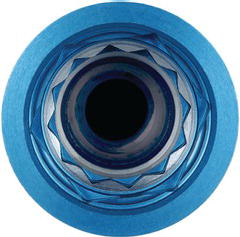
Figure 2.27 A 5 mm EP® Healing Abutment (ITHA54) for 4.1 mm diameter internal connection implant. The apical portion of the healing abutment has been color coded blue for 4.1 mm diameter implants.
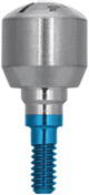
Figure 2.28 A 5 mm EP® Healing Abutment (IWTH54) for 5.0 mm diameter internal connection implant. The apical portion of the healing abutment has been color coded gold for 5.0 mm diameter implants.
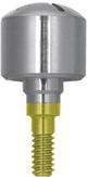
Figure 2.29 A 6 mm EP® Healing Abutment (IWTH64) for 6.0 mm diameter internal connection implant. The apical portion of the healing abutment has been color coded green for 6.0 mm diameter implants.
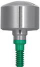
Figure 2.30 Profile view of EP® Healing Abutments for OSSEOTITE® Certain® 5.0 mm implants: 5, 6, and 7.5 mm diameters (left to right). Similar healing abutments are also available for the other implant diameters.
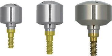
Table 2.4 Catalog numbers for EP® Healing Abutments for 3.4 mm diameter OSSEOTITE® Certain® implants.
| Emergence profile (mm) | Collar height (mm) | Catalog numbers |
| 3.8 | 2.0 | IMHA32 |
| 3.8 | 3.0 | IMHA33 |
| 3.8 | 4.0 | IMHA34 |
| 3.8 | 6.0 | IMHA36 |
Table 2.5 Catalog numbers for EP® Healing Abutments for 4.1 mm diameter OSSEOTITE® Certain® implants.
| Emergence profile (mm) | Collar height (mm) | Catalog numbers |
| 4.1 | 2.0 | ITHA42 |
| 4.1 | 3.0 | ITHA43 |
| 4.1 | 4.0 | ITHA44 |
| 4.1 | 6.0 | ITHA46 |
| 4.1 | 8.0 | ITHA48 |
| 5.0 | 2.0 | ITHA52 |
| 5.0 | 3.0 | ITHA53 |
| 5.0 | 4.0 | ITHA54 |
| 5.0 | 6.0 | ITHA56 |
| 5.0 | 8.0 | ITHA58 |
| 6.0 | 3.0 | ITHA63 |
| 6.0 | 4.0 | ITHA64 |
| 6.0 | 6.0 | ITHA66 |
| 6.0 | 8.0 | ITHA68 |
| 7.5 | 3.0 | ITHA73 |
| 7.5 | 4.0 | ITHA74 |
| 7.5 | 6.0 | ITHA76 |
| 7.5 | 8.0 | ITHA78 |
EP® Healing Abutments are one part of the EP® Emergence Profile System that was developed by 3i® to optimize the gingival contours of implant restorations with stock restorative components (Figure 2.30). In the past, the subgingival contours of implant restorations were left to dental laboratory technicians working on stone casts (Figure 2.31). Clinicians and patients both expect optimal aesthetics, and in some cases prior to development of the EP System, implant restorations were made with ridge lap contours to simulate the gingival margins of natural teeth (Figure 2.32).
In other instances, implant-retained restorations were made from cylindrical abutments and gold cylinders that had straight emergence profiles (Figures 2.33 and 2.34). The subgingival contours for this implant-retained restoration were improved by removing the abutment and placing the appropriate healing abutment (THA464, 4.1 mm implant restorative platform, 6 mm EP® diameter, 4 mm height) for soft tissue healing. The definitive crown was cemented to a prefabricated titanium abutment (GingiHue™ Post, APP464G) that was prepared in the laboratory (Figures 2.35–2.38).
Table 2.6 Catalog numbers for EP® Healing Abutments for 5.0 mm diameter OSSEOTITE® Certain® implants.
| Emergence profile (mm) | Collar height (mm) | Catalog numbers |
| 5.0 | 2.0 | IWTH52 |
| 5.0 | 3.0 | IWTH53 |
| 5.0 | 4.0 | IWTH54 |
| 5.0 | 6.0 | IWTH56 |
| 5.0 | 8.0 | IWTH58 |
| 6.0 | 2.0 | IWTH562 |
| 6.0 | 3.0 | IWTH563 |
| 6.0 | 4.0 | IWTH564 |
| 6.0 | 6.0 | IWTH566 |
| 6.0 | 8.0 | IWTH568 |
| 7.5 | 2.0 | IWTH572 |
| 7.5 | 3.0 | IWTH573 |
| 7.5 | 4.0 | IWTH574 |
| 7.5 | 6.0 | IWTH576 |
| 7.5 | 8.0 | IWTH578 |
Table 2.7 Catalog numbers for EP® Healing Abutments for 5.0 mm diameter OSSEOTITE® Certain® implants.
| Emergence profile (mm) | Collar height (mm) | Catalog numbers |
| 6.0 | 2.0 | IWTH62 |
| 6.0 | 3.0 | IWTH63 |
| 6.0 | 4.0 | IWTH64 |
| 6.0 | 6.0 | IWTH66 |
| 6.0 | 8.0 | IWTH68 |
| 7.5 | 2.0 | IWTH672 |
| 7.5 | 3.0 | IWTH673 |
| 7.5 | 4.0 | IWTH674 |
| 7.5 | 6.0 | IWTH676 |
Stay updated, free dental videos. Join our Telegram channel
VIDEdental - Online dental courses


