Expanding the Limits for Esthetic Strategies by Skeletal Anchorage
Nejat Erverdi, Mustafa Burhan Ateş, Melih Motro
The importance of anchorage in orthodontics can best be described by the famous quote from the Greek philosopher Archimedes: “Give me a place to stand and I will move the earth.” Orthodontic anchorage can also be explained by Newton’s Third Law of Motion, which states that every action creates a reaction, which is equal in size and opposite in direction. The anatomic unit that antagonizes the active force is called anchorage in orthodontics.
Anchorage preparation is a very important part of orthodontic treatment. The success of orthodontic treatment generally relies on the anchorage protocol planned for a particular case. When preparing anchorage, the clinician must be realistic enough to foresee the possibility of losing some anchorage. Anchorage loss can result from unrealistic anchorage construction as well as lack of patient cooperation. The type of anchorage is based on the desired type of tooth movement. Maximum anchorage is frequently required in the treatment of orthodontic cases and is usually obtained by extraoral appliances. Adults and teenagers are prone to reject extraoral appliances because of esthetic problems and the discomfort they cause.1–3 Thus different intraoral mechanics to gain maximum anchorage have been designed by various investigators.
The term stationary anchorage means that the anchorage unit does not move in reaction to the applied orthodontic forces and moments.4 Recent developments in implantology now allow stationary anchorage without extraoral appliances or complex biomechanical procedures. Implants used for orthodontic anchorage are generally classified as osseointegrated or nonosseointegrated implants. Conventional dental implants and palatal implants are considered osseointegrated implants and mini-screws, micro-screws, and various surgical plates are considered nonosseointegrated implants. However, these two concepts are sometimes confused in orthodontics and need to be clarified.
Orthodontic patients usually have an intact dentition with no available sites for implant placements. Therefore various methods for bone anchorage have been tested recently: cobalt-chromium (Vitallium) screws, vitreous carbon, bioglass-coated aluminium oxide implants, stainless steel plates and screws,5–13 Brånemark implants,14,15 retromolar implants,14 onplants,16 zygomatic wires,17 ankylosed teeth,18 palatal implants,19 mini-plates,20,21 and mini-screws.9,13,22 Among these, zygomatic and symphyseal mini-plates have particular importance because they have been widely used and tested in recent years.8
This chapter discusses clinical use of different orthodontic implants to correct different malocclusions. Although orthodontic implants can be used in any case, their use should be limited to cases in which treatment results will be improved when compared with conventional biomechanical procedures or radical surgery, which always carries a risk of morbidity. Otherwise, serious ethical concerns may arise. Therefore the treatment methods presented in this chapter are compared with the conventional methods and advantages, disadvantages, and long-term treatment outcomes are clarified.
Anatomic Sites for Orthodontic Implant Placement
In cases with multiple lost teeth in the dental arch, placement of implants at the beginning of treatment is a useful procedure.23 These implants will serve first as anchor units during orthodontic treatment and then as abutments for the restorations after orthodontic treatment. In such cases the implants must be positioned accurately prior to orthodontics so they can be used as restorative abutments following tooth movement. The overall treatment in these cases must be planned by a team that includes a prosthodontist, orthodontist, and oral surgeon.
In cases without previous tooth loss in the dental arch, orthodontic implants are used only as anchorage units. These are nonroot-form onplants and implants that can be placed in nonalveolar bone and explanted after treatment.19,24,25–30
2. Care must be taken not to create any root, nerve, or artery injury.
3. The implant site must contain enough depth and thickness of bone material.
4. Areas rich in cortical bone are preferred, as they improve the primary stability of the implant.
The hard palate, mandibular retromolar area, inferior border of the zygomatic buttress, symphysis region, and labial or buccal interradicular bone are usually the sites of choice for orthodontic implant placement.
Palatal Implants
The hard palate has long been used as an anchorage site in conventional orthodontics. The Nance button, which is a common anchorage appliance used in the hard palate, is a suitable choice in moderate anchorage situations but it is not sufficient in maximum anchorage requirement. The hard palate is easily accessible to the surgeon and offers excellent peri-implant conditions due to the presence of abundant attached mucosa. Osseointegrated implants placed in the hard palate can be used for anchorage reinforcement in many demanding orthodontic applications.31–33
Anatomic Restrictions in Palatal Implant Placement
Bone Thickness for Implant Placement
The midpalatal suture, the area adjacent to the midpalatal suture, and the incisor region are the areas with maximal bone height in the hard palate. In a computed tomography (CT) study carried out by Gahleitner et al.,34 the overall mean palatal bone height was found to be 5.01-mm, ranging from 0 to 16.9-mm. The maximum palatal height was 6.17-mm, measured 6-mm dorsally from the incisive canal. Henriksen et al.35 reported that the actual bone available for midsagittal implants was 4.3 ± 1.6-mm. The minimum bone thickness necessary for palatal implant placement is 4-mm. These findings indicate that there is sufficient bone for complete osseointegration of 4-mm implants; 6-mm implants should be used with caution.
Incisive Canal Perforation
Implants placed in an anterior location along the midpalatal suture area can create incisive nerve injury. Bernhard et al.36 conducted a study of 22 patients using CT scans and reported that in order not to perforate the incisive canal, the implant must be placed 6- to 9-mm distal to it.
Root Injuries
Palatal implants placed in the anterior slope of the hard palate can cause incisor root injuries. In some cases the implant and incisor root may not be in contact but they can be in close proximity; if incisor retraction is performed as a part of the treatment, root injuries can easily result. The levels of the upper first and second premolars provide the most appropriate anteroposterior site for implant entry.
Placing the Palatal Implant Paramedially
Melsen et al.37 concluded that ossification in the midpalatal suture was variable and was completed after age 27 years in males and even later in females. More recently, Schlegel et al.38 conducted a study on cadavers and reported that complete ossification of the suture was rare before age 23 years. They also stated that since the anterior part of the midpalatal suture was often less ossified than the posterior region, a bone bed more favorable for osseointegration might be found posterior to the interconnecting line of the first premolars.
Both median19,39 and paramedian32,33,40 placements of palatal implants have been reported in the literature. In subjects with complete suture ossification, a median location would not create any problem; however, in subjects with unossified sutures, the implant would be in contact with the fibrous tissue in the suture and therefore the chances of total osseointegration would be less compared to the implants with paramedian implantation. On the other hand, Schlegel et al.38 reported that the connective tissue band in the midpalatal suture area was only 0.03 cm. Considering that the palatal implant has a diameter of 3.3-mm in Orthosystem (Institute Strauman, Waldenburg, Switzerland) and 4.5-mm in the Frialit system (Friadent GmbH, Mannheim, Germany), only a very small portion of the implant would be in contact with the connective tissue when it is placed in the midpalatal suture area, minimizing the concerns about poor osseointegration.
Another critical issue is the possible effect of an implant placed in the midpalatal suture on transverse growth of the maxilla. Growth in the midpalatal suture increases the width of the palate and is considered to be more important than appositional remodeling of the alveolar processes in the development of maxillary width.41 Björk and Skieller42 found an average increase in maxillary width of 3-mm between ages 10 and 18 years, as measured between posterior implants on the radiographs of nine boys. Asscherickx et al.43 evaluated the influence of orthodontic anchorage implants on transverse maxillary growth when inserted in the median palatal suture of growing dogs and reported restricted transversal growth of hard palate in the canine region. Because of ethical considerations, such investigations can be carried out only in animals. In light of these findings, paramedian placement of palatal implants may be recommended in growing individuals.
Palatal Artery Injury
There is always a risk of causing an arterial injury in punch burr application. To prevent bleeding during the operation, infusion of an anesthetic with a vasoconstricter agent is recommended around the area where the implant will be placed. In cases where there is aggressive bleeding, suturing of the artery is recommended.
To avoid the complications described above, an implant must be placed with special care. An acrylic resin template, including a cylindrical metal housing (similar to the stents that are used in implantology for prosthetic purposes), must be used. A method that was developed for precise placement of palatal implants is explained next.
Method for Palatal Implant Placement
Preparation of Acrylic Resin Template
A spherical metal marker is embedded in an acrylic resin template, which covers the occlusal surfaces of the maxillary teeth. The metal marker is placed at the highest point of the palate in the midline. The purpose of placing a metal marker is to calculate the magnification of the radiograph when assessing the exact bony dimensions of the area where the implant will be placed. At least 4-mm of bone thickness is required in this area. Moreover, the metal marker creates a reference point in the sagittal direction for identifying the location of the drilling site for implant placement.
Radiographic Evaluation
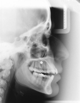
A lateral cephalogram with the patient wearing the maxillary acrylic template is obtained (Fig. 19-1). Bone depth in the area where the implant will be placed is measured in relation to the metal marker, which has a diameter of 5-mm. Cases having at least 4-mm of bone height are considered suitable for palatal implant placement and cases without enough bone thickness are candidates for onplant placement.
Preparation of the Surgical Template for Positioning the Implant
The plaster cast used for template preparation is cut along the paramedian line, passing through the mesial aspect of the central incisor. On the lateral cephalogram, radiographic views of the maxilla and central incisor are traced on tracing paper and then a cut is made along the pencil line and carried to the paramedian section of the plaster cast. A drill insertion hole is prepared in the acrylic resin template, using a 2.5-mm-diameter stainless steel burr. A cylindrical metal housing, 7-mm in length and 2.1-mm in diameter, which contains a pilot drill, is placed in the implant access hole. The extension of the implant drill is adjusted to 8-mm from the metal housing. In the sagittal plane the desired implant inclination in relation to the incisor roots and the nasal cavity is defined. The implant axis is adjusted between 45 and 60 degrees to the occlusal plane, pointing to the anterior nasal spine (ANS). Care is taken to place the implant at least 3- to 4-mm above the apices of the incisor roots. The metal housing is fixed to the acrylic plate by some cold curing acrylic. In the transverse plane the metal housing should have a lateral orientation with 2-mm of distance from the palatine suture. Thus a three-dimensional surgical template for accurate implant angulation is obtained (Fig. 19-2).
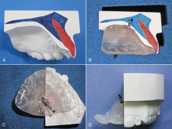
Figure 19-2 A, Maxillary tracing is superimposed on the model. B, The pilot drill should be oriented between 45 and 60 degrees to the occlusal plane. The drill axis should pass at least 3- to 4-mm above the apices of the incisors. C, The metal housing is fixed to the template with cold curing acrylic. D, In the frontal plane the pilot drill should be laterally oriented about 2-mm from the median line.
Surgical Method
Before the surgical procedure the patient is asked to rinse his or her mouth with 0.2% chlorhexidine gluconate for 1 minute. After this rinsing the palatal region is locally anesthetized with an agent that has a vasoconstrictive effect. The three-dimensional surgical template is placed in the mouth to mark the implant position. A pilot drill is applied through the metal housing in the template. Then mucosa is removed using a punch drill and the standard surgical protocol for placing the chosen implant system is followed. Drilling is carried out at 1000 revolutions per minute (rpm) under internal and external sterile saline cooling. Drills with 8-mm-long stoppers are used in the following order: a pilot drill of 2-mm diameter, a twist drill of 3-mm diameter, and a spade drill of 4.5-mm diameter (Fig. 19-3, A–E).
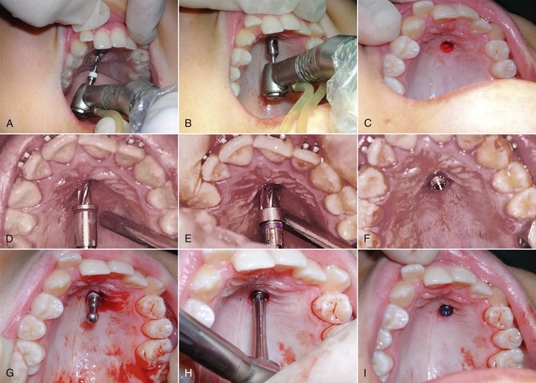
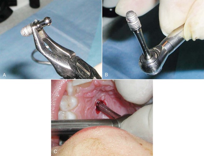
Figure 19-3 A, Pilot drill application through the metal housing in the template. B, The template is removed from the mouth and a punch drill is applied to the implant site to remove the mucosa. C, Implant site after removal of the mucosa. D and E, Preparation of the implant bed. F, Placement of the palatal implant. G, Removal of the implant carrier. H and I, The implant is screwed into place.
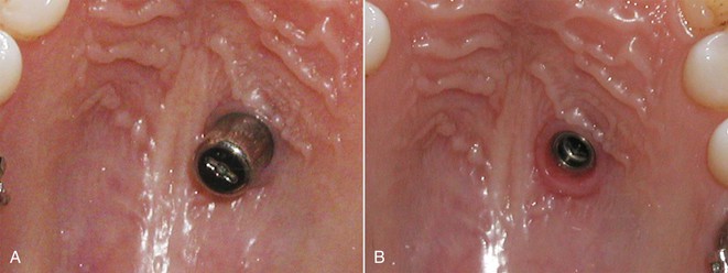
In the standard surgical protocols for almost all implant systems, the implant carrier is removed after the initial placement of the implant in the cavity before screwing. The implant is placed transmucosally so that 4-mm of the implant will stay in the bone and 4-mm will stay in the palatal mucosa and serve as an extension to reach the oral cavity (Fig. 19-3, F–I). Transmucosal placement of the implant has the advantage of avoiding the need for secondary surgery. To avoid postoperative pain an analgesic agent is recommended and the patient is instructed to use an antiseptic mouthwash twice a day for 2 weeks. The osseointegration of the palatal implants takes about 3 months and during this period the implant should not be loaded. After waiting 3 months for osseointegration, a gingiva former of proper size is screwed to the implant. One week is usually enough time for shaping of the palatal mucosa (Fig. 19-4).
Evaluation of Implant Placement Method
The accuracy of the implant placement method was tested by superimposing the presurgical lateral cephalogram with the template and the postsurgical lateral cephalogram with the implant (Fig. 19-5).
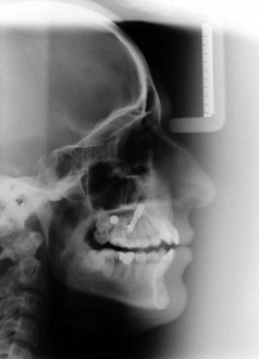
Figure 19-5 Superimposition of the presurgical and postsurgical lateral cephalograms taken with the template in the mouth. The implant is located on the same axis as the metal housing, indicating the accuracy of implant positioning.
The method seems to be successful and practical, with only a few complications such as slight bleeding, which can be easily controlled. Patient comfort during and after the operation is excellent and the procedure does not last more than 10 minutes. The only risk related to this procedure is the possibility of the implant carrier being swallowed by the patient while it is being removed in the conventional way. The location of the implant and possible vomiting reflex during removal of the implant carrier are the two factors that create this risk. To avoid this risk a safe method was developed especially for the removal of the implant carrier.
To avoid the risk of the implant carrier being swallowed, it is recommended that it be removed outside the mouth and that the implant be carried to the cavity while it is seated on the screwing instrument. Care must be taken to hold the implant with Weingart pliers at the polished band, which is designed normally for gingival attachment. The implant holder is removed while the implant is held by Weingart pliers and seated on the screwing instrument. Then the implant is carried to the cavity by the screwing instrument and screwed on directly (Fig. 19-6).
Laboratory Procedures
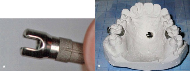
After completion of the healing period, a transfer kit is screwed to the implant and a plastic cap is mounted. Molar bands and an impression post are transferred to the plaster cast by a conventional impression technique. If needed, premolar bands are transferred as well. An orthodontic abutment (Friadent, Mannheim, Germany) is fixed to the implant analog on the plaster (Fig. 19-7).
Stationary Anchorage
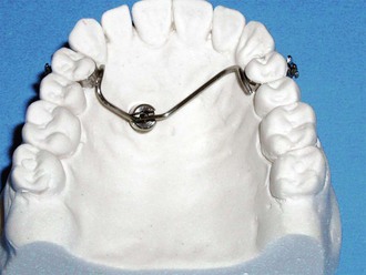
On the stone model, a transpalatal arch made of 1.2-mm-thick stainless steel wire is adjusted to connect the anchor teeth to the orthodontic abutment and then is soldered to the bands (Fig. 19-8). Care should be taken not to overheat the wire and not to create dead wire, which can be a cause of anchorage loss.
Orthodontic Mechanics with Palatal Implants
Using this stationary anchorage supported by a palatal implant, various procedures such as en masse retraction of six anterior teeth, canine distalization, and correction of excessive crowding can be carried out without any anchorage loss.
Stay updated, free dental videos. Join our Telegram channel
VIDEdental - Online dental courses


