Chapter 19 Cutting instruments
Learning Objectives
From this chapter, the reader will:
• Understand the key design features and types of dental handpieces and their role in operative procedures
• Have an improved appreciation of the types of burs available: their design, function and indications including how best to use them and their interaction with dental materials
• Know what other cutting instruments are used in dentistry, including air abrasion and lasers
• Understand the effect of sandblasting on a range of substrates and have confidence in using this technique clinically
• Understand the importance of polishing and be aware of the instruments available to achieve this
• Understand the collateral damage that incorrect polishing may cause to materials/substrates, including dental hard tissues
• Know the names of currently available commercial products.
Introduction
Cutting instruments are, of course, not dental materials per se, but the effect they have when used with dental materials and on tooth tissues is of great clinical significance. This chapter discusses the equipment used to cut and polish both dental materials and tooth tissues. Other techniques such as sandblasting, air abrasion and laser cutting, which have found many indications in modern dentistry as they are much less invasive, are also described.
Dental Handpieces
Working at high speeds (in excess of 180 000 rpm)
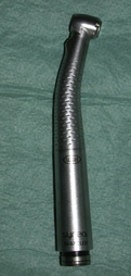
• High-speed handpiece, also known as an air rotor or air turbine (Figure 19.1). As its name implies, it is driven by a supply of compressed air.
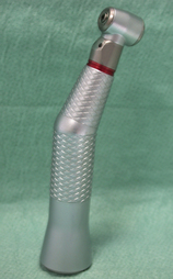
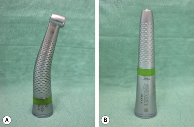
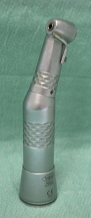
• Speed-increasing handpiece (Figure 19.2). These are generally driven by an electrical motor. They achieve their speed by using a gearing mechanism much like a gear box in a car.
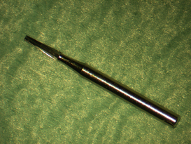
Both the air driven high-speed instrument and the speed-increasing handpieces use friction grip (FG) burs, the bur being the cutting component of the system (Figure 19.3). The bur is slid into the jaws of the chuck while these are open and then the jaws are released to grip the bur shank. Box 19.1 illustrates how a friction grip bur should be inserted correctly into a high-speed or speed-increasing handpiece.
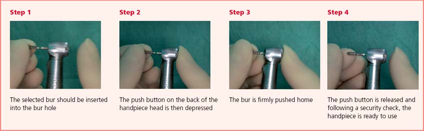

A high-speed or speed-increasing handpiece should never be run without fully inserting the bur into the chuck. If the bur is only partly inserted into the chuck, it may be released during use and cause intraoral soft tissue injury or be lost into the patient’s oropharynx. In addition, any eccentricity in the running of the chuck will be exaggerated. This will damage the chuck and the bur. If the bur is too short to access the operating site, it should be changed for one of a greater cutting length (see fig 19.31, p. 335).

High-speed handpiece
Internal structure
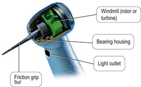
The turbine is powered by compressed air, which passes up the central lumen of the instrument. The air pressure is usually 3 bar (43.5 psi) although this varies depending on the handpiece manufacturer’s advice. This column of air then strikes the blades of a windmill in the handpiece head, causing it to rotate. The chuck is at the centre of the windmill. As the windmill rotates, so does the bur. The internal components of a high-speed handpiece are shown in Figures 19.4 and 19.5.
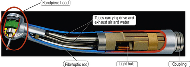
Fig. 19.4 A cut away view of a high-speed handpiece with the primary components identified.
Reproduced with kind permission of W & H.
• The bur to judder. This leads to vibration that is then transmitted to the material being cut, causing cracking and crazing. This vibration may also be unpleasant for the patient. It can cause the bur to break as it may snatch against the cutting surface.
• Eccentric cutting. This will result in irregular removal of the tissue being prepared so more tissue is removed than is necessary.
• Less control for the dentist due to the irregular cutting.
Cooling
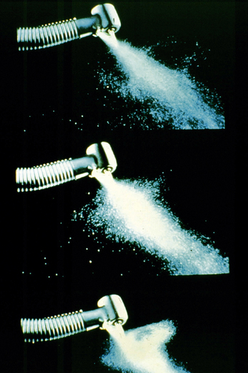
As significant heat is generated during cutting due to friction, it is critical that effective cooling is provided over the whole cutting surface of the bur. Water is generally used to cool the bur. It is transported to the handpiece head via fine tubes within the body of the handpiece and exits via a number of small outlet holes, which are aligned to deliver the water onto the bur (Figure 19.6).

It is desirable to have at least four holes, preferably more. This is because during use the position of the handpiece may prevent one or more holes directing water to the bur. The water may be also deflected away from the bur by the surface being cut. This compromises the supply of water to the bur and hence the cooling efficiency (Figure 19.7).
Illumination
Many modern handpieces now have a light in close proximity to the bur. This is directed at the cutting surface so that the area being worked on is illuminated directly rather by reflection via a mouth mirror, increasing the dentist’s clarity of vision. The original lights were small halogen bulbs, with the light being transmitted to the handpiece head using a fibreoptic rod. Halogen bulbs deteriorate with time in use and have relatively a short life. They are also expensive to replace. Furthermore, the glass fibreoptic rod was prone to breakage if the handpiece was dropped, and deteriorated with time due to repeated decontamination cycles in the autoclave. Many manufacturers have now moved onto using low-power light emitting diodes (LEDs). The resulting light is whiter, more intense and the working life is much longer. LEDs are also relatively stable in wavelength over their lifetime and low-power LEDs produce little or no heat. The rapidly developing LED technology may well see considerable advances in product design and usage featuring these components in future.
Grip
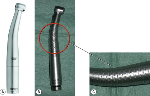
Handpieces are either knurled or smooth in their external design and this is very much personal preference. Many practitioners prefer the knurled finish as this provides more stability and control of the handpiece. This is especially so when wearing gloves as the dentist’s grip on the handpiece is enhanced. It is important that the knurling is not too deep or close together to avoid compromising cleaning and sterilizing of the instrument (Figure 19.8).
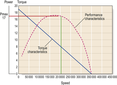
The importance of torque
To allow the bur to continue to rotate, the power must be maintained. The relationship of power, torque and speed are illustrated in Figure 19.9. Power is difficult to maintain with an air supply as the air pressure is not supplied at a constant level and may fluctuate depending on the draw down of air from the compressor. This will have an effect on the speed of the bur and hence the torque. The air pressure should be set at 2–3 bar (29–43.5 psi) and should be confirmed using an air gauge. There may be significant fluctuations in air pressure due to the various demands on the compressor due to demand from other clinics in a multi-clinic practice.
Indications for using an air rotor handpiece
Speed-increasing handpiece
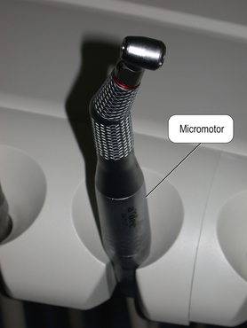
The speed-increasing handpiece (Figures 19.2 and 19.10) is driven by an electrical motor, also called a micromotor. The handpiece is placed onto the coupling of the micromotor on the dental unit (Figure 19.11).
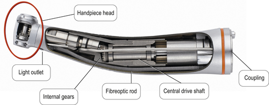
Fig. 19.10 A speed-increasing handpiece with its components labelled.
Reproduced with kind permission of W & H.
Mode of cutting
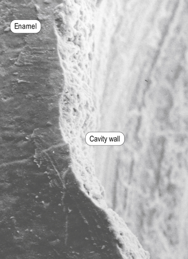
A bur in a speed-increasing handpiece runs more smoothly compared with a bur in a turbine The bur in a turbine also moves axially (in and out) during use, resulting in a pecking motion being transmitted to the material being prepared. This pecking motion causes a rippling effect on the material, leading to the formation of microcracks (Figure 19.12).
To prevent microcracks, many operative dentists are now moving onto using speed-increasing handpieces in preference to turbines. This is particularly so when doing work that requires a smoother running bur and precision such as refining tooth preparations, tooth hemisections and polishing. These handpieces also produce less noise and vibration.
Comparison of high-speed and speed-increasing dental handpieces
A comparison of the features of high and low speed handpieces are set out in Table 19.1.
Table 19.1 Comparison of the features of high-speed and speed-increasing handpieces
| High-speed | Speed-increasing | |
|---|---|---|
| Type of bur used | Friction grip | Friction grip |
| Power source | Compressed air | Electric micromotor |
| Torque | Variable | Constant |
| Motion of bur | Rotation and pecking | Rotation only |
| Balance | Usually neutral | Motor end heavy |
Slow-speed handpieces
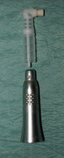
Handpieces that operate at a slower cutting speed, that is, between 600 and 250 000 rpm are available as either contra-angle or straight (Figure 19.13).
The internal workings of slow-speed handpieces are essentially the same as previously described for the speed-increasing handpiece as shown in Figure 19.11. The main differences between them are:
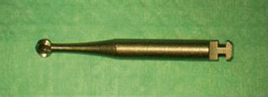
• The slow-speed handpiece uses a latch grip bur (Figure 19.14) instead of the friction grip bur used in the speed-increasing handpiece.
Indications for slow-speed handpieces
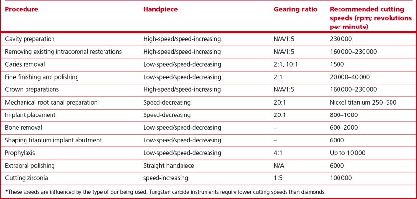
Contra-angle handpieces are generally used for operative procedures such as the removal of dental caries and for polishing enamel and restorative materials intraorally. Straight handpieces are used in oral surgical procedures or for the extraoral adjustment and polishing of acrylic and metals. The speed of the handpiece will depend on the task. Table 19.2 lists the cutting speeds for common dental procedures and materials.

Most dental handpieces (except air turbines) have coloured rings on the body of the handpiece. These rings denote the handpiece’s internal gearings. This feature is illustrated in many of the photographs in this chapter. The colour codes are explained in Table 19.3.
Table 19.3 Ring colour and internal gearing of dental handpieces
| Ring colour | Gearing |
|---|---|
| Red | Increase usually 1:5 but may also be other ratios |
| Blue | 1:1 |
| Green (or double green) | Reduction may be 2:1, 4:1, or 20:1 but not related to a specific ratio |

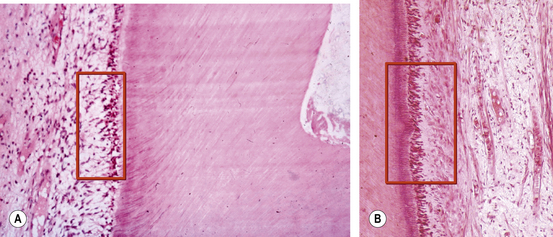
It is advisable to use water cooling even when cutting at slow speeds to:
• Reduce the substantial heat generated by friction. This heat can lead to deleterious effects on the dental pulp (Figure 19.15). Water cooling is more efficient at dissipating the heat than air.
• Excessive heat also has detrimental effects on the substrate, possibly causing it to melt. This melted material can clog the cutting surface of the instrument so resulting in reduced efficiency of the cutting or polishing process. More heat will be generated with larger amounts of the surface area of abrasive in contact with the substrate surface.
• Improve the dentist’s vision of the area being prepared, as the water will wash away most debris produced.
Speed-decreasing
Some handpieces are designed to work at slower speeds and are termed speed-decreasing handpieces (Figure 19.16).
Indications for use of speed-decreasing handpieces
The main indications of speed-reducing handpieces are:
• Endodontic canal preparation. Root canals should be prepared using a slowly rotating file. Many endodontic handpieces also have a design feature to control the torque, with the aim of preventing endodontic file separation during use.
• Implant placement. The slow speed of rotation reduces the heat produced by friction so preventing damage to the bone cells that are needed for osseointegration.
• Prophylaxis. As the speed is slower, the heat produced and transmitted to the tooth during polishing is reduced. The slower speed also reduces the amount of the prophy paste (see p. 345) being sprayed everywhere! This phenomenon can be further reduced by using a reciprocating prophylaxis handpiece (Figure 19.17).

Stay updated, free dental videos. Join our Telegram channel
VIDEdental - Online dental courses


