Achieving Optimal Esthetics with Palatal Mini-Implants
The Benefit Technique
Benedict Wilmes
The advent of mini-implant technology continues to broaden the spectrum of what is achievable by orthodontics. The challenges associated with certain types of tooth movement can now be overcome by applying sound biomechanical principles to skeletal anchorage with even more potential for ideal esthetic outcomes. This chapter discusses the use of different forms of skeletal anchorage and considerations to achieve optimal esthetic goals.
Stable Anchorage
Orthodontic mini-implants have become increasingly popular in recent years because of their versatility, minimal invasiveness, and low cost.1–5 Their small size allows them to be inserted in a variety of sites. Currently, the alveolar process is the most preferred insertion site. However, due to varying bone quality and the risk of root contact, the survival rate of implants inserted in the alveolar ridge still needs improvement, with current failure rates at approximately 10% to 30%.6–11 The following factors seem to be relevant for the premature loss or tipping of a mini-implant:
1. Insufficient bone quality and/or inadequate bone quantity at the insertion site.12–14
2. Employment of mini-implants with a small diameter and/or length.9,15–17
3. Inappropriate intraosseous design.17–19
4. Root contact at the time of insertion.20
5. Manipulation with the fingers or tongue.15
7. Application of high forces or moments.16,21
8. Use of a large lever arm. This occurs if the mini-implant is inserted in a region where the gingiva or mucosa is too thick.16,21,22
9. Insertion in the region of the movable mucosa.8,15
10. Insufficient primary stability.2,22–24
11. Bone damage at insertion due to high stress or bone overheating.8,25 This phenomenon is well known in dental implantology.26
Other regions, such as the anterior palate and the mental region, provide much better conditions for temporary anchorage device (TAD) insertion since the amount and quality of the available bone is superior.27 Using TADs in the anterior palate and the mental region eliminates the risk of root injury and takes the TADs out of the path of tooth movement.
Benefit Mini-Implants with Exchangeable Abutments
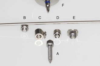
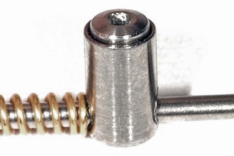
The Benefit mini-implant has an inner thread on its top (Fig. 18-1; PSM, Tuttlingen, Germany; PSM North America, Indio, CA). It is made of titanium alloy (Grade 5: Ti-6Al-4V) and due to its self-drilling thread design, insertion can be done without predrilling with a handpiece. Available dimensions are diameter of 2 or 2.3 mm and length of 7, 9, 11, 13, or 15 mm. On the top of the mini-implant four different types of stainless steel abutments can be fixed with a tiny fixing screw that is integrated into the abutment (Fig. 18-2). This small fixing screw can be turned within the abutment but cannot fall out of it. Different types of abutments allow the construction of versatile appliances for a large variety of clinical applications. The Benefit mini-implants are inserted primarily in the anterior palate and in edentulous areas of the alveolar process.
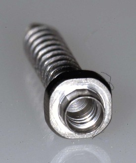
Figure 18-1 Benefit mini-implant with an inner thread.
The Beneplate: A Mini-Plate for the Easy Coupling of Two Mini-Implants
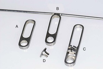
To improve their stability and to prevent mini-implant tipping, two Benefit mini-implants can easily be coupled with the Beneplate (Fig. 18-3; PSM). The Beneplate is a stainless steel plate with a thickness of 1.2 mm. To cover multiple distances of two mini-implants, it has a round hole and a long hole. As well, it is available in two different lengths, resulting in possible distances of 3.5 to 14 mm measured from the center of one mini-implant to the center of the other. To enable a stable connection to the orthodontic appliance, Beneplates with a 1.1-mm-diameter stainless steel wire (for a Beneslider, Mesialslider, Mesial-Distal-Slider), a 0.8-mm-diameter stainless steel wire (for a Pendulum B or molar intrusion with the Mousetrap mechanics), and a stainless steel bracket (to ligate in lever arms) are available (see Fig. 18-3). The Beneplate can be adapted to the Benefit mini-implants by bending the plate body as well as the wire. Small fixing screws are used to fix the Beneplate on top of the mini-implants (see Fig. 18-3).
Step-by-Step Clinical Procedure
The optimum insertion site in the maxilla is located in the anterior palate distally from the palatal rugae on a line between the premolars. Advantages of this region are a thin soft tissue layer and sufficient bone height. Less bone is available in the areas that are more lateral and posterior (Fig. 18-4).28,29 The first step is local anesthesia administered directly in the insertion site (Fig. 18-5). If the patient is afraid of a syringe, only topical anesthesia can be used. The second step is predrilling (to 3 mm depth) with a 1.4-mm drill for the 2-mm mini-implants and a 1.7-mm drill for the 2.3-mm mini-implants. This can be done manually using a special handpiece equipped with a 1 : 1 contra angle (Fig. 18-6; PSM). Due to the low speed there is no need for cooling. In very young patients (i.e., less than 12 years of age) predrilling is not necessary due to the low mineralization rate of the bone.
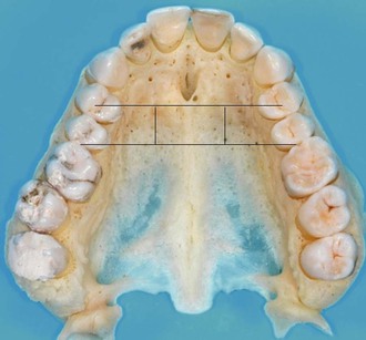
Figure 18-4 Prepared maxilla with two lines showing the optimal insertion site between the premolars. Less bone is available in the areas that are more lateral and posterior.
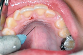
Figure 18-5 Local anesthesia administered directly into the insertion site using a SOPIRA Citoject syringe (Heraeus Kulzer GmbH, Hanau, Germany).
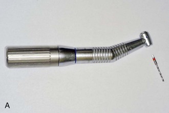
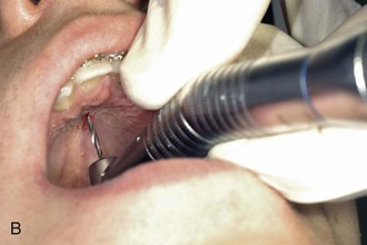
Figure 18-6 A, Preparation for predrilling using a contra angle equipped with a special handpiece. B, Predrilling with the contra angle and the handpiece.
Once the sites have been prepared, one or two Benefit mini-implants are inserted near the midpalatal suture, again using the contra-angle screwdriver (Fig. 18-7). If just one mini-implant is employed (e.g., for molar anchorage), the dimension 2.3 mm × 11 mm is chosen (Fig. 18-8); if two mini-implants are employed, usually a 2 mm × 11 mm mini-implant is inserted anteriorly and a 2 mm × 9 mm mini-implant is inserted posteriorly. As an alternative, a 2 mm × 9 mm mini-implant is chosen anteriorly and a 2 mm × 7 mm mini-implant is chosen posteriorly (Fig. 18-9). Generally, it is advisable to choose mini-implants with a big diameter of 2 or 2.3 mm, because they provide superior stability compared to mini-implants with a smaller diameter.22 Usually the Benefit mini-implants are inserted within a torque range of 10 to 25 Newton centimeters (Ncm).30 The maximum insertion torque is 35 Ncm for the mini-implants with a diameter of 2 mm.31 Usually, two mini-implants are inserted in a sagittal line (Fig. 18-10, A). As an alternative and especially if a rapid palatal expansion with the Hybrid Hyrax is planned, the mini-implants are inserted in a transversal lineup (Fig. 18-10, B). The distance between the two mini-implants should be at least 4 mm to enable enough space for the supraconstruction (two abutments or one Beneplate). Additionally, if an impression is planned, there must be enough space for two impression caps. The Benefit mini-implants are self-drilling and can be inserted without predrilling. However, there is very high bone density in the anterior palate, especially in older patients. Soft tissue thickness can be measured using a dental probe from anterior to posterior to identify a region with thin mucosa. This is important in order to achieve a sufficient primary stability and to avoid large lever arms.21,22 The soft tissue in the anterior region nearby the first and second rugae is very thick.29
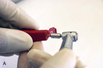
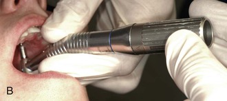
Figure 18-7 A, Preparing a Benefit mini-implant before insertion. B, Insertion of a Benefit mini-implant using the contra-angle screwdriver.
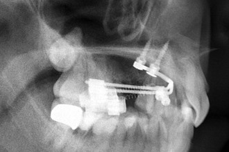
Figure 18-9 Two Benefit mini-implants inserted in the palate (2 mm × 11 mm anterior and 2 mm × 9 mm posterior).

Figure 18-10 A, In most cases, two mini-implants are inserted in a sagittal line. B, If a rapid palatal expansion with the Hybrid Hyrax is planned, the mini-implants are inserted in a transversal lineup.
Depending on the mechanics, bands with lingual sheaths are fixed to the upper molars. The appliance can be bent either directly chairside (Fig. 18-11) or after impression taking in the laboratory. In the latter case, impression caps (Fig. 18-12, A) are placed on top of the mini-implant (Fig. 18-12, B and C) and a silicone impression is taken (Fig. 18-12, D). If desired, the impression caps can be secured by dental floss. Subsequently, laboratory analogs are inserted in the impression caps and fixed by wax (Fig. 18-12, E). At the end, a plaster model is manufactured. The only appliance that has to be manufactured in the laboratory is the Hybrid Hyrax since it requires soldering or welding connections. Bands should be adapted on the teeth and later in the impression if they will be integrated in the appliance (Fig. 18-12, F).
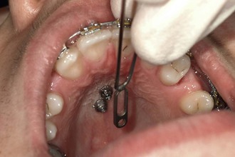
Figure 18-11 Chairside adaption of the T-bow for front anchorage during molar mesialization in the upper arch.
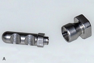
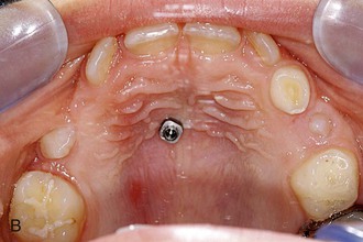
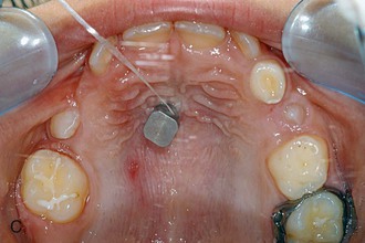
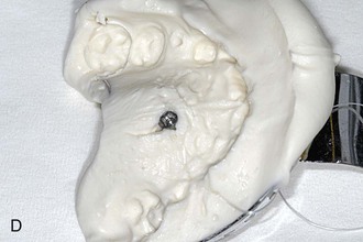
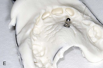
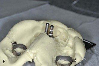
Figure 18-12 A, Laboratory analog (left) and impression cap (right). B, One Benefit mini-implant after insertion. C, An impression cap is placed on top of the mini-implant. D, Impression tray. Note that the impression cap is visible. E, A laboratory analog is inserted in the impression cap. F, Impression for a Hybrid Hyrax with replaced bands and laboratory analogs.
The mini-implants are loaded immediately after insertion; in the case of a laboratory procedure, they are loaded a maximum of 1 week after insertion of the TADs. It is recommended that the appliance be inserted as soon as possible. If there is a long period until the appliance is fixed, the patient has time to jiggle the mini-implants with the tongue or fingers and as a consequence they may become loose.
Distalization in the Upper Arch
Principle: Direct versus Indirect Anchorage
Class II malocclusions are very common. For patients with a dental Class II malocclusion with increased overjet and/or anterior crowding, upper molar distalization is a frequently chosen treatment alternative. Molar distalization with a headgear is unpleasant for many patients for esthetic reasons and because of the length of time the headgear needs to be worn.32,33
These factors resulted in a tendency to prefer purely intraoral appliances that require minimal patient cooperation. Unfortunately, most conventional devices for noncompliance upper molar distalization produce unwanted side effects such as anchorage loss.34 One possible method to reduce unwanted orthodontic effects of reciprocal forces is the use of palatal acrylic pads (Nance buttons). However, the anchorage stability of this soft tissue–borne element is not always certain. Moreover, oral hygiene is impaired due to the partial coverage of the palatal area. If the anchorage unit includes teeth, mesial migration and/or protrusion of the anterior dentition must be considered as a major drawback.34–36 Anchorage loss of conventional intraoral distalization devices ranges from 24% to 55%.34
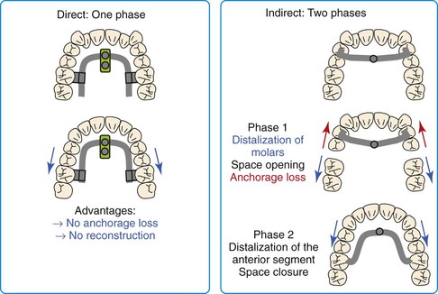
To minimize or eliminate anchorage loss of the anterior dentition, skeletal anchorage devices have been integrated into distalization appliances.37–46 Although indirect anchorage can be used to support the premolars during maxillary molar distalization, mini-screw tipping and wire deformation may result in anchorage loss and mesial premolar migration. Moreover, after molar distalization the appliance must be reconstructed in order to distalize the premolars and anterior teeth. Therefore direct anchorage is preferable (Fig. 18-13).
Direct Anchorage with the Beneslider
The Beneslider3,30,47,48 is a distalization appliance that uses direct anchorage and is based on one (Fig. 18-14, A) or two (Fig. 18-14, B) mini-implants in the anterior palate. Through the use of the Benefit mini-implants with exchangeable abutments, a stable and safe connection between the mini-implants and the distalization mechanics is achieved. To couple the Beneslider with the molars, bands with lingual sheaths are fixed to the upper molars. Directly thereafter, Benetubes are plugged into the sheaths from the mesial side (Fig. 18-15). To avoid irritation of the soft tissues, the Benetube must be bent slightly in most cases. If one mini-implant was inserted, an abutment with a wire in place (see Fig. 18-2) is adapted to the curvature of the palate. If two mini-implants were inserted, a Beneplate with a 1.1-mm stainless steel wire in place (see Fig. 18-3) is now adapted (see Fig. 18-15, B). Depending on the axis and the location of the two mini-implants, the Beneplate body must be bent (Fig. 18-16). By changing the angulation of the 1.1-mm stainless steel wire, it is possible to achieve a simultaneous intrusion or extrusion of the molars (Fig. 18-17). The adapted abutment is now fixed on the mini-implant by the inner fixing screw. If two mini-implants were inserted, the Beneplate is fixed by two fixing screws (see Fig. 18-3, D). This can be performed with the screwdriver or with the contra angle and the handpiece (Fig. 18-18). Finally, the distalization force is applied by springs that are activated by pushing the activation locks distally (Fig. 18-19). The author recommends the use of nickel-titanium (Ni-Ti) springs (240 g in children and 500 g in adults). It seems advantageous that the Beneslider mechanics can be installed without need for any laboratory work in terms of welding or soldering. In other words, the Beneslider mechanics can be applied directly in the oral cavity without taking an impression. To save chair time, however, the Beneslider can also be adapted on a plaster model (see Fig. 18-12).
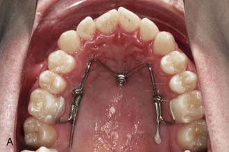
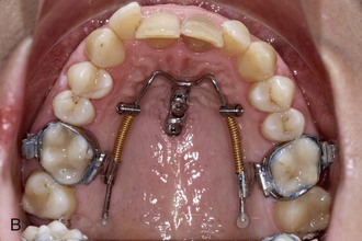
Figure 18-14 A, Beneslider based on one mini-implant (2.3 mm × 11 mm). B, Beneslider based on two mini-implants (2 × 11 mm anterior and 2 × 9 mm posterior).

Figure 18-15 A, Benetube is plugged into the sheaths from the mesial side. B, Afterwards, the wire of the Beneplate must be adapted to the curvature of the palate.
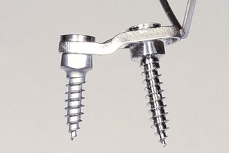
Figure 18-16 Bending of the Beneplate body.
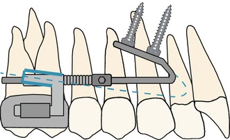
Figure 18-17 By changing the angulation of the 1.1-mm stainless steel wire, it is possible to achieve a simultaneous intrusion or extrusion of the molars. The dashed blue line represents the mechanics for intrusion during distalization.
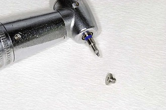
Figure 18-18 Tiny screw used to fix the Beneplate on top of the mini-implant. This can be performed with the screwdriver or the contra angle (shown).
Follow-up should be scheduled every 4 to 6 weeks. Usually the premolars and canines migrate distally toward the molars due to stretching of the interdental fibers. After distalization of the molars with the Beneslider, the Beneslider stays in place as an anchorage device during retraction of the anterior dentition. The treatment can be finished with buccal brackets, lingual brackets, or aligners.
Clinical Example Using the Beneslider
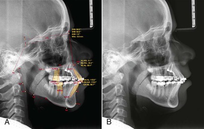
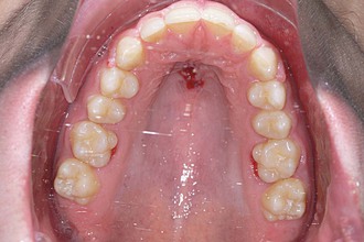
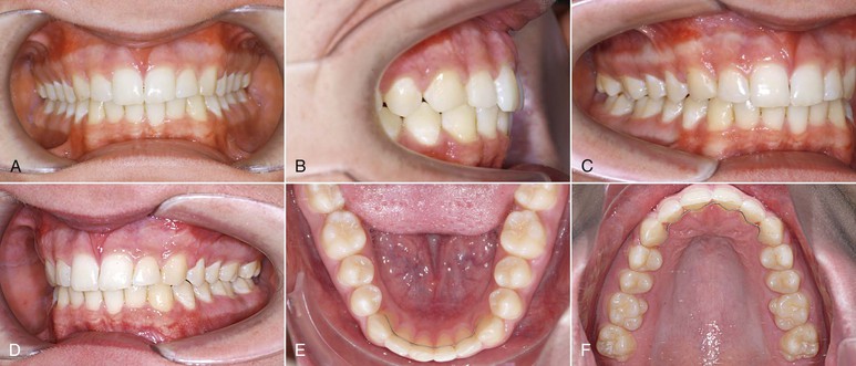
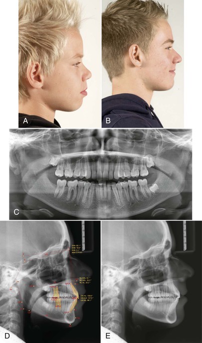
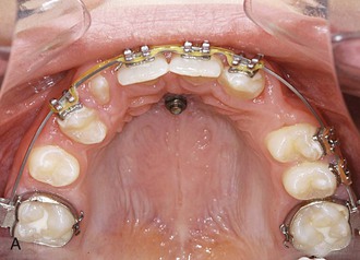
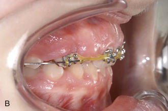
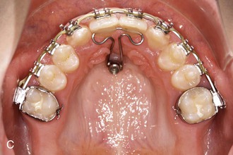
The patient was a 13-year-old male with a Class II relationship and severe bialveolar protrusion. In the canine region, half of a Class II occlusion was found (Figs. 18-20 and 18-21). The treatment plan was distalization and correction of the protrusion in the upper arch with a Beneslider and distalization with a lip bumper and retrusion of the incisors in the lower arch. After insertion of two Benefit mini-implants in the anterior palate, the Beneslider mechanics were applied and activated (Fig. 18-22, A). After 6.5 months the upper molars were distalized approximately 4 mm and brackets were bonded (Fig. 18-22, B). The radiographs show a bodily distalization of the molars (Fig. 18-23). Steel ligatures were inserted between the Benetubes and the activation locks to deactivate the Beneslider. As an alternative, the Ni-Ti springs can be removed. In other words, the Beneslider was modified from a distalization device to a molar anchorage device. An elastic chain was inserted from the first molar to the contralateral first molar to retract the anterior dentition. After 5 months of retraction the spaces were almost closed to the distal. To avoid contact of the Beneplate wire and the soft tissues it is important to anticipate the amount of front retraction at the time of bending the wire; in this case, this issue was not properly addressed (Fig. 18-24). After the finishing phase the brackets were debonded. The Beneslider and the Benefit mini-implants were removed without anesthesia (Fig. 18-25). End of treatment was reached after 18 months (Figs. 18-26 and 18-27).
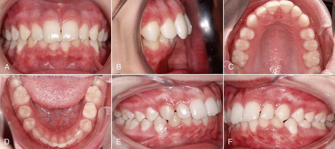
Figure 18-20 A–F, Intraoral photographs of 13-year-old male patient with Class II malocclusion and severe bialveolar protrusion.
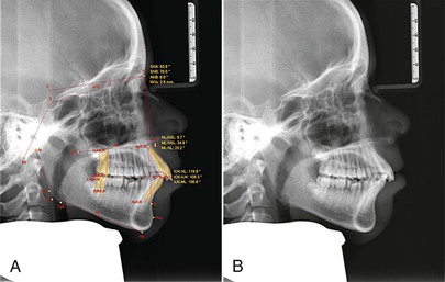
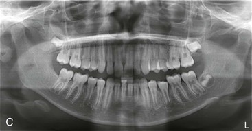
Figure 18-21 A and B, Cephalometric and (C) panoramic radiographs showing a dentoalveolar class II and a front protrusion.
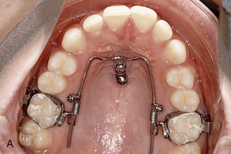
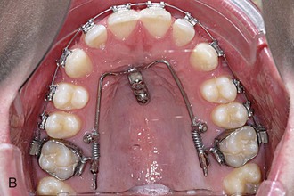
Figure 18-22 A, The Beneslider in situ. B, After 6.5 months the upper molars were distalized approximately 4 mm and brackets were bonded.
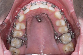
Figure 18-24 Continuation of front retraction.
Mesialization in the Upper Arch
Principle: Direct versus Indirect Anchorage
Congenitally missing lateral incisors or second premolars, extremely displaced canines, or a severe trauma of a central incisor are potential complaints that result in a reduced upper dentition. The two major treatment approaches are space closure or space opening to allow prosthodontic replacements with either a fixed prosthesis or a single-tooth implant. Both of these treatment approaches can potentially compromise esthetics, periodontal health, and function.49 In many cases space closure to the mesial (front teeth should stay where they are, when posterior teeth are moving mesially) seems to be the favorable treatment goal, since treatment can be completed as soon as the dentition is complete.50 Canine substitutions can be accomplished with good esthetic outcomes by tooth reshaping and positioning, bleaching, and porcelain veneers.51,52
The more mesial the missing tooth is, the higher will be the demands for anchorage quality, especially in asymmetrical cases with a midline deviation. If the central incisors are in the correct position (midline, torque, and angulation is correct), a T-bow3,30,49,53 can be bonded to the lingual surfaces of the central incisors to apply an indirect anchorage, with the goal being to avoid lingual tipping of the central incisors during space closure.30,47,53 As an alternative to the T-bow (indirect anchorage), the Mesialslider30,47,54 can be used as a direct anchorage device. The Mesialslider enables clinicians to mesialize upper molars unilaterally or bilaterally. Since the incisors are not fixed, a midline deviation can be corrected at the same time. The Mesialslider can also be used for protrusion of the whole upper dentition to compensate a mild Class III occlusion.
Clinical Application of the T-Bow
The T-bow3,30,49,53 is an archwire that is connected from one (Fig. 18-28, A) or two (Fig. 18-28, B) mini-implants in the anterior palate to the lingual surfaces of the upper central incisors. Using the T-bow avoids an undesired lingual tipping of the incisors during mesialization in the upper arch. Typical indications are unilateral or bilateral agenesis of the lateral incisors or missing canines. The incisors should already be well aligned and in the correct position when the T-bow is applied. After insertion of the mini-implants, a Beneplate with a 1.1-mm stainless steel wire in place is bent and adapted to fit between the mini-implants and the central incisors. Depending on the insertion axis and the position of the mini-implants, the Beneplate body must be adapted as well. After fixation of the Beneplate on top of the mini-implants by tiny fixing screws, the wire is bonded to the lingual surfaces of the central incisors (see Fig. 18-28, B).
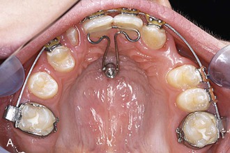
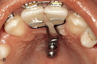
Figure 18-28 A, T-bow front anchorage mechanics on one mini-implant. B, T-bow front anchorage mechanics on two mini-implants. After insertion of the mini-implants, a Beneplate with a 1.1-mm stainless steel wire in place is bent and adapted. Depending on the insertion axis and the position of the mini-implants, the Beneplate body may need to be adapted as well. After fixation of the Beneplate on top of the mini-implants by tiny fixing screws, the wire is bonded to the lingual surfaces of the central incisors.
Clinical Example Using the T-Bow
The patient was a 14-year-old female with missing upper lateral incisors and second molars. The treatment plan was mesialization in the upper arch without anchorage loss of the incisors by using a T-bow. After leveling, one Benefit mini-implant was inserted in the anterior palate (Fig. 18-29, A). An abutment with a 1.1-mm stainless steel wire in place (see Fig. 18-2, B) was adapted to fit between the mini-implant and the incisors (see Fig. 18-28, A). Following bonding of the T-bow an elastic chain was used to apply mesialization forces to the lateral dentition. After 17 months the upper dentition was mesialized (Fig. 18-29, C, D). The treatment result showed a well-preserved overjet and a proper occlusion. However, it seems recommendable to use two mini-implants (see Fig. 18-28, B) to achieve a high anchorage quality.
Clinical Application of the Mesialslider
After insertion of two Benefit mini-implants, bands with lingual sheaths are fixed to the upper molars. Subsequently, two Benetubes and a Beneplate with a 1.1-mm stainless steel wire in place are adapted to the curvature of the palate. To avoid irritation of the soft tissues, the Benetubes must be bent in most cases. Depending on the axis and the location of the two mini-implants, the Beneplate body also must be bent. The mesialization force is delivered by two Ni-Ti closing springs (200 g) that are attached to the activation locks. The Beneplate is fixed by two fixing screws using a screwdriver or the contra angle and the handpiece, which is more comfortable. Finally, the Mesialslider is activated by pushing the activation locks mesially (Fig. 18-30). In cases with missing second premolars or first molars, the Mesialslider can be inserted without putting brackets on the other teeth. Similar to the Beneslider, the Mesialslider can be installed without the need for laboratory work in terms of welding or soldering. In other words, the Mesialslider device can be applied directly in the oral cavity without an impression but can also be fabricated indirectly to save chair time.
Stay updated, free dental videos. Join our Telegram channel

VIDEdental - Online dental courses


