14
Retention Appliances
Introduction
This chapter presents basic concepts and procedures essential to the making of retainers delivered at the end of active orthodontic treatment. Clinicians who ask a laboratory service to make an effective retainer must know how to properly design it and be able to judge the quality of the product, fit it into the mouth, and adjust it.
The purpose of retainers is to hold the teeth in their new positions until the soft and bony tissues have stabilized. After full edgewise appliance treatment, retainers are usually worn full-time for 6 months and at nights for an indefinite period of time. In mixed-dentition patients, retainers are worn for 1 year or until the beginning of the permanent dentition. The lower lingual and palatal holding arches are worn until the permanent canines and premolars have erupted.
Fixed Retainers and Tooth Positioners
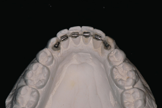
Fixed retainers will be discussed in this chapter only in this brief introduction. Fixed bonded lingual retainers between upper central incisors (1 × 1) prevent the reopening of a diastema in the maxillary arch. Upper lingual fixed retainers require adequate overjet and smaller than normal overbite for successful placement. The patient must not bite on hard food with the anterior teeth because this can dislodge the retainer. Fixed bonded lingual retainers between the lower canines (3 × 3) help maintain intercanine width and canine positions and support alignment of the lower incisors. These fixed retainers have a limited life, usually about 10 years.
These fixed retainers collect food debris and make using floss between the teeth a chore. The lower fixed retainer will collect dental calculus, requiring periodic cleaning by a dental hygienist. The fixed retainers may come loose. In some situations, the retainer can be carefully rebonded to the tooth or teeth. In many cases, the best choice is to remove the remaining bonds and replace the fixed retainer with a Hawley or other removable retainer. Figure 14.1 shows a prescription for maxillary and mandibular fixed retainers. Figures 14.2 through 14.6 show different sizes and shapes of fixed bonded retainers.
Figure 14.1. Bonded retainers prescription.
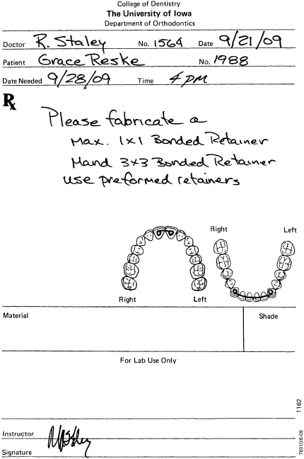
Figure 14.2. Bonded maxillary 1 × 1 retainer.
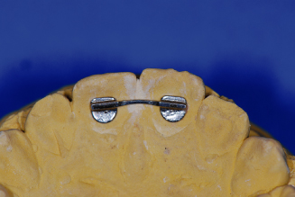
Figure 14.3. Bonded mandibular 3 × 3 retainer.
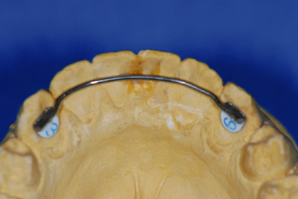
Figure 14.4. Bonded retainer kit (TP Orthodontics, Inc.).
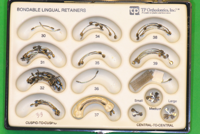
Figure 14.5. Bonded 0.030-inch round, stainless steel wire, canine to canine.
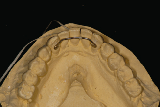
Figure 14.6. Bonded Krause bonded 3 × 3 retainer.
Tooth positioners are used by orthodontists to improve the fit and occlusion of the teeth immediately after removal of the fixed appliance (Kesling 1946). The patient is usually asked to wear the tooth positioner for as many hours a day as possible for about 1 month. The teeth are somewhat mobile after the fixed appliance is removed and remain so for a few weeks. It is during this time that a cooperative patient can improve the occlusion of the teeth by wearing a tooth positioner. After wearing the tooth positioner, Hawley retainers are made for maintenance of the occlusion. Figure 14.7 is a prescription form for requesting a laboratory to make a tooth positioner. Figures 14.8 through 14.10 are views of the tooth positioner and the casts with the teeth set in ideal occlusion used to make the tooth positioner.
Figure 14.7. Prescription for a tooth positioner.
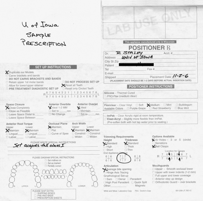
Figure 14.8. Clear tooth positioner, with air holes.
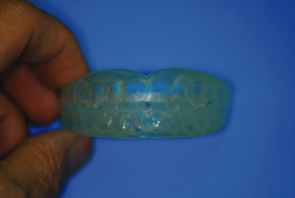
Figure 14.9. Tooth positioner cast setup.
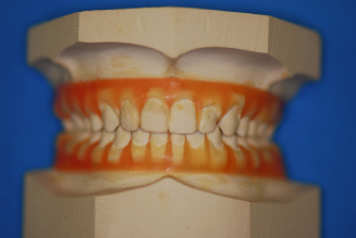
Figure 14.10. White rubber tooth positioner on casts.
Invisible Retainers
Invisible thermoplastic retainers have been in use since the 1970s and are made with clear thermo formed materials that range from 0.5-mm (0.020-inch) to 1.5-mm (0.060-inch) thickness. They should be formed and trimmed so that they maintain arch width and tooth rotations, are strong and not brittle, and are comfortable for the patient to wear 24 hours per day.
The invisible retainer has become more a part of permanent retention because of low cost, ease of fabrication, and high degree of stabilization of the dentition. However, for long-term use, wear and breakage are disadvantages compared to the Hawley retainer designs.
A laboratory prescription is shown for invisible retainer fabrication (Fig. 14.11). The fabrication of maxillary and mandibular invisible retainers is shown in Figures 14.12 through 14.35. Working casts are prepared for construction of the removable appliances by carefully removing positive defects and filling negative defects with stone or light curing resin. In the mandibular arch, remove the tongue to expose the lingual areas and allow access to create a lingual flange in the appliance. Also look for undesirable undercuts around all teeth and block-out as necessary, especially with patients with periodontal problems or missing teeth.
Figure 14.11. Prescription for invisible retainers.
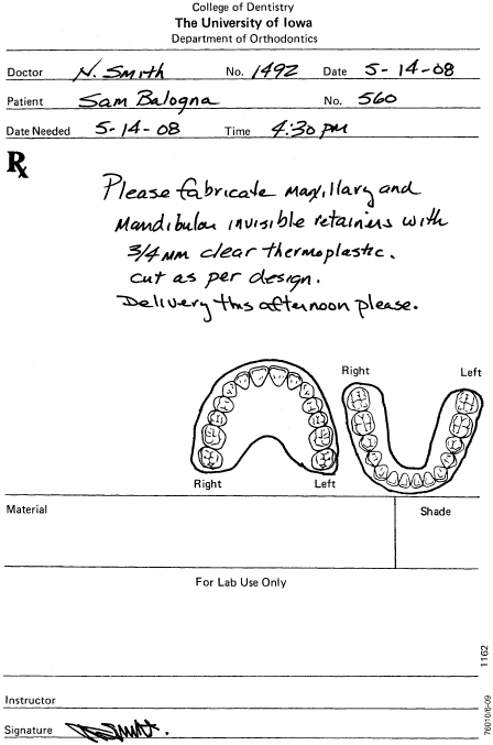
Figure 14.12. Invisible retainers, set.
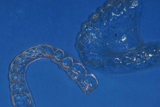
Figure 14.13. Remove positive bubbles.
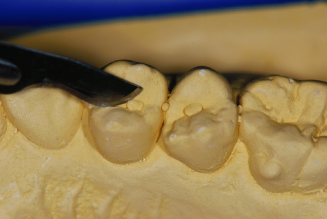
Figure 14.14. Fill voids with light-cure resin or stone.
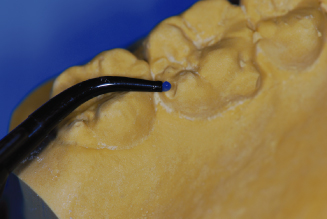
Figure 14.15. Biostar thermo forming machine.
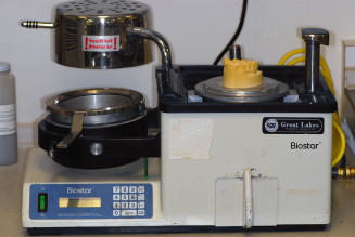
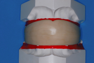
Figure 14.16. Maxillary cast set in lead pellets, with 5 mm between gingival margins and lead pellets.
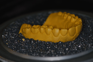
Figure 14.17. Maxillary cast in position; separator has been applied.
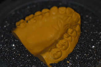
Figure 14.18. Biostar chamber closed with air pressure applied for 2 minutes.
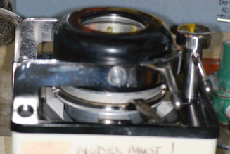
Figure 14.19. View inside chamber.
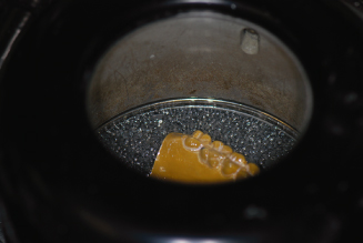
Figure 14.20. The ¾-inch or 1-mm material has been formed for invisible retainer.
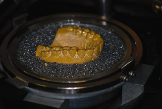
Figure 14.21. Mandibular cast positioned with lingual length of 6 mm accounted for.
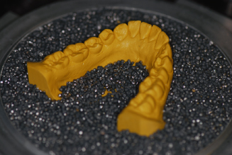
Figure 14.22. Material formed for mandibular invisible retainer.
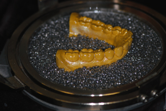
Figure 14.23. Carbide bur and safe-side disc used for removal of retainers from casts.
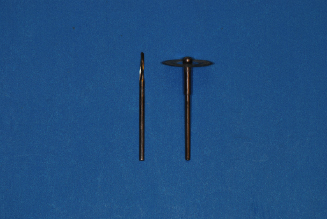
Figure 14.24. Safe-side disc used to rough cut retainer.
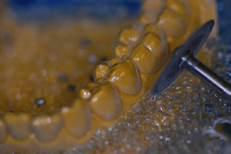
Figure 14.25. Carefully pry retainer from cast with a wax spatula.
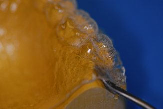
Figure 14.26. Trim to desired length with crown shears.
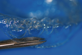
Figure 14.27. Ruby carver stone and sandpaper mandrel with 150 grit sandpaper.
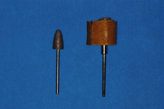
Figure 14.28. Ruby carver smoothing and trimming to length.
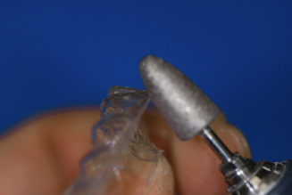
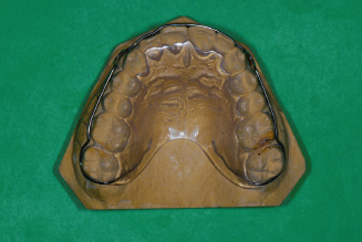
Figure 14.29. Maxillary invisible retainer with full palatal coverage.
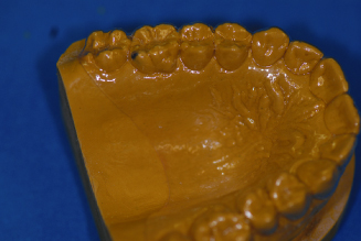
Figure 14.30. Facial length trimmed just below gingival margins.
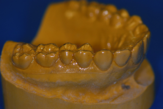
Figure 14.31. Mandibular posterior lingual length trimmed 5 to 6 mm below gingival margins.
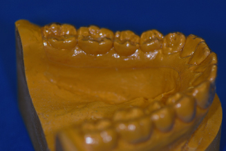
Figure 14.32. Smooth edges of both retainers with sandpaper.
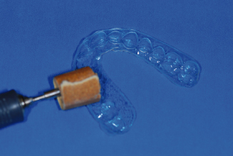
Figure 14.33. Mandibular anterior lingual 3 mm below gingival margins.
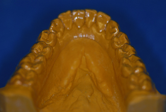
Figure 14.34. If undesirable undercuts exist, shorten facial to middle of teeth.
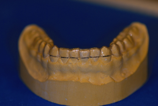
Figure 14.35. Finished set of invisible retainers.

Since we attempt to use the same casts for the Hawley retainer construction, we prefer to have strong casts with flat, solid bases that are approximately 12 mm thick at the thinnest point. Apply silicone spray or liquid separating foil to the casts. Position the cast on the Biostar in the lead pellets cup so that the area 5 mm below the gingival margin of the cast is at the same height as the cup rim. Adapt the pellets from the cast to the cup’s rim.
We prefer a full palatal coverage for invisible retainers, especially when maxillary expansion was part of the orthodontic treatment. Place a sheet of 0.75-mm (0.30-inch) clear retainer material on the chamber and secure it with the frame clamp. Heat the material according to the manufacturers directions for heating and cooling times. After forming the material, cool for 2 minutes under pressure to avoid backpressure distortion. Remove the maxillary cast with the material still in place. Set aside. Now place the mandibular cast into the pellets, again so that the area 5 mm below the gingival margin is at the same height as the cup rim. Place pellets in the lingual area only to a height that will leave 6 to 8 mm below the gingival margin exposed. Adapt pellets to the cup’s rim. Form the material for the mandibular cast. Cool for 2 minutes, and remove the cast and appliance from the machine.
Cut out the material from the casts by using a safe-side lightning disk for thin materials or a carbide bur for thicker materials. Cut across the back of the casts and around the facial surface just above the line where the lead pellets meet the cast, approximately 4 mm from the facial gingival margins. Remove the material from the casts carefully by prying with a wax spatula at the most distal points and in the anterior vestibule to avoid cast breakage. Thin materials may be trimmed with a pair of crown shears. Thicker materials must be trimmed with heavy plate shears or a carbide cutting bur. Reduce the material facially to 2 mm below the gingival margin and form a horseshoe shape in the palate distal to the first molars terminating at the distal embrasure of the last tooth on both sides of the arch on a full coverage appliance. If palatal coverage is not desired, cut the palate of the invisible retainer 6 to 8 mm below the lingual gingival margin. Smooth the trimmed areas with a ruby carver and finish with 150 grit sandpaper on a sandpaper mandrel.
Essix Retainers
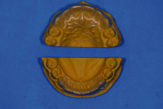
The Essix retainer (Sheridan et al. 1993) is another form of invisible retainer that covers only the anterior section of the dental arches canine to canine. This reduces the appliance bulk and allows posterior teeth to “settle” into full occlusal contact. Both maxillary and mandibular casts can be placed into the thermoplastic forming machine and formed at the same time, thus using only one sheet of 1-mm (0.040-inch) material to fabricate both appliances. Removal, trimming and smoothing are accomplished in the same manner as invisible retainers. Figure 14.36 shows a laboratory prescription for fabrication of Essix retainers. Figures 14.37 through 14.40 illustrate the laboratory fabrication steps for Essix retainers.
Figure 14.36. Prescription for an Essix retainer.
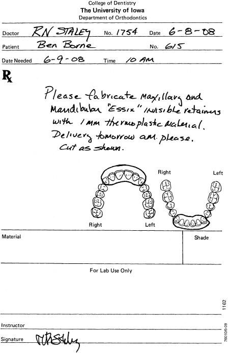
Figure 14.37. Maxillary and mandibular Essix retainers.
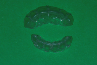
Figure 14.38. Casts ready for thermo-plastic application in Biostar.
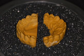
Figure 14.39. Finished Essix retainers trimmed to distal of canines.
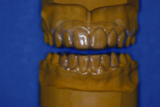
Figure 14.40. Finished Essix retainers. Note: Lingual length.
Basic Retainer Design
The standard “Hawley retainer” is a removable appliance that was developed in the United States in the early 1900s by Dr. C. A. Hawley (1919). Dr. Hawley’s design features a wire to maintain arch shape, wires for retention, and an acrylic body to hold the maxillary and mandibular teeth in place while the patient is wearing the retainer. This design also allows the patient to remove the appliance for eating and cleaning of the teeth and cleaning of the appliance.
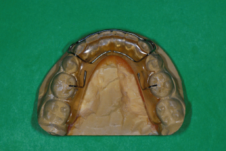
A standard maxillary Hawley retainer consists of a labial bow that spans from the distal of one canine to the distal of the other canine and two clasps on posterior teeth on either side of the arch that are embedded into acrylic on the palatal side (Fig. 14.41). A standard mandibular Hawley retainer consists of a canine-to-canine labial bow and either two clasps or two occlusal rests on posterior teeth on either side of the arch that are embedded into a lingual body of acrylic (Fig. 14.42).
Figure 14.41. Standard maxillary Hawley retainer.
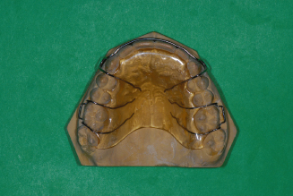
Figure 14.42. Standard mandibular Hawley retainer.
Variations of the Hawley retainer design are modifications to the original design usually requiring that the labial bow be extended and soldered to the clasps (Fig. 14.43). Another modification to the Hawley design is one creating a wraparound design, without clasping, that has the labial bow extending to the most distal posterior teeth before crossing to the lingual side to be embedded into acrylic (Fig. 14.44).
Figure 14.43. Modified Hawley labial bow soldered to Adams clasps.
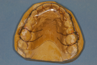
Figure 14.44. Modified Hawley wraparound retainer.
Clasping for removable Hawley appliances can be in the form of simple arrow, ball, buccal tube, or c-clasps or more complicated forms such as the Adams or ReSta clasps that aid in maintaining stability of the removable retainer and thus the stability and position of the teeth.
Wire-Bending Skills
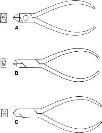
Before the clinician/technician can start to fabricate or adjust removable retainers, some basic wire-bending skills must be learned. Wire-bending exercises are designed to teach techniques necessary to produce and make adjustments to quality orthodontic appliances. Tools used for bending and cutting wires in the laboratory consist of at least three pliers, a cutter, and a wire turret. Figure 14.45A shows bird beak pliers. Figure 14.45B shows a Hawley loop pliers. Figure 14.45C shows a three-prong pliers.
Figure 14.45. (A) Bird beak pliers. (B) Hawley loop pliers. (C) Three-prong pliers.
The bird beak No. 134 or 139 pliers (Fig. 14.46) are designed to make sharp, rounded bends in a wire. The pliers consist of a flat, triangular pad that opposes a conical beak. The wire is held between the beaks and finger pressure is applied to form bends around the conical beak. Sharp bends are made close to the tip of the cone, whereas rounded bends are formed toward the base of the cone. The conical beak design causes less stress on the wire compared to bending the wire over square edge pliers.
Figure 14.46. Bird beak pliers. Finger or thumb bends wire around round beak.

The second pliers used for rounded bends are Hawley loop bending pliers (Fig. 14.47). These pliers feature a small round tip, a step to a larger round section, and a step to a convex contouring section with square sides on one beak while the opposing beak has serrations and a small square section at the tip, a step to a larger square section, and a step to a concave section. The tip makes small helices, the middle section can make perfect adjustment loops or helices, and the third section can gently contour and form a labial bow.
Figure 14.47. Hawley loop pliers. Finger or thumb bends wire around larger round beak for perfect adjustment loops.
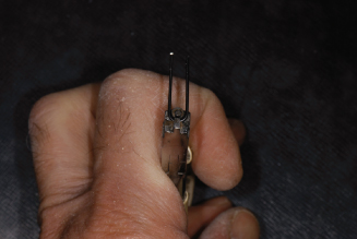
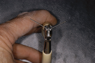
The three-prong pliers (Fig. 14.48) are used with heavy 0.026- to 0.036-inch wire. Bends are formed by squeezing the pliers. With the wire placed at the reference mark on the wire, the two prongs located on one side of the pliers push the wire around the opposing side single prong, creating a “V” bend. Three common uses of the three-prong pliers are to adapt the arch wire to tooth anatomy, to bend acrylic retaining zigzags, and to make wire adjustments. For bends greater than 45 degrees, do not use three-prong pliers as gouging of the wire may occur.
Figure 14.48. Three-prong pliers. Single beak pushes wire between the double beaks squeezing pliers.
Many other pliers are available that produce different sizes and shapes of bends for clinical use, but the three mentioned here will be adequate for most laboratory wire bending.
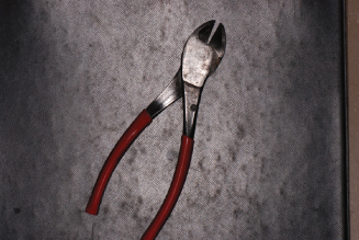
A high-quality hard diagonal wire cutter (Fig. 14.49) is essential for cutting wires from 0.012 to 0.040 inch. In the operatory, ligature tie cutters are used for 0.009- to 0.011-inch soft wire ties and end cutters are used for clipping all sizes of hard arch wire from 0.012 to 0.028 inch.
Figure 14.49. Hard wire cutter.
The wire turret (Fig. 14.50) may be used to bend wires with perfect parabolic shape for labial bows and lingual arches without introducing stress inducing bends or nicks from pliers.
Figure 14.50. Easy parabolic wire bends made around a wire turret, which puts less stress into wire.

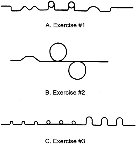
Figure 14.51A-C show three exercises for wire bending practice. For exercise 1, use the No. 134 bird beak pliers and a 7-inch piece of 0.030-inch round, stainless steel wire on the pattern. For exercise 2, use the three-prong pliers and a 7-inch piece of 0.030-inch round, stainless steel wire on the pattern. For exercise 3, use the No. 134 bird beak and/or the Hawley loop bending pliers and a 7-inch piece of 0.026-inch round, stainless steel wire on the pattern.
Figure 14.51. (A) Exercise No. 1: Bend a 7-inch length of 0.030-inch round wire with bird beak pliers to match form. (B) Exercise No. 2: Bend a 7-inch length of 0.030-inch round wire with three-prong pliers to match form. (C) Exercise No. 3: Bend a 7-inch length of 0.026-inch round wire with bird beak and/or Hawley loop pliers to match form.
After you have successfully formed each of the exercise patterns and become comfortable with the pliers, you are ready to adapt labial bows, clasps and springs for retainer fabrication.
Maxillary Labial Bow Bending
The Hawley labial bow is a basic retainer design that can be used if no occlusal interferences exist at the distal occlusal margin of the canines. The labial bow aids in appliance retention and maintains the alignment of anterior teeth during this final phase of treatment. Many general dentists’ request that the labial bow be formed into an average arch form. If done so, the bow will not always touch all the anterior teeth in a manner that would be necessary to maintain the tooth positions.
The orthodontist has carefully achieved ideal tooth positions with the fixed appliance and desires retainers that will maintain those positions. The use of tooth positioners to improve final positioning and invisible retainers to hold exact position suggests that the labial bow must contact all of the anterior teeth intimately to prevent undesirable rotation recurrence.
Newcomers are advised to draw the desired position of the wire on the cast prior to bending. A 7-inch length of 0.030-inch round stainless steel wire is formed around a wire turret to produce a perfect parabolic curve relative to the patient’s anterior tooth alignment. Place the wire on the cast and mark the midline on the wire with a permanent marker (fine point Sharpie). The wire should approximate the arch shape from canine to canine. Open or close the parabolic curve to match the arch shape. Carefully bend to maximum contact from mesial line angle to distal line angle on the centrals and laterals, and from the mesial line angle to the center of the canines in order to maintain the exact positions of these teeth. Remember to always check bends by positioning the wire center mark in exactly the same place at the midline between the centrals. Also lay the wire flat on the tabletop to ensure you are bending each bend on the same horizontal plane. At the distal line angle of the center mark, bend the wire toward the mesial line angle of the lateral. Check the bend and increase or offset if desired. Then bend the wire to fit the lateral from mesial line angle to distal line angle. Check bends making sure wire maintains contact with both the central and lateral before proceeding. Next mark the wire at the distal line angle of the lateral and mark between the lateral and canine. Bend the wire toward the mesial line angle of the canine and bend a canine offset to achieve wire contact from the mesial line angle of the canine to the middle of the canine. Check bends again. The central, lateral, and canine should all have contacts and the wire should also lay flat on the tabletop. Now work from the midline to the opposite canine in the same manner. When completed, the wire should remain in intimate contact with the centrals, laterals, and the mesial half of the canines.
Do not proceed until you have passive contact with all six anterior teeth. Upon completion of the labial bow bending from canine to canine, the wire must be passive, lie on the drawn horizontal plane, and contact each central, lateral, and canine properly to maintain the ideally positioned teeth in their finished position.
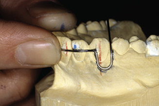
Once satisfied, continue by marking the wire 1 mm mesial to the midpoint of the canine and make a 90-degree bend toward the gingiva and slightly out away from the tissue. Adjustment loops of 5 to 7 mm in width and length are located near the midpoints of the canines and terminate in the acrylic in the palate mesial to the first premolars. Use bird beak pliers or Hawley loop bending pliers to bend perfectly shaped adjustment loops in your labial bow wire. Adjust the loop so the loop is parallel to, but not touching, the tissue. Angle the distal side of the loop toward the occlusal embrasure and between the canine and first premolar. Bend the wire tightly through occlusal embrasure and downward toward the palatal tissue.
All wires crossing occlusal embrasures into lingual acrylic must be closely adapted to eliminate possible interference with opposing teeth. Maintain 0.5-mm space between the wire and the palatal tissue and make retention bends at the end of the wire. The wire should be 10 to 15 mm long from the point at which it crosses the occlusal embrasure to the end. Check the wire again to ensure each tooth is still in contact and the wire is on the drawn horizontal plane. If it is not ideal, adjust it until it is. Then proceed to bend the opposite adjustment loop. Mark the wire 1mm mesial to the middle of the opposite canine and bend a 90-degree bend toward the gingival tissue. Make the adjustment loop again 5 to 7 mm wide and keep the top of the loop slightly off the tissue. Bend the distal of the loop toward the occlusal embrasure and bend it tightly through the occlusal embrasure. Bend the wire 0.5 mm above the tissue on the palatal side. Cut to 10 to 15 mm in length from the occlusal contact and make retention bends in the end of the wire.
Check the wire for fit again. The wire must be passive, lie on the drawn horizontal plane, and contact each central, lateral, and canine properly in order to be able to maintain the ideally positioned teeth in their finished position. Figure 14.52 shows a prescription for a maxillary Hawley retainer with labial bow and Adams clasps. Figure 14.53 shows a completed labial bow on a maxillary cast. Figures 14.54 through 14.109 illustrate the step-by-step bending of the maxillary labial bow. Figure 14.110 shows a completed maxillary Hawley retainer with labial bow and Adams clasps.
Figure 14.52. Prescription for a maxillary Hawley retainer with Adams clasps.
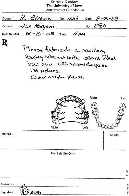
Figure 14.53. Maxillary labial bow.
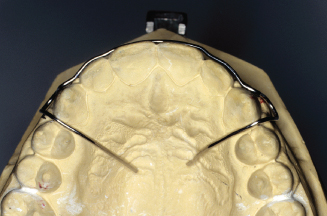
Figure 14.54. Mark the middle of centrals to position wire height on cast.
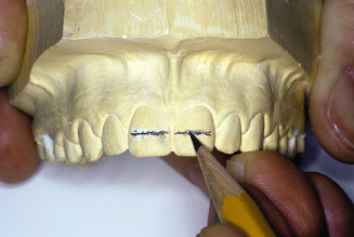
Figure 14.55. Continue line to laterals and canines on the horizontal plane.
Figure 14.56. Mark long axis of canines. Draw 5- to 6-mm adjustment loops onto cast.
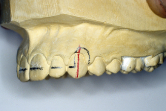
Figure 14.57. Bend a 7-inch length of 0.030-inch round wire around wire turret.
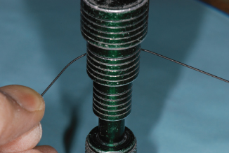
Figure 14.58. Check parabolic curve, open or close curve for shape across centrals. Mark wire at midline with a Sharpie pen for later wire checks.
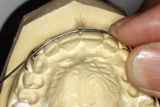
Figure 14.59. The goal is to contact each central and lateral, line angle to line angle.
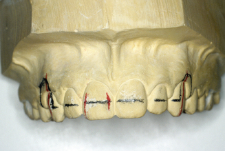
Figure 14.60. Check and mark wire for a lateral inset bend. Mark the wire directly between the central and lateral.
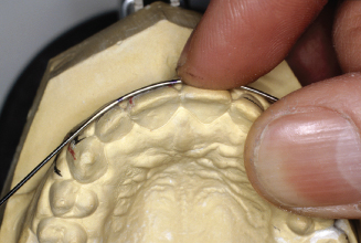
Figure 14.61. Always try to bend wire on the horizontal plane. Position wire perpendicular to the pliers.
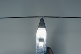
Figure 14.62. Place wire into pliers on the mark between the central and lateral.
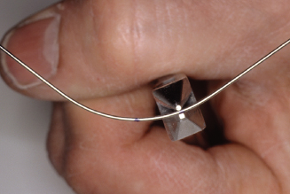
Figure 14.63. With finger, pull in on central side of wire.
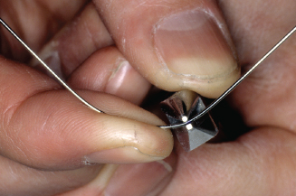
Figure 14.64. With thumb, push out on lateral side of wire.
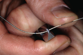
Figure 14.65. Check central and mesial contact on lateral.
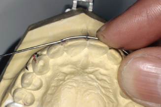
Figure 14.66. Mark last point of wire contact on lateral.
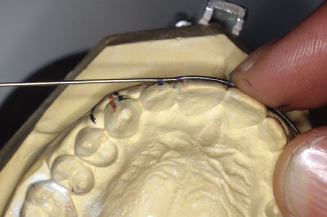
Figure 14.67. With mark just outside pliers, bend wire toward the lingual.
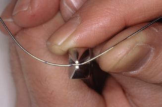
Figure 14.68. Check contacts on central and lateral.
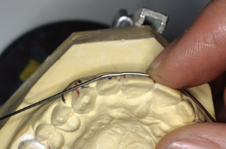
Figure 14.69. Mark last point of contact on lateral.
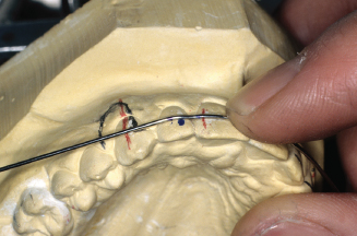
Figure 14.70. Also mark for canine offset between lateral and canine.
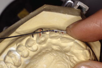
Figure 14.71. With the wire in pliers, place offset mark just outside of beak and bend wire facially.
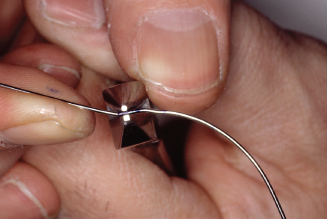
Figure 14.72. Check offset bend and wire contacts to lateral and central. Adjust where necessary.
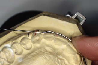
Figure 14.73. Check wire often to be sure wire is being bent parallel to horizontal plane.
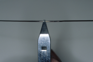
Figure 14.74. With the wire mark placed at midline check contacts on patients right central, lateral and canine, and left central. Mark between left central and lateral for the lateral inset bend.
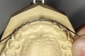
Figure 14.75. Place lateral bend mark between pliers beaks and bend wire to lingual on the central side.
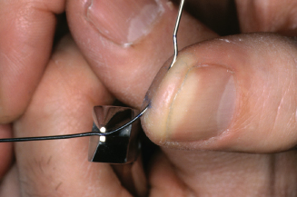
Figure 14.76. Also bend facially on lateral side of pliers.
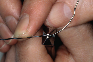
Figure 14.77. Check fit to left central and mesial of lateral. Mark last point of contact on lateral.
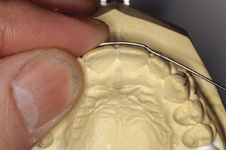
Figure 14.78. Bend around to distalline angle of lateral to make contact with canine. Mark canine offset bend between lateral and canine. Bend canine offset.
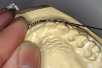
Figure 14.79. Check fit from midline to mesial of left canine.
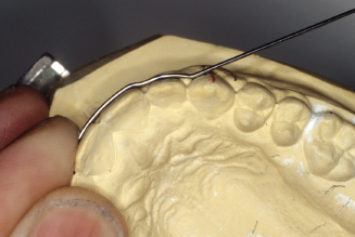
Figure 14.80. Check wire against line on casts’ horizontal plane.
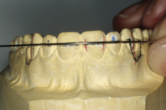
Figure 14.81. Adjustment loop 90-degree bends should be 1mm mesial to middle of canines.
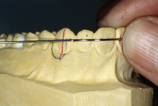
Figure 14.82. Mark wire for 90-degree adjustment loop bend.
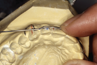
Figure 14.83. With mark just outside pliers beaks, make bend.
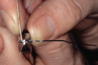
Figure 14.84. Check bend; it should be parallel to long axis of canine.
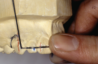
Figure 14.85. Adjustment loop bends must also slant out away from tissue contact above canine.
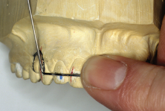
Figure 14.86. Place wire deep into pliers to bend around the middle of the conical beak to make a 5- to 7-mm adjustment loop.
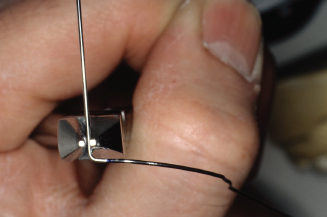
Figure 14.87. Also check the angle of adjustment loop, bend parallel to canine.
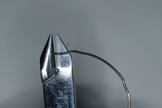
Figure 14.88. Make the adjustment loop bend.
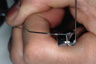
Figure 14.89. Check and adjust distal arm of loop to align with canine and premolar embrasure.
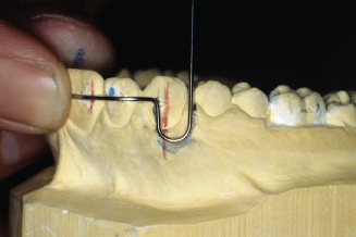
Figure 14.90. Check from occlusal; loop needs to be bent parallel to canine.
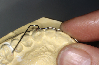
Figure 14.91. Place mesial side of adjustment loop into pliers, and with thumb, bend distal side of loop toward lingual. If wire was contacting the cast on the distal side, the bend would have to be made in the opposite direction.
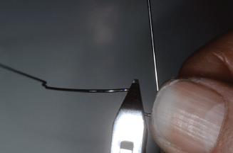
Figure 14.92. Check wire to cast again. Loop must not contact tissue and wire must still contact canine, lateral, and central.
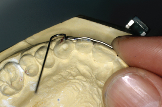
Figure 14.93. Mark where wire needs to bend toward occlusal embrasure.
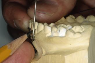
Figure 14.94. Check bend from distal buccal view.
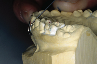
Figure 14.95. Check bend from facial view. Distal arm must align between canine and premolar.
Stay updated, free dental videos. Join our Telegram channel
VIDEdental - Online dental courses


